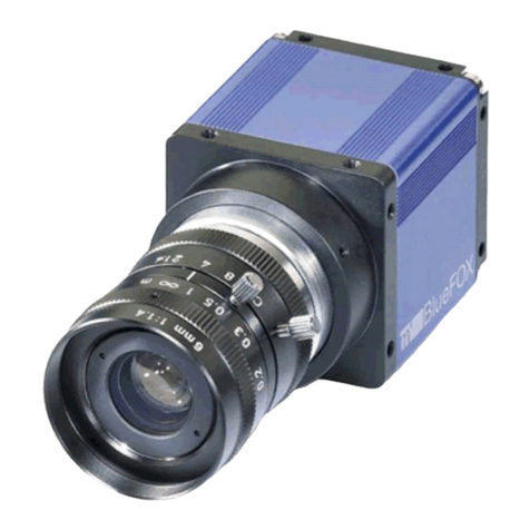
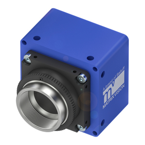
Matrix Vision BVS CA - GX0 XAS2 Series User manual

deutsch
MATRIX VISION GmbH Talstraße 9 71570 Oppenweiler, Deutschland
Einleitung
Diese Kurzanleitung behandelt nur die Bedienung der BVS
Industrial Camera bis zum Öffnen der Konfigurationsober-
fläche BVS Cockpit. Ausführliche Bedienungsanleitungen
finden Sie auf www.balluff.com
Hinweis
Zur sicheren Bedienung müssen die Betriebsanlei-
tung auf der BVS Industrial Camera und die dort
enthaltenen Warn- und Sicherheitshinweise unbe-
dingt gelesen und beachtet werden.
Anschlüsse
1
2
1LAN
2Power-I/O
Anschluss Funktion
Power-I/O Spannungsversorgung der BVS Industrial
Camera inklusive vier digitalen Ein- und
vier digitalen Ausgängen.
LAN Bindet die Kamera in ein lokales Netzwerk
ein.
Pinbelegung
LAN (Gigabit Ethernet)
Buchse M12, 8-polig, X-kodiert
Pin Signal Funktion
1 BI_DA + Bidirectional data, Pair A +
2 BI_DA - Bidirectional data, Pair A -
3 BI_DB + Bidirectional data, Pair B +
4 BI_DB - Bidirectional data, Pair B -
5 BI_DD + Bidirectional data, Pair D +
6 BI_DD - Bidirectional data, Pair D -
7 BI_DC – Bidirectional data, Pair C -
8 BI_DC + Bidirectional data, Pair C +
Pinbelegung (Fortsetzung)
Power-I/O
Stecker M12, 12-polig
Pin Signal Funktion
1 PWR_IN+ 11 V bis 25 V Versorgung
2 PWR_IN-/GND Masse
3 DigOut3 Ausgang
4 Opto DigIn0 Optischer Eingang
5 DigOut2 Ausgang
6 DigOut0 Ausgang
7 Opto GND Masse für Eingänge
8 Opto DigIn2 Optischer Eingang
9 Opto DigIn3 Optischer Eingang
10 +24V_HSD 24V für die Ausgänge
11 Opto DigIn1 Optischer Eingang
12 DigOut1 Ausgang
Hinweis
Die digitalen Eingänge entsprechen der Richtlinie
über Eingänge EN 61131-2, Typ 3. Jeder Ausgang
darf mit maximal 700mA belastet werden. Die Last
oder Versorgung muss entsprechend begrenzt
werden.
Mit dem CE-Zeichen bestätigen wir, dass
unsere Produkte den Anforderungen der
aktuellen EU-Richtlinie entsprechen.
BVS CA - GX0 - _ _ _ _ _ _ - _ _ _ _ _ _ - XAS2
BVS INDUSTRIAL CAMERA
Kurzanleitung
deutsch
MATRIX VISION GmbH Talstraße 9 71570 Oppenweiler, Deutschland
Nr. 947135-726 DE ∙ 01.130179 ∙ H20; Änderungen vorbehalten. Ersetzt D20.
Inbetriebnahme
Neben der BVS Industrial Camera wird folgendes
benötigt:
– Aktuelle BVS Industrial Camera Treiber
– Power-I/O Kabel
– Netzteil 11 V - 25 V
–LAN-Kabel Gigabit Ethernet
Anforderungen: min. Kategorie 5e nach EIA/TIA-568
– PC mit Webbrowser
Google Chrome ab Version 32.0, Mozilla Firefox ab
Version 24.0, Microsoft Internet Explorer ab Version 11,
Microsoft Edge ab Version 40.
Hinweis
JavaScript muss im Webbrowser aktiviert sein.
Schritt 1: Treiber installieren
►Aktuelle Treiber (Windows) erhalten Sie auf www.balluff.
com.
Schritt 2: Netzwerkverbindung herstellen
►Verbinden Sie die BVS Industrial Camera über die
Buchse LAN.
Üblicherweise ist die Netzwerkkonfiguration Ihres Rechners
auf IP-Adresse automatisch beziehen eingestellt. Bei der
Firewall-Einstellung sollte der Port 80 freigegeben sein.
Folgende Netzwerkstrukturen sind möglich:
– Direkte Verbindung über ein LAN-Kabel: IP-Adressen
werden automatisch eingestellt.
– Verbindung im gleichen Subnet eines lokalen Netz-
werks mit DHCP: IP-Adressen werden automatisch
eingestellt.
Schritt 3: BVS Industrial Camera einschalten
►Verbinden Sie jetzt die Stromversorgung am Anschluss
Power I/O mit dem Netzteil.
Das Starten dauert ca. 30 s.
Hinweis
Die Verbindung kann etwas Zeit in Anspruch neh-
men.
Schritt 4: GigE Vision kompatible Software öffnen
Die Kamera kann beispielsweise über das BVS Cockpit
Release 2.7 oder höher konfiguriert werden. Starten Sie
BVS Cockpit und wählen Sie das Tool "Kamera einrich-
ten" bzw. unter Systemeinstellungen können Sie über den
Menüeintrag "Digitale Ein/Ausgänge" die digitalen Ein-/
Ausgänge einrichten.
BVS CA - GX0 - _ _ _ _ _ _ - _ _ _ _ _ _ - XAS2
BVS INDUSTRIAL CAMERA

english
MATRIX VISION GmbH Talstrasse 9 71570 Oppenweiler, Germany
Introduction
This condensed guide applies only to the operation of the
BVS Industrial Camera up to opening the BVS Cockpit
configuration interface. Detailed operating instructions are
located on www.balluff.com
Note
Safe operation requires that the operating inst-
ructions for the BVS Industrial Camera and the
warning and safety instructions it contains must be
read and observed.
Connections
1
2
1LAN
2Power
I/O
Connection Function
Power I/O Voltage supply of the BVS Industrial Ca-
mera including four digital inputs and four
digital outputs.
LAN Integrates the BVS Camera in a local
network.
Pin assigment
LAN (Gigabit Ethernet)
Socket M12, 8-pin, X-coded
Pin Signal Function
1 BI_DA + Bidirectional data, Pair A +
2 BI_DA - Bidirectional data, Pair A -
3 BI_DB + Bidirectional data, Pair B +
4 BI_DB - Bidirectional data, Pair B -
5 BI_DD + Bidirectional data, Pair D +
6 BI_DD - Bidirectional data, Pair D -
7 BI_DC – Bidirectional data, Pair C -
8 BI_DC + Bidirectional data, Pair C +
Pin assigment (continued)
Power-I/O
Plug M12, 12-pin
Pi Signal Function
1 PWR_IN+ 11 V .. 25 V power supply
2 PWR_IN-/GND Ground
3 DigOut3 Output
4 Opto DigIn0 Optocoupler Input
5 DigOut2 Output
6 DigOut0 Output
7 Opto GND Ground for Optocoupler
8 Opto DigIn2 Optocoupler Input
9 Opto DigIn3 Optocoupler Input
10 +24V_HSD 24V for the outputs
11 Opto DigIn1 Optocoupler Input
12 DigOut1 Output
Note
The digital inputs correspond to the guideline con-
cerning inputs, EN 61131-2, Type 3. The maximum
load on any outputs is 700mA. The load or supply
must be limited accordingly.
The CE symbol confirms that our products
comply with the requirements of the current
EU directive.
BVS CA - GX0 - _ _ _ _ _ _ - _ _ _ _ _ _ - XAS2
BVS INDUSTRIAL CAMERA
Condensed Guide

english
MATRIX VISION GmbH Talstrasse 9 71570 Oppenweiler, Germany
No. 947135-726 EN ∙ 01.130179 ∙ H20; Subject to modification. Replaces D20.
Startup
Besides the BVS Industrial Camera the following is
required:
– Latest BVS Industrial Camera driver
– Power I/O cable
– Power supply 11 V - 25 V
– LAN cable Gigabit Ethernet
Requirements: at least category 5e acc. to EIA/TIA-568
– PC with web browser
Google Chrome version 32.0, Mozilla Firefox version
24.0, Microsoft Internet Explorer version 11 and above,
Microsoft Edge version 40 and above.
Note
JavaScript must be enabled in the web browser.
Step 1: Installing driver
►Download the latest driver (Windows) from www.balluff.
com.
Step 2: Establishing a network connection
►Connect the BVS Industrial Camera via the LAN port.
In general, the network configuration of your PC is set to
Obtain IP address automatically. For the firewall setting,
port 80 should be enabled.
The following network structures are possible:
– Direct connection via LAN cable: IP addresses are set
automatically.
– Connection in the same subnet of a local network with
DHCP: IP addresses are set automatically.
Step 3: Switching on the BVS Industrial Camera
►Now connect the power supply at the Power I/O with
the power supply.
The start up will take approx. 30 s.
Note
The connection may take some time.
Step 4: Opening a GigE Vision compliant software
The camera can be configured, for example, via the BVS
Cockpit Release 2.7 or higher. Start BVS Cockpit and
select the "Set up camera" tool or choose the "Digital In/
Outputs" menu item in the system settings to set the digital
inputs and outputs.
BVS CA - GX0 - _ _ _ _ _ _ - _ _ _ _ _ _ - XAS2
BVS INDUSTRIAL CAMERA
Table of contents
Languages:
Other Matrix Vision Digital Camera manuals

Matrix Vision
Matrix Vision mvBlueCOGAR-P Series Operating and installation instructions

Matrix Vision
Matrix Vision mvBlueCOUGAR-X User manual

Matrix Vision
Matrix Vision mvBlueFOX3 User manual

Matrix Vision
Matrix Vision mvBlueFOX User manual

Matrix Vision
Matrix Vision mvBlueCOGAR-P Series Operating and installation instructions