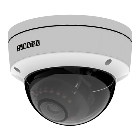
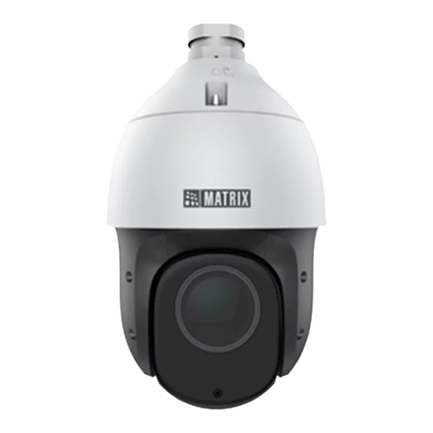
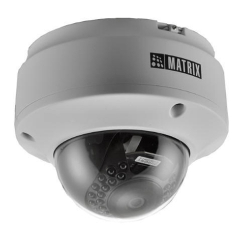
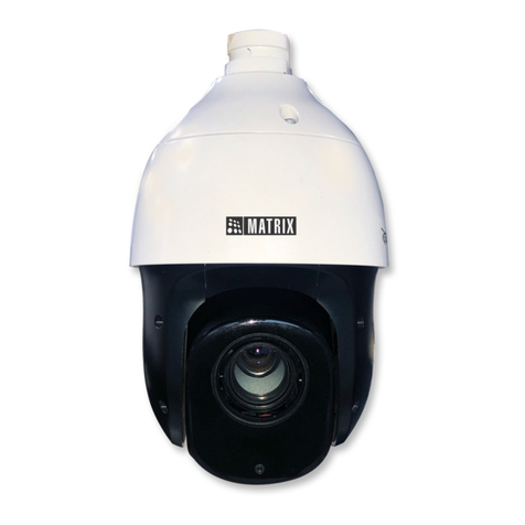
Matrix SATATYA PZCR20ML33CWP User guide

SATATYA PZCR20ML33CWP
System Manual

2
Documentation Disclaimer
Matrix Comsec reserves the right to make changes in the design or components of the product as
engineering and manufacturing may warrant. Specifications are subject to change without notice.
This is a general documentation for all variants of the product. The product may not support all the
features and facilities described in the documentation.
Information in this documentation may change from time to time. Matrix Comsec reserves the right
to revise information in this publication for any reason without prior notice. Matrix Comsec makes no
warranties with respect to this documentation and disclaims any implied warranties. While every
precaution has been taken in the preparation of this system manual, Matrix Comsec assumes no
responsibility for errors or omissions. Neither is any liability assumed for damages resulting from the
use of the information contained herein.
Neither Matrix Comsec nor its affiliates shall be liable to the buyer of this product or third parties for
damages, losses, costs or expenses incurred by the buyer or third parties as a result of: accident,
misuse or abuse of this product or unauthorized modifications, repairs or alterations to this product
or failure to strictly comply with Matrix Comsec operating and maintenance instructions.
Warranty
For product registration and warranty related details visit us at:
http://www.matrixcomsec.com/product-registration-form.html
Copyright
All rights reserved. No part of this system manual may be copied or reproduced in any form or by
any means without the prior written consent of Matrix Comsec.
Release date: August 27, 2021 4:29 PM

3
Preface
Thanks for your kind of using our network dome camera products. This IP
monitoring product is a dome camera, developed specially for monitoring
network videos, which adopt the high-performance, single SOC chip to form a
media processor integrating audio and video collection, compression and
transmission with standard H.264 and H.265 code algorithms ensuring a
clearer and smoother video transmission. The embedded Web Server allows
users to conveniently achieve real-time monitoring and remote control of the
front-end cameras via IE browser.

4
Statement
This manual may have inaccuracies, inconsistencies in the operation and
function of the product or misprint.
• We will update the information of the manual based on the enhancement
and changes of product functions, which will be shown in the latest version
of the manual without further notice.
• Due to the constant adoption of new technologies, the parameters of the
products are subject to change without further notice.
• This manual provides reference and guidance for customs only, which
doesn’t guarantee a total consistency with the real subject. Please take the
real object as actual application.
• The parts, components and accessories mentioned in the manual don’t
represent the standard configuration of the equipment. Please refer to the
packing list for details.
• All text, forms and figure information in this manual are protected by
relevant laws of the country. Please don’t take it for personal usage without
permission.
Target Audience
This manual is mainly applicable to the following:
• System Planners
• On-site Technical Support and Maintenance Staff
• Administrators in charge of installation, configuration and maintenance
• Users of the product

5
Contents
1. Precautions ................................................................................................................. - 1 -
2. Product overview ........................................................................................................ - 4 -
2.1 Main functions and characteristics ................................................................. - 4 -
2.2 Main application occasions ............................................................................ - 6 -
3. Installation Instructions ................................................................................................. - 7 -
3.1 Preparation for Installation .............................................................................. - 7 -
3.2 Installation methods of dome cameras ........................................................... - 8 -
3.3 Illustrations of dome camera and interface dimensions ................................ - 10 -
3.4 Installation steps(take wall-mounted installation as an example) .................. - 12 -
3.5 Illustration of external wiring ......................................................................... - 13 -
4. Descriptions of functions............................................................................................. - 15 -
4.1 Basic function description ............................................................................. - 15 -
5. WEB client .................................................................................................................. - 17 -
5.1 Operating Environment ................................................................................ - 17 -
5.2 Instructions for embedded Web server ......................................................... - 17 -
5.3 Login Device ................................................................................................ - 17 -
5.4 Audios and videos preview ........................................................................... - 21 -
5.5 Playback ...................................................................................................... - 29 -
5.6 Log ............................................................................................................... - 32 -
5.7 Configuration ................................................................................................ - 33 -
5.8 Audio Video Set ............................................................................................ - 37 -
5.9 Dome Set ..................................................................................................... - 53 -
5.10 Network ...................................................................................................... - 61 -
5.11 Event Schedule .......................................................................................... - 72 -
5.12 Smart surveillance (VCA) ......................................................................... - 78 -
5.13 Storage ..................................................................................................... - 103 -
5.14 System ..................................................................................................... - 107 -
6.Simple Troubleshooting .............................................................................................. - 117 -
7. After-sales Services ................................................................................................... - 119 -
8. Appendix I Lightning Protection and Surge Protection .............................................. - 120 -

- 1 -
1. Precautions
The purpose of this Manual is to ensure that users can operate the products
properly, thus avoiding danger or property damage. Please read this Manual
carefully and keep it properly for future reference before using the products.
As shown below, the precautionary measures are divided into two parts:
“Warning” and “Note”:
Warning: ignoring the warning may result in death or severe injury.
Attention: ignoring the precautions may result in injury or property
damage.
Warning Alert users to prevent
the potential danger of death or
serious injury
Note Alert users to prevent the
potential danger of injury or
property damage
Warning:
1. Input voltage should meet both the SELV (Safety Extra Low Voltage)
2. Contact the distributor for abnormal operation. Do not disassemble or
modify the devices in any way.
3. Moisture must be avoided for indoor devices in case of fire and electric
shock.
4. Install the equipment on the ceiling to ensure that it can withstand at least 4
times the weight of the equipment.
5. Do not look directly at the concentrated laser beam.
6. The camera should be installed by professional personnel in the way
complying with local laws and regulations.
7. The easy-to-use power failure protection device should be installed in
building installation wiring.
8. Don’t disassemble internal parts of the camera privately. No internal part

- 2 -
can be privately repaired by the user. Repair work can only be performed by
maintenance staff authorized by our company and we will not be responsible
for any problem caused by unauthorized modification or maintenance of the
product.
Note:
1. Please check whether the power supply is correct before the camera starts
functioning.
2. Please do not drop the product on the ground or do not strongly knock it.
3. Please don’t directly touch the glass and spherical outer cover in front of
the lens. To clean it, you may wipe the surface with microfiber cleaning cloth,
such as glasses cloth. Don’t wipe it too hard or wipe with water.
4. Don’t focus at strong light (such as light, sunlight, laser, etc.); otherwise,
over-bright or light pulling phenomenon (not the fault of the camera) may
occur and the service life of the image sensor may also be shortened.
5. Avoid putting it at places that are damp, dusty, extremely hot, extremely
cold or with strong electromagnetic radiation.
6. It is strongly recommended to transport the camera with the original
package.
7. Long-term high-speed cruising of the camera may lead to ring sliding and
aging of the synchronous belt, thus affecting the machine’s service life.
8. The bending radius of optical fiber cable should not be less than 20mm.
9. The working bid documents of the laser is -10℃~ +40℃. Beyond this range,
the laser will shut down automatically.
10. For details about functions of the camera, please refer to the Help file at
the right upper corner of the IE browser.
11. The analog video port is for rapid debugging and is not the formal video
output port.
12. The running speed of the dome camera will be adjusted automatically
based on the external environment and slightly decrease in the ultra-low

- 3 -
temperature (-under 20℃).
13. Please use the product under the requirement of working environment.
Parameters Dome camera
Ambient temperature -40℃~+70℃
Ambient humidity <95% (no condensation)
Atmospheric pressure 86~106KPa
Power supply AC 24V/3.0A
Attention: make sure that the outdoor installation of the dome camera meets
the waterproof requirements
14. Illustration of dome camera installation environment
To get rid of the vapor in dome camera cover affecting the video effect and
the life of electrical parts, please assemble the ball cover under the condition
of ventilated and dry environment, and ensure that the screws of the dome
camera are tightened.

- 4 -
2. Product overview
This is a high-definition network high-speed dome camera, which are
embedded digital monitoring product integrating traditional analog camera and
network video server. They adopt embedded Linux operation system and
advanced hardware platform, with high dispatching efficiency, code solidified in
Flash, small volume, Low power consumption, high stability and reliability.
This dome camera adopts the integrated design, synchronous belt drive and
precision stepping motor, which can run accurately and stably; different
installation methods meet the needs of different occasions; with weather-wise
outdoor design, double-layer shell structure, built-in fan and intelligent start;
various monitoring methods, such as scanning, cruising, pattern path, etc., are
flexible to be selected; integrated preset function ensures more powerful
performance.
Special attention: the product function description and support functions in
this manual are based on the full-function dome camera.
2.1 Main functions and characteristics
2.1.1 Basic functions
• Heartbeat function: through the heartbeat mechanism, the management
host can get the real-time operation status of the front-end network dome
camera;
• PTZ control function: the RS485 interface (full-function dome camera) can
support PTZ control and multiple decoder protocols and dome camera
protocols;
• Alarming function: alarm input, alarm output, mobile detection alarm, video

- 5 -
loss / blocking alarm, email alarm, alarm link output;
• Voice intercom: two-way voice intercom, one-way voice acquisition /
broadcast;
• User management: multi user limits management modes. Senior
administrator can create 4 sub-levels of users with different level of user's
rights for high system security;
• The embedded Web Server allows IE browser;
• Provide open SDK development package;
• Compression processing capacity;
• Support 25 frames per second (PAL system) / 30 frames per second (NTSC
system)
• Support H.265 coding (full-function starlight dome camera), support
changing not only code rate but also frame rate. When setting the video Fig.
quality, it can also limit the video Fig. compression code stream;
• Support 2MP;Maximum Resolution - 1920x1080
o Main Stream - PAL: 50fps (1920x1080, 1280x720, 704x576,
640x480); NTSC: 60fps (1920x1080, 1280x720, 704x480, 640x480)
o Sub Stream - PAL: 25fps (704x576, 704x288, 640x360, 352x288);
NTSC:30fps (704x480, 704x240, 640x360, 352x240)
o Third Stream - PAL 25fps (1920x1080, 704x576, 704x288, 352x288);
NTSC: 30fps (1920x1080, 704x480, 70x240, 352x240)
• Excellent intelligent analysis and tracking function (full function dome
camera).
2.1.2 Remote access and transmission functions
• A 10m / 100M adaptive Ethernet port is provided as standard;
• Supports TCP / IP, ICMP, FTP, HTTP, DHCP, DNS, RTSP, PPPOE, NTP,
UPnP, SMTP, IGMP, QoS, IPv4, IPv6, Multicast, RTMP;
• Support ONVIF protocol, P2P,GBT28181,GAT1400
• Parameters, real-time video browsing, and viewing webcam status can be

- 6 -
set through the application or IE browser. Alarm link can be achieved
through network;
• Remote management and maintenance can be achieved through remote
network maintenance / upgrading.
2.2 Main application occasions
It is applicable to all kinds of occasions requiring remote network monitoring,
such as:
• ATM, vault, teller and other monitoring occasions;
• Factory, workshop, warehouse and other monitoring occasions;
• Urban street monitoring, road condition information collection and other
occasions;
• Child-care centers, kindergartens, schools and families where need
monitoring;
• Smart building, smart community and other management systems;
• Airport, railway station, bus station and other occasions with frequent
crowd gathering and distribution;
• Oil field and coal mine remote operation occasions;

- 7 -
3. Installation Instructions
3.1 Preparation for Installation
(1) Basic requirements
Ensure that all electrical work must be conducted in accordance with the latest
electrical regulations, fire regulations and related regulations; check whether
the packaging is damaged, equipment and accessories are complete, and
determine whether the application places and installation methods of PTZ
product meet the requirements; please contact the dealer if necessary, please
use the product according to the requirements of the working environment.
(2) Common installation tools
Prepare the tools actually required according to the actual situations
Fig.3.1 Common installation tools
(3) Check the strength of the construction of installation space and installation
site
Confirm that there is enough space at the installation site to accommodate the
product and its mounting structural part. Confirm that the carrying capacity of
the ceiling, wall and bracket on which the PTZ is installed must be able to
support the total weight of PTZ and its mounting structural part, with a 4 times

- 8 -
of safety factor.
Please keep all packaging materials of network camera
After unpacking the network camera, please keep the original packaging
materials of network camera properly, and pack the network camera product
properly using the packaging materials of network camera and return it to the
supplier for handling in case of any problem.
Note: Non-original packaging materials may cause accidental damage during
transportation.
3.2 Installation methods of dome cameras
This series of dome cameras support the following 4 methods of installation
1:Fig.of wall-mounted installation and dimensions
Ø45
109
85
139 163
Ø9
258
Fig.3.2.1 picture of dimensions of wall-mounted installation arm

- 9 -
2:Picture of ceiling-like installation and dimensions
Ø45
Ø118
Ø90
Ø9
236
Fig.3.2.2 Picture of dimensions of ceiling installation arm
3:Picture of exterior wall angle installation and dimensions
8
5
139 164
104
120
M8
176
Fig.3.2.3 Picture of dimensions of external wall angle installation arm

- 10 -
4:Picture of column-like installation and dimensions
139 165
120
44
M8
Fig.3.2.4 Picture of dimensions of column-like installation arm
3.3 Illustrations of dome camera and interface dimensions
This series of dome cameras adopt the split design with the joints of each part
are mainly round. In order to facilitate the installation, the dimensions and
specifications of this product have been listed, as shown in the figure below.

- 11 -
Fig.3.3.3 V3 HD infrared network high speed dome camera dimensions specification
Users can choose the bracket sold by our company, or customized bracket to
install this product. The product interface dimensions are shown as follows:
Fig.3.3.4 Picture of dome camera and interface dimensions

- 12 -
3.4 Installation steps(take wall-mounted installation as an
example)
1、 Drill holes according to the dimensions of the bracket positioning holes.
2、 Hook up the body of dome camera, tighten the bracket screw, fix the dome
camera and bracket and lock the spring buckle.
3、 Fasten the support arm with the expansion screw to ensure it is stable and
tight to finish the installation.

- 13 -
Note:
1. The installation surface of the wall-mounted installation bracket must have
the capacity to bear enough weight.
2. The outdoor installation shall be completely sealed and moisture-proof; the
outgoing cable shall be laid close to the lower edge of the wall mounted
installation bracket to avoid rain entering the interior of the dome camera along
the cable.
3.5 Illustration of external wiring
The dome camera adopts 800mm lead wire to lead out all interfaces from the
inside of itself, including power wire, control wire (network wire), audio input
wire, audio output wire, analog video wire, alarm input wire, alarm output wire
and 485 communication wire. The connecting terminal and its color definition
are shown in the figure below.
Fig.3.5 Lead wire of dome camera

- 14 -
No. Port Description
① Power Port
Connect AC24V.
Lighting protection ground wire: connect to the ground
to avoid the damage of the equipment by lighting
strike.
② Network Port
Cable socket connects to the computer host or other
network equipment.
When connecting the network cable, it is
recommended that the network cable should not be
more than 100m long.
POE power supply is supported by some models.
③ Analog video Connect to the analog video monitor.
④ Audio port Audio inlet connection microphone or other audio
sources; audio outlet connection speaker.
⑤ RS485 The camera may be controlled by 485 port on the
keyboard or other devices.
⑥ Alarm input Connect the sensor for switch signal.
⑦ Alarm output Connection alarm, output switch signal.
⑧ Optical fiber
port Only available for some models.

- 15 -
4. Descriptions of functions
4.1 Basic function description
This section describes the main functions the dome camera and the general
principles of implementation, no specific operation methods involved. The
specific operation method of different system platforms varies. Generally, the
operation manual of the system manufacturer shall prevail. In some cases,
there will be some special requirements and operation methods. Please
contact the dealer for necessary information.
• Automatic matching technology of PTZ / rotation rate
• The dome camera can automatically adjust the horizontal and vertical
rotation rate of the PTZ according to the multiple of variation, which makes
the manual operation easier.
• Set up and call preset position
• The preset function is that the dome camera can store the horizontal angle,
tilt angle, camera lens focal length and other position parameters of the
PTZ in the current state into the memory. These parameters can be called
quickly when necessary and the PTZ and camera can be adjusted to this
position. The operator can easily and quickly set or call the preset position
by controlling the keyboard or equipment.
• Automatically scanning
• The operator can set the left boundary positon and right boundary position
in advance by controlling the keyboard or equipment conveniently and
quickly to achieve the automatic reciprocating scanning of the camera
between the left and right boundary at the set speed level. This dome
camera can set 8 scanning paths.
• Automatically scruising
• The dome camera can program some preset positions into the
Table of contents
Other Matrix Security Camera manuals

Matrix
Matrix SATATYA PZCR50ML42CWP User guide

Matrix
Matrix SATATYA Professional Series User manual

Matrix
Matrix SATATYA PZCR20ML25CWP User guide

Matrix
Matrix SATATYA Project Series User manual

Matrix
Matrix SATATYA PZCR20ML25CWP User manual

Matrix
Matrix SATATYA PZCR50ML42CWP User manual

Matrix
Matrix SATATYA Professional Series User manual
Popular Security Camera manuals by other brands

Moxa Technologies
Moxa Technologies VPort P06HC-1V Series Quick installation guide

Axis
Axis M4206-V installation guide

Rugged CCTV
Rugged CCTV RB358 user manual

Dalsa
Dalsa Piranha4 Series user manual

Honeywell
Honeywell HCW2S2 Quick installation guide

stabo
stabo multifon WLAN indoor cam Quick start operating instructions