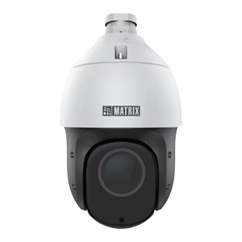
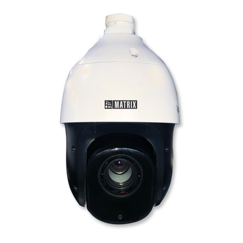
Matrix SATATYA PZCR50ML42CWP User manual

SATATYA PZCR50ML42CWP
Installation Guide

2
Documentation Disclaimer
Please read this guide first for correct installation and retain it for future reference. The
information in this guide is prevailing at the time of publication. However, Matrix Comsec reserves
the right to make changes in product design and specifications without prior notice.
Warranty
For product registration and warranty related details visit us at:
http://www.matrixcomsec.com/product-registration-form.html
Copyright
All rights reserved. No part of this Quick Installation Guide may be copied or reproduced in any
form or by any means without the prior written consent of Matrix Comsec.
Release date: August 29, 2023 9:23 AM

3
Table of Content
1. Package Contents....................................................................................................................................... 4
2. Cautions..................................................................................................................................................... 4
3. System Requirements ................................................................................................................................ 4
4. Hardware Overview ................................................................................................................................... 5
4.1 PTZ Camera with 5MP 42X Optical Zoom ............................................................................................ 5
4.2 B41 Wall Mount Bracket ...................................................................................................................... 6
5. Camera Dimensions................................................................................................................................... 7
6. Things you will need .................................................................................................................................. 8
7. Hardware Installation ................................................................................................................................ 8
7.1 PTZ Camera with 5MP 42X Optical Zoom ............................................................................................ 8
7.2 Adjusting the Camera Angle .............................................................................................................. 10
7.3 Wiring Details .................................................................................................................................... 10
7.4 How to Connect to Alarm Interface................................................................................................... 11
7.5 How to Connect the Water-proof Connector .................................................................................... 12
8. Recommended method of outdoor installation ...................................................................................... 13
9. Hardware Reset........................................................................................................................................ 14
10. Accessing the SATATYA Network Camera................................................................................................. 15
10.1 Assigning an IP Address ................................................................................................................... 15
10.2 Accessing from the Web Browser.................................................................................................... 17
11. Technical Specification............................................................................................................................. 20
12. Certifications............................................................................................................................................ 23
13. Disposal ................................................................................................................................................... 24
4
Thank you for purchasing SATATYA Network Camera. This Guide provides basic instructions on
installing and accessing SATATYA Network Camera. For more details, please refer to the System
Manual.
1. Package Contents
Before installation, please verify that all the necessary items are supplied in the box as the
package contents listed below. If any item is missing or damaged, please contact Matrix sales
representative.
Items
Quantity
Description
Default
SATATYA Network
Camera
1 PC
Power Adapter
1 PC
DC 24V (optional)
Bracket& Screw Pack
If purchased
Note:
The Ceiling Mounting Template and other Ceiling Mounting accessories like Pendant Pipe will not
be provided by Matrix.
2. Cautions
Do not expose the product to rain or moisture
Make sure the device is firmly fixed when mounting them on the wall or ceiling
Make sure that the power supply voltage is correct before using the camera
Never attempt to disassemble or modify the camera
3. System Requirements
Operating System: Windows XP/Vista/7/8/10/Server 2000/Server 2008
CPU: 1.66GHz or higher
RAM: 1G or higher
Graphic memory: 128MB or more
Internet protocol: TCP/IP (IPv4/IPv6)
Web Browsers: Internet Explorer 8.0 and above version, Mozilla Firefox, Google Chrome and Safari

5
4. Hardware Overview
4.1 PTZ Camera with 5MP 42X Optical Zoom
Note:
1) PoE and AC 24V is available for PTZ Camera power supply.
2) Built-in SD card slot can be seen after removing the 4 screws and open the front panel;

6
4.2 A41 Wall Mount Bracket
Accessories Map*
Note: External Corner Bracket, Pole Mount and Junction Box are accessories that can be used
according to your installation scenario but are not provided by Matrix.

7
5. Camera Dimensions

8
6. Things you will need
A Power Drill, Screwdriver Set, Pliers, Wire-cutter, Ladder.
Necessary Cabling
A Power Supply with the recommended output voltage of 24V DC. Use an Adapter to connect the camera to
the power outlet (optional, not supplied by Matrix).
7. Hardware Installation
For 5MP 42X Speed Dome Network camera, please mount it in a forward-facing position for more
accurate IVA function.
Recommendations:
1. Use a UL listed power supply unit marked “Class 2” or “LPS” or “PS2” and rated 12VDC, 2A min.
2. Make sure the wired LAN hub providing Power over the Ethernet (PoE) is in accordance with
IEEE 802-3af, shall be a UL listed device with the output evaluated as a limited power source as
defined in UL60950-1 or PS2 as defined in UL62368-1.
Installation Methods
Wall Mount
Ceiling Mount (the accessories are not provided by Matrix for this installation scenario)
7.1 PTZ Camera with 5MP 42X Optical Zoom
Step1: Check the wall or ceiling condition. Ensure that there is sufficient strength to avoid flaking.
It should be able to bear the weight eight times larger than the camera’s;
Step2: Use the wall or ceiling hanging holder to mark the holes. Drill 4 holes on the wall or ceiling;

9
Step3: Put the cables through the holder. Match the holder with the screw holes of the camera
body and secure them;
Step4: Make sure that the camera body has been correctly installed to the holder, and match the
holder to the holes on the wall or ceiling, then tighten up the screws.

10
7.2 Adjusting the Camera Angle
Camera angle can be adjusted via PAN Movement and Tilt Movement, refer to the table below for
PAN and Tilt Movement Range.
Parameter Name
PZCR50ML42CWP
PAN Range
360 degree endless
PAN Speed
Manual: 0.1°~400°/s
Preset: 400°/s
Tilt Range
0°~90°(Auto Flip)
Tilt Speed
Manual: 0.1°~320°/s
Preset: 320°/s
7.3 Wiring Details
1. AC 24V Cable: It is used for power supply.
3. Ethernet Port: It is used to connect the camera to the computer host or other network
equipment. When connecting the network cable, it is recommended that the network cable should
not be more than 100m long. Also used when you need to provide power to the Camera using PoE.
4. Audio Input/ Output Cable: You can connect the Audio Input device such as Mic to the Audio
Input cable of the camera. The audio when enabled will be recorded with the video and will be
available at the monitoring location. You may connect the Audio Output device such as Earphone
or Speaker to the Audio Output cable of the camera. This will generate audio received from the
network.
5. Alarm IN Cable: To detect alarm events you can connect a sensor device to the Alarm IN cable of
the camera.
6. Alarm OUT Cable: To get alerts on alarm you can connect the alarm sounding device such as
Hooter or Siren to the Alarm OUT cable of the camera.
Note:
If devices such as Mic and Speaker are connected to Audio IN and Audio OUT, you may need to
connect an external power source if their power requirements are not fulfilled with the camera
adapter.
If devices such as Sensor and small Buzzers are connected to Alarm IN and Alarm OUT, you may
need to connect an external power source if their power requirements are not fulfilled with the
camera adapter.

11
7.4 How to Connect to Alarm Interface
External interface of camera is as the following, you can refer to the picture to install the external
alarm device:
PIN1: Alarm Output NC/NO 24V DC 1A
PIN2: Alarm Output NC/NO 24V DC 1A
PIN3: Alarm Input NC/NO ≤12V
PIN4: Alarm Input NC/NO ≤12V

12
7.5 How to Connect the Water-proof Connector
Step1: Get the network cable through the screw nut, rubber ring and the screw bolt;
Step2: Insert the rubber ring into the screw bolt;
Step3: Connect the screw nut to the screw bolt;
Step4: Place the O-Ring on the network port connector;
Step5: Connect the RJ45 to the network port connector; tighten the screw bolt and the connector.
Note:
Please tightly wrap all cable-out interfaces with adhesive tape at last to prevent them from water.

13
8. Recommended method of outdoor installation
The picture below shows an example of outdoor installation:
The devices represented by numbers in the picture are explained as follows:
①Lightning rod
②Video surge arrester
③Telecommunication surge arrester
④Power surge arrester
⑤Grounding conductor (resistance no more than 4 ohms)
⑥Steel tube protector
Here are some notes for outdoor installation:
1) Never use the overhead line in open area.
2) Set the line under eave.
3) The signal line is at least 50 meters away from the high voltage.
4) Attach a lightning rod to the top of the pole on which the camera is going to be mounted.
5) Make sure that your camera is not at the top of the pole and must be installed within the
lightning rod below 45 degrees.
6) Make sure that system adopts equipotential grounding.

14
9. Hardware Reset
Step1: Press the reset button and hold on, then power on the network camera and the IR LEDs will
begin to twinkle;
Step2: Loosen the reset button, then the camera begins to reset;
Step4: It will take 1~3 minutes to complete the reset and the IP will turn into 192.168.1.126 (If the
IP does not change, please try again from step 1.);

15
10. Accessing the SATATYA Network Camera
The camera must be assigned an IP address to be accessible.
10.1 Assigning an IP Address
The Network Camera must be assigned an IP address to be accessible. The default IP address of
SATATYA Network Camera is 192.168.1.126.
You can either change the IP address of the camera via browser. Please connect the camera in the
same LAN of your computer.
10.1.2 Assign an IP Address via Browser
If the network segment of the computer and that of the camera are different, please follow the
steps to change the IP address:
Step1: Change the IP address of computer, here are two ways as below:
a. StartControl PanelNetwork and Internet ConnectionNetwork Connection
Local Area Connection, and double click it.
b. Click “Advanced”, and then click “IP settings” “IP address” “Add”. In the pop-up
window, enter an IP address that in the same segment with SATATYA network camera
( e.g. 192.168.1.126, but please note that this IP address shall not conflict with the IP
address on the existing network);

16
Step2: Open the browser. In the address bar, enter the default IP address of the camera:
http://192.168.1.126;
Step3: Enter the user name and password when the LOGIN page appears;
(Default user name: admin; Default password: admin)
Note:
(1) Password must be 8 to 32 characters long, contain at least one number and one letter.
(2) You can click the “forget password” in login page to reset the password by answering three security
questions when you forget the password, if you set the security questions in advance.

17
Step4: After login, please click “Configuration”“Basic Settings”“Network”“TCP/IP”. The
Network Settings page appears .
Step5: Change the IP address or other network values. Then click “Save” button;
Step6: The process of changing the default IP address is completed.
10.2 Accessing from the Web Browser
The camera can be used with the most standard operating systems and browsers. The
recommended browsers are Internet Explorer, Firefox, Chrome, Safari.
10.2.1 Access over IE Browser
Before using the browser to get access to your camera, you need to install the MsActiveX first. You
can refer the steps given below:
Step1: Open the IE browser and enter the IP address of the camera: http://192.168.1.126;
Step2: Enter the user name and password when the LOGIN page appears;
(Default user name: admin; Default password: admin)
Note:
(1)Password must be 8 to 32 characters long, contain at least one number and one letter.
(2)You can click the “forget password” in login page to reset the password by answering three security
questions when you forget the password, if you set the security questions in advance.
Step3: At the first time to log in the device, the browser will prompt to install Controls, please click
“Click here to download and install controls manually” as shown below;

18
Step4: Follow the prompts to install the Controls, when it`s finished, it will pop out a window as
below. Please click “Finish”and refresh the browser, then you will see the video.
If IE9 or higher version browser is used, it is suggested that the SATATYA camera web link should be
added as a trusted site. Refer to the instructions given below:
Step1: Start the IE9 or higher version browser, and select “Tools”→ “Internet Options”;
Figure8-14
Step2: Select “Security” to “Trusted”;

19
Figure 8-15
Step3: Enter the IP address of the camera in the blank and click “Add”;
Figure 8-16
Step4: Enter the IP address. After logging on Network Camera’s web GUI successfully, user is
allowed to view live video as follows.

20
11.Technical Specification
SATATYA PZCR50ML42CWP
General
Image Sensor
1/2.8" CMOS
Min. Illumination
WDR
120dB Super WDR
Shutter Time
1/100000s~1s
Digital Zoom
16X
Day/Night Mode
Day/Night/Auto/Customize/Schedule
S/N
>55dB
Lens
Focal Length
7~300mm,
42X Optical Zoom
Zoom Speed
Approx 7s (Wide-Tele)
Field of View
H43°~H2°/D53°~D2°
/V33°~V1°
Focus Control
Auto/Semi-Auto/Manual
Minimum Working Distance
1200/1500mm
(Wide/Tele)
Aperture
F1.8~F6.5
Iris Control
Auto
PTZ
Pan Range/Pan Speed
360°endless / Pan Manual Speed: 0.1°~400°/s, Pan Preset Speed:
400°/s
Tilt Range/Tilt Speed
0°~90°(Auto Flip) / Tilt Manual Speed: 0.1°~320°/s, Tilt Preset
Speed: 320°/s
Proportional Zoom
Support
Preset Quantity
300
Patrol
8 Patrols, up to 48 presets each patrol
Pattern
4 Patterns
Auto Tracking
Support
Power Off Memory
Support
Other Function
Auto Scan, Auto Home, Preset Freezing, 3D positioning, PTZ Limits,
Initial Position
IR
IR Distance
Up to 300m
IR Angle
Auto/Manual
Video
Max. Image Resolution
2592x1944
Primary Stream
60Hz: 30fps@(2592x1944),
45fps@(2048x1536),60fps@(1920x1080, 1280x960,
1280x720, 704x576)
50Hz: 25fps@(2592x1944),
45fps@(2048x1536),50fps@(1920x1080, 1280x960,
1280x720, 704x576)
Other manuals for SATATYA PZCR50ML42CWP
1
Table of contents
Other Matrix Security Camera manuals

Matrix
Matrix SATATYA PZCR20ML25CWP User manual

Matrix
Matrix SATATYA PZCR20ML25CWP User guide

Matrix
Matrix SATATYA PZCR20ML33CWP User guide

Matrix
Matrix SATATYA Professional Series User manual

Matrix
Matrix SATATYA PZCR50ML42CWP User guide

Matrix
Matrix SATATYA Professional Series User manual

Matrix
Matrix SATATYA Project Series User manual
Popular Security Camera manuals by other brands

Moxa Technologies
Moxa Technologies VPort P06HC-1V Series Quick installation guide

Axis
Axis M4206-V installation guide

Rugged CCTV
Rugged CCTV RB358 user manual

Dalsa
Dalsa Piranha4 Series user manual

Honeywell
Honeywell HCW2S2 Quick installation guide

stabo
stabo multifon WLAN indoor cam Quick start operating instructions