Matsushima MWLM-PR26HEx User manual

TMWLM-006E
Rev0:Sep.23,2016
−Contents−
Safety precautions ・・・・・・・・・・・・・・・・・・・・1
1.Overview・・・・・・・・・・・・・・・・・・・・・・・2
2.Measurement principle・・・・・・・・・・・・・・・・・2
3.Specifications ・・・・・・・・・・・・・・・・・・・・2
4.System configuration・・・・・・・・・・・・・・・・・・4
5.Dimensions・・・・・・・・・・・・・・・・・・・・・・6
6.Installation ・・・・・・・・・・・・・・・・・・・・・ 9
7.Wiring・・・・・・・・・・・・・・・・・・・・・・・・14
8.Start-up・・・・・・・・・・・・・・・・・・・・・・・15
9.Troubleshooting・・・・・・・・・・・・・・・・・・・・16
INSTRUCTION MANUAL FOR
MICROWAVE LEVEL METER
TYPE:MWLM-PR26HEx
(Code)
Liquid:MWLM-PR26H2G/FEx
Powder:MWLM-PR26H3G/F/S/SPEx
MWLM-PR26H7G/F/S/SPEx
※The operator should read this Instruction Manual carefully and handle the device correctly.
1-8-18Norimatsu-Higashi,Yahatanishi-ku,Kitakyushu807-0837Japan
PhoneNo.(8193)691-3731FaxNo.(8193)691-3735
http://www.matsushima-m-tech.com
E-mailsales@matsushima-m-tech.com

1
Safety precautions
Be sure to thoroughly read the instruction manual before using the products.
Keep the instruction manual in a safe, convenient location for future reference.
All or part of the contents described in this manual may be changed without any notice.
Due to our constant striving for further improvement of products, parts or products that differ from those
described in this manual may be substituted.
WARNING (Failure to observe this WARNING may cause a fatal or serious injury.)
・Be sure to confirm that any peripheral equipment does not move before installation work.
In addition, observe safety requirements for installation work where high-place work is expected.
・Be sure to turn off the power source before wiring, mounting and transportation work.
(Failure to observe this WARNING may result in an electric shock/ injury or equipment damage due to
short-circuit.)
・Carry out wiring work correctly with reference to a proper drawing.
・Never disassemble the equipment. (Failure to observe this WARNING may result in an electric shock.)
・Do not open the cover under an explosive environmental condition when power is entered.
(Failure to observe this WARNING may result in an injury or equipment damage.)
・Do not place or store the equipment in any hostile environmental place where it will be subjected to
direct sunlight, rain, water droplet, hazardous gas / water, etc..
・Never connect the GRAPHIC COM 3 of the optional sale at a dangerous place.
(Failure to observe this WARNING may result in an explosion at a dangerous place because it is not explosion
-proof circuit)
・Never connect the HART modem , equipment similar to it or measuring instruments to the HART interface
terminal of the main body panel part at a dangerous place.
(Failure to observe this WARNING may result in an explosion at a dangerous place because it is not explosion
-proof circuit.)
!
CAUTION (Failure to observe this CAUTION may cause a moderate injury or equipment damage.)
・Do not use the equipment for any purpose other than the original purpose of use.
・Be sure to confirm the specification of equipment and use the equipment within the range of specification.
(Mounting conditions such as temperature, power source, frequency, etc.)
・Make sure a correct wiring before applying power source.
・Do not have a shock or strong impact to the equipment.
(Failure to observe this CAUTION may result in equipment damage.)
・Be sure to connect necessary terminals (grounding, etc.).
・Remove all wiring to the equipment before doing electrical welding work near the equipment.
・Do not forcedly bend or pull the lead wire also do not use unnecessarily long wire.
・Tighten the cover, lead outlet, etc. properly so that dust, rainwater, etc. do not enter inside the equipment.
・Do not use the equipment under a corrosive condition (NH3, SO2, CI2, etc.).
・Be sure to tighten the cable grand so that outer air does not enter inside the equipment.
・When applying piping connection such as conduit, etc. instead of cable gland, apply putty or equivalents
On the cable entry so that outer air does not enter inside the equipment.
IMPORTANT (indicates notes or information to help customers.)
Limitations of Warranty:
・Warranty period shall be one year from the date of delivery (ex-factory).
・Any damage of any other products that have occurred for use of the equipment is not covered by
this warranty. Also any loss induced by failure or malfunction of the equipment is not covered by
this warranty.
・Failure or malfunction caused by following are not covered by this warranty:
a. Modification or repair by a party other than MATSUSHIMA’s authorized personnel, or replacement of
parts not recommended by MATSUSHIMA.
b. Inadequate storage, installation, use, inspection or maintenance that does not comply with specifications.
c. Cause for any peripheral equipment or device.
d. Accident beyond control and force majeure (fire, earthquake, flood, riots, etc.).
Lack of instructions to MATSUSHIMA for information or safety requirements that can be predicted only by
customers’ side.
This warranty conditions do not limit customers’ legal right.
Price for the equipment does not include any charge for services such as commissioning, supervising, etc..
!
!

2
1. Overview
Microwave level meter measures level of bulk solids and liquids in the storage vessels without physical
contact to measuring material. This model of level meter doesn't need separate output unit, which 4..20mA
current output signal is carried by same two wires for power supply.
2. Measurement principle
The level meter transmits microwaves at constant intervals, and receives echoes (reflection of transmitted
waves) from the surface of material under measurement. The time difference between transmission and
reception of microwave is processed by microcomputer to accurately determine level of stored materials.
3. Specifications
3-1.General Specifications
Table1. Standard specification (For Liquid)
Type MWLM-PR26HEx
Code MWLM-PR26H2GEx MWLM-PR26H2FEx
Explosion-proof construction (TIIS) Ex ia ⅡB T4 X
Rating
Intrinsically safe circuit: Equipment Voltage 25.4V
Equipment Current 86.8mA
Equipment Power 551mW
Internal inductance 0.7mH
Internal capacitance 5nF
Division of the
danger point
Housing Zone1,Zone2
Other than
a housing
Zone0, Zone1,Zone2
Power Supply(※1)DC24V (Please supply from safety barrier/KFD2-STC4-Ex1.)
Power consumption Max.540mW
Antenna Horn (L150mm)
Mounting(※2)G1 1/2 thread JIS5K50A flange
Dead Zone 0.5m below the antenna
Max Measurable Distance(※3)20m
Transmitting frequency Approx. 26GHz
Transmitting cycle Every 83ms
Bean angle(-3dB)Approx. 18deg.(Approx.36deg. side beam)
Resolution 1mm
Allowable Fluctuation Rate 10cm/s
Accuracy
(※3)
Repeatability Within 2m or less:±30mm
Within 2m or more:±20mm or ±0.04% of measurement range (Whichever is greater)
Temp. error 0.06%/10K
Ambient temp.(※4) −20℃〜+50℃
Measured fluid temp. −40℃〜+100℃
Allowable pressure 1MPa 0.5MPa
Protection
(※5)
Housing ADC
Boss SUS304
Antenna SUS316L
Protection(※5)IP67(Housing)
Lead outlet 1-G1/2 (Applicable size:8〜12mm)
Output signal DC4 to 20mA×1 (Resistive load Max.499)
Mass Approx. 1.9kg Approx. 2.2kg
Accessories(option)Data communication cable (MHM-01)
PC Adjustment software (MDTM)

3
Table2. Standard specification (For Powder)
Type MWLM-PR26HEx
Code MWLM-PR26H3
GEx/FEx/SEx/SPEx
MWLM-PR26H7
GEx/FEx/SEx/SPEx
Explosion-proof construction (TIIS) Ex ia ⅡB T4 X
Rating
Intrinsically safe circuit: Equipment Voltage 25.4V
Equipment Current 86.8mA
Equipment Power 551mW
Internal inductance 0.7mH
Internal capacitance 5nF
Division of the
danger point
Housing Zone1,Zone2
Other than
a housing
Zone0, Zone1,Zone2
Power Supply(※1)DC24V (Please supply from safety barrier/KFD2-STC4-Ex1.)
Power consumption Max.540mW
Antenna Horn(L200mm) Horn(L440mm)
Mounting(※2)
G:G1 1/2 thread
F:JIS5K65A flange
S:JIS10K100A swiveling flange
SP:JIS10K100A Standard swiveling flange
G:G1 1/2 thread
F:JIS10K100A flange
S:JIS10K100A swiveling flange
SP:JIS10K100A Standard swiveling flange
Dead Zone 0.5m below the antenna
Max Measurable Distance(※3)35m 70m
Transmitting frequency Approx. 26GHz
Transmitting cycle Every 83ms
Bean angle(-3dB)Approx.14°
(Approx.28deg. side beam)
Approx.8°
(Approx.16deg. side beam)
Resolution 1mm
Allowable Fluctuation Rate 10cm/s
Accuracy
(※3)
Repeatability Within 2m or less:±30mm
Within 2m or more:±20mm or ±0.04% of measurement range (Whichever is greater)
Temp. error 0.06%/10K
Ambient temp.(※4)−20℃〜+50℃
Measured fluid temp. −40℃〜+100℃
Allowable pressure G:1MPa,F:250kPa,S:10kPa,SP:1MPa
Protection
(※5)
Housing ADC
Boss SUS304
Antenna SUS316L
Protection(※5)IP67(Housing)
Lead outlet 1-G1/2 (Applicable size:8〜12mm)
Output signal DC4 to 20mA×1 (Resistive load Max.499)
Mass G:app. 2.7kg,F:app.5.3kg,S:app.6.0kg, SP:app.9.0kg
Accessories(option)Data communication cable (MHM-01), PC Adjustment software (MDTM)
※1) Power supply ripple voltage must be less than 0.2Vp-p.
Noise and surges should not be interfered. (Recommended)
※2) When mount on a short stand pipe, install the level meter so that the end of the antenna protrude
from the short stand pipe.
※3) The measurement range and accuracy are guaranteed only when, antenna is pointed at an angle
perpendicular to the material surface, temperature is normal (15℃),
permittivity is more than two at high pressure, and no any presence of airborne dust, vapor,
and agitated foam.
If these conditions are not satisfied, the measurement range and accuracy may differ according to
the measurement conditions.
※4) Ensure that freezing and/or condensing will not occur inside the electronic unit.
※5) The product meets the test of the Japanese Industrial Standards JIS C0920「Degrees of protection
provided by enclosures」. (Refer to 5. Dimensions with respect to the application range)
Take care that water may enter and damage the equipment, if lead outlet not tighten firmly or loosen.
When the equipment operated in the presence of process gases and/or fluids, those materials may
penetrate through resin of cone antenna and damage the equipment,
specially corrosive gases such as H2S, HCl and HF.
4
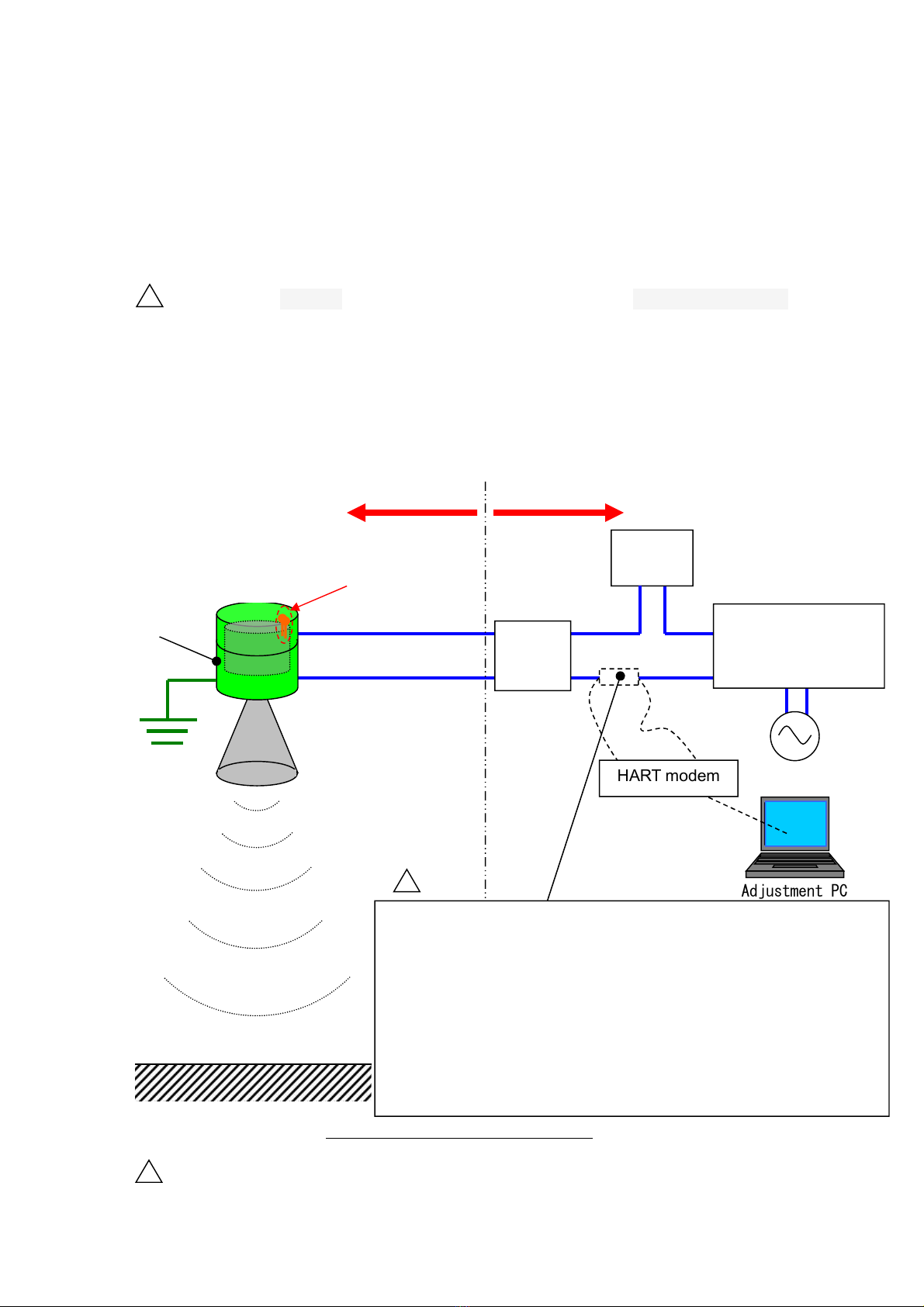
4. System configuration
This level measurement system is configured by the level meter and a safety barrier
(referring to the following page).
The level meter can be mounted at a dangerous place and a safety barrier can be mounted at
a non-dangerous place.
Division of the dangerous spot in the danger place
Housing Zone1,Zone2
Other than a housing Zone0, Zone1,Zone2
IMPORTANT:Refer to the division of the dangerous spots also described in page 10.
・Output signal :DC4〜20mA
・Resistive load :Max. 499
・Applicable cable size :0.3〜1.25mm2(AWG22〜16)
(the size of the acceptable cable is max.1.25mm2)
・Ground wiring(D-class grounding):1.25 mm2
WARNING:Do not connect the Data communication cable to the Adjustment communication check
pin at a dangerous place.
Failure to observe this WARNING may result in an explosion because it is not
explosion proof circuit.
Ammet
AC−DC Converter
(DC24V power)
AC power
+
−
(D-class
grounding)
Fig.1System configuration example
HART modem
AdjustmentPC
Level Meter
−
+
Balanced type
Shielded wire
Hazardous area A non-hazardous area
Housing
IMPORTANT:When you confirm a measurement wave and change
setting in the adjustment PC, other than the optional PC
Adjustment software and the Data communication
cable , a loading resistor of at least 250 Ohm is
necessary.
But when the input load of a safety barrier is more
than 250 Ohm, a loading resistor is unnecessary.
Refer to the following page and select a safety barrier.
HART check pin
!
!
!
Safety
barrier

5
・Withstand voltage test
Do not perform the withstand voltage test because the following withstand voltage test do not apply.
A test point of the withstand voltage(between the terminal 1 and the earth terminal, beween the terminal 2
and the earth terminals)
Test condition:Test voltage AC500V(effective value) must bemaintained for a mimute,
leakage current must be less than 5mA(effective value)
・Selecting condition of a safety barrier
Select a safety barrier passing the Type Examination only with it ,satisfying the following conditions and being
isolated between the input and the output circuits.
(1) Safety holding rating
The maximum voltage Uo of an intrinsic safety circuit must be less than 25.4V.
The maximum current Io of an intrinsic safety circuit must be less than 86.8mA.
The maximum power Po of an intrinsic safety circuit must be less than 551mW.
(2) Performance sorting and group of electric apparatus
Performance sorting ia
Group of electric apparatus ⅡB,ⅡC
(3) Relation of permissible inductance(Lo) of an intrinsic safety circuit and permissible capacitance (Co) of an
intrinsic safety circuit to inductance(Lw) and capacitance (Cw) of external wiring of an intrinsic safety circuit
Permissible inductance(Lo) of an intrinsic safety circuit ≧(0.7mH+Lw)
Permissible capacitance (Co) of an intrinsic safety circuit ≧(5nF+Cw)
[Recommended safety barrier]
Type:KFD2-STC4-Ex1(name of the maker:PEPPERL+FUCHS)
WARNING:The operation power supply of a safety barrier is DC24V.
The input load is more than 250 Ohm.
But when the adjustment PC is connected to the input terminal side, the configuration of the
level meter and a safety barrier would not be an intrinsic safety circuit.
Therefore, connect the adjustment PC to the output terminal side.
The connection sample using the recommended safety barrier is described in page 14.

6
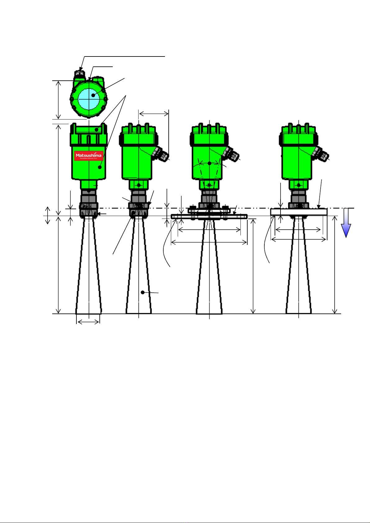
5. Dimensions (Units : mm)
Fig. 2. External dimensions for liquid type
※Refer to external dimensions for measurement reference point.
Basically upper part of mounting compartment is measurement reference point.
※Protection grade IP20 is applied to the structure from the antenna mounting screw hole face to the
antenna side.
When the closing plug mounted on the purge hole is removed and the air pipe is mounted, protection
grade IP20 is applied to the structure from the purge hole to the antenna side.
20
(104)
(82)
(255)
150
(45)
Transparent window: PC
Earth terminal
(
M4
)
Lead outlet G1/2
Cable 8
〜
12mm
G1 1/2
Purge hole
G1/8
Hex-head
opposite side 50
BOSS
:SUS304
Antenna:
SUS316L
Housing/Cover: ADC
Measurement
reference point
(14)
Flange:
SUS304
(J
IS5k50A
PCD120
130
4-19
Mounting hole
【Code:MWLM-PR26H2 series】
Protection
IP20
Protection
IP67
7
Fig. 3-1. External dimensions for solid type
※Refer to external dimensions for measurement reference point.
Basically upper part of mounting compartment is measurement reference point.
※Protection grade IP20 is applied to the structure from the antenna mounting screw hole face to the
antenna side.
When the closing plug mounted on the purge hole is removed and the air pipe is mounted, protection
grade IP20 is applied to the structure from the purge hole to the antenna side.
20
(104)
(82)
(255)
200
(58)
Transparent window: PC
Earth terminal
(
M4
)
Lead outlet G1/2
Cable 8
〜
12mm
G1 1/
2
Purge hole
G1/8
Boss
:SUS304
Antenna:
SUS316L
Housing/Cover: ADC
(28)
(14)
10
(192)
(206)
Max.10°
Max.10°
JIS5K65A
SUS304
PCD17
210
PCD130
155
8-19
Mounting hole
4-15
Mounting
hole
Protection
IP67
【Code:MWLM-PR26H3 series】
Measurement
reference point
JIS10K100A
flange with
Swivelling
mechanism
SUS304
Hex-head
opposite side
50
Protection
IP20

8
Fig. 3-2. External dimensions for solid type
※Refer to external dimensions for measurement reference point.
Basically upper part of mounting compartment is measurement reference point.
※Protection grade IP20 is applied to the structure from the antenna mounting screw hole face to the
antenna side.
When the closing plug mounted on the purge hole is removed and the air pipe is mounted, protection
grade IP20 is applied to the structure from the purge hole to the antenna side.
20
(104)
(82)
(255)
441
(98)
Transparent window: PC
Earth terminal
(
M4
)
Lead outlet G1/2
Cable 8
〜
12mm
G1 1/2
Purge hole
G1/8
Boss
:SUS304
Antenna
:SUS316L
Housing/Cover: ADC
(28)
10
10
(433)
(451)
Max.10°
Max.10°
JIS10K100A
SUS304
PCD17
5
210
PCD175
210
8-19
Mounting hole
8-19
Mounting
hole
【Code:MWLM-PR26H7 series】
Protection
IP67
Protection
IP20
Measurement
reference point
JIS10K100A flange
with Swivelling
mechanism
SUS304
Hex-head
opposite side
50

9
6. Installation
6-1. Division of the dangerous spot and temperature range
Code:MWLM-PR26H series
※Protection grade IP20 is applied to the structure from the antenna mounting screw hole face to the
antenna side.
When the closing plug mounted on the purge hole is removed and the air pipe is mounted, protection
grade IP20 is applied to the structure from the purge hole to the antenna side.
Fig.3.Division of the dangerous spot and temperature range
(Division of the dangerous spot)
Zone0
Zone1
Zone2
(Division of the dangerous spot)
Zone1
Zone2
(Ambient temp.)
−20℃〜+50℃
(Measured fluid temp.)
−40℃〜+100℃
(Protection)
IP67
(Protection)
IP20

10
6-2. Installation
Fig. 4. Installation for liquid and for solid
・If material surface enter to the blind sector, a stand pipe shall be used to ensure that material surface
can not reach the blind sector of the level meter. But if the material surface will not enter the blind sector,
then stand pipe should not be used.
・If length of stand pipe is longer than required, such that antenna end is not protruded from stand pipe,
then it causes malfunction of instrument.
・When required stand pipe length is longer than antenna, please use cone shape stand and ensure
radiation angle including the side beam.
Keep radiation free of interference from the stand pipe.
【Recommended height of stand pipe】
Solid: The end of the horn antenna must be protruded a minimum of 10mm from the stand pipe.
Liquid: The end of the antenna must be protruded a minimum of 25mm from the stand pipe.
【Calculation of radiation angle expansion】
Solid :Distance from meas. reference point × tan16°+98 (Antenna diameter)
Solid :Distance from meas. reference point × tan28°+56 (Antenna diameter)
Liquid:Distance from meas. reference point × tan48°+45 (Antenna diameter)
100%(Radiation angle)
50
%(
Side beam
)
Fig. 5. Radiation angle and side beam reference
Blind sector
0.3m
≧
10
≧
10
4
5
98
Blind sector
0.5m
≧
10
5
6
Blind sector
0.5m

11
6-3. Mounting direction
・At the application with repose angle and the mounting position near the sidewall etc, the
reflection intensity of Level Meter may weaken or the noise reflection is likely to occur.
As a countermeasure, the change of mounting direction can improve it in some cases.
Level Meter has an marking at the reference position of electric field direction on Adapter
If the direction of electric field is adjusted based on this marking, the reflection intensity
may increase or the noise reflection may reduce.
Turn and adjust it to the direction where the reflection wave is the largest and the noise reflection is
the least, checking the reflective condition.
6-4. Installation precautions
・Set the value of 100%(20mA) level so that the blind sector is secured. Setting the 100%(20mA)
level within the blind sector will cause a
malfunction of the instrument.
・Avoid too long stand pipe to prevent malfunction of the instrument.
Long stand pipeAntenna burying
Blind sector
Fig. 7. Installation precaution (1)
Turn around the flange in order to change the dot direction.
Fig.6 Mounting direction
Marking
Marking Point
E: Electric field
direction
Adapter
12
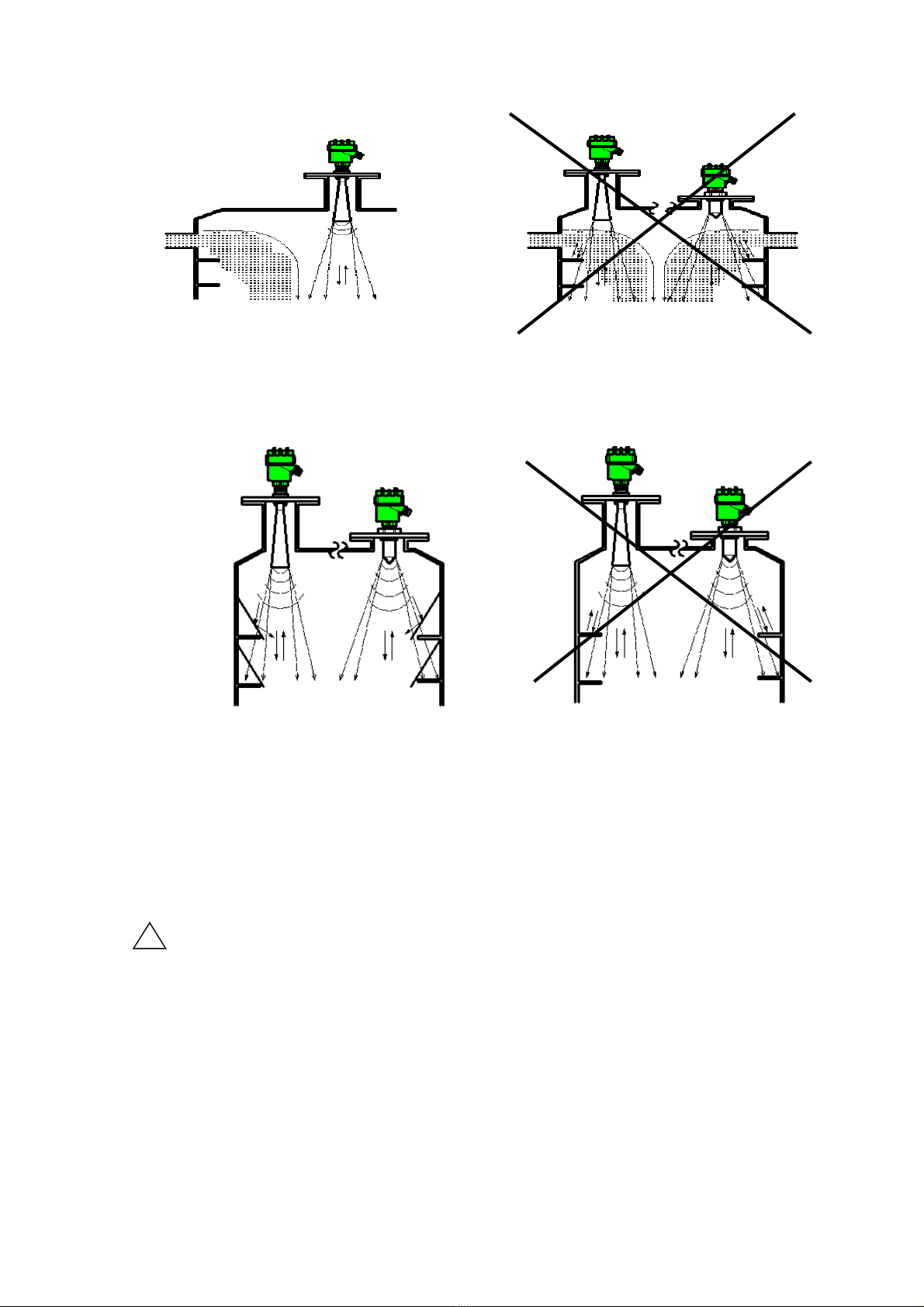
・Do not install instrument close to inlet of material under measurement.
・Do not install any interfering instruments within the side beam, because reflections from beams, pipes,
and other supports within the tank will cause false echoes.
・Provide shielding to minimize noise or unwanted reflections, when crossbeams, and other supports
are installed within the tank.
【False reflections】
In environments where interfering signals are generated, level meter may indicate incorrect
measurements results. False reflections up to a certain level of strength can be suppressed by
executing the echo learning function. However, the level meter's installed position must be changed if
true echoes cannot be received or if the reflection level (measured in dB) is extremely low. When there
are obstructions such as crossbeams, pipes, or level switches in the tank, install the level meter in a
position where there is no obstruction within its radiation angle.
Important:It is not possible to specify the range of false reflections in dB that can be
suppressed by the learning function because the level of true echo from the
surface of material differs depending on the level meter installation conditions and
measuring material type. The general guideline for the level of false reflections that
can be suppressed by the learning function is one third (1/3) of true echo level.
Fig. 9. Installation precaution (3)
!
Fig. 8. Installation precaution (2)
13
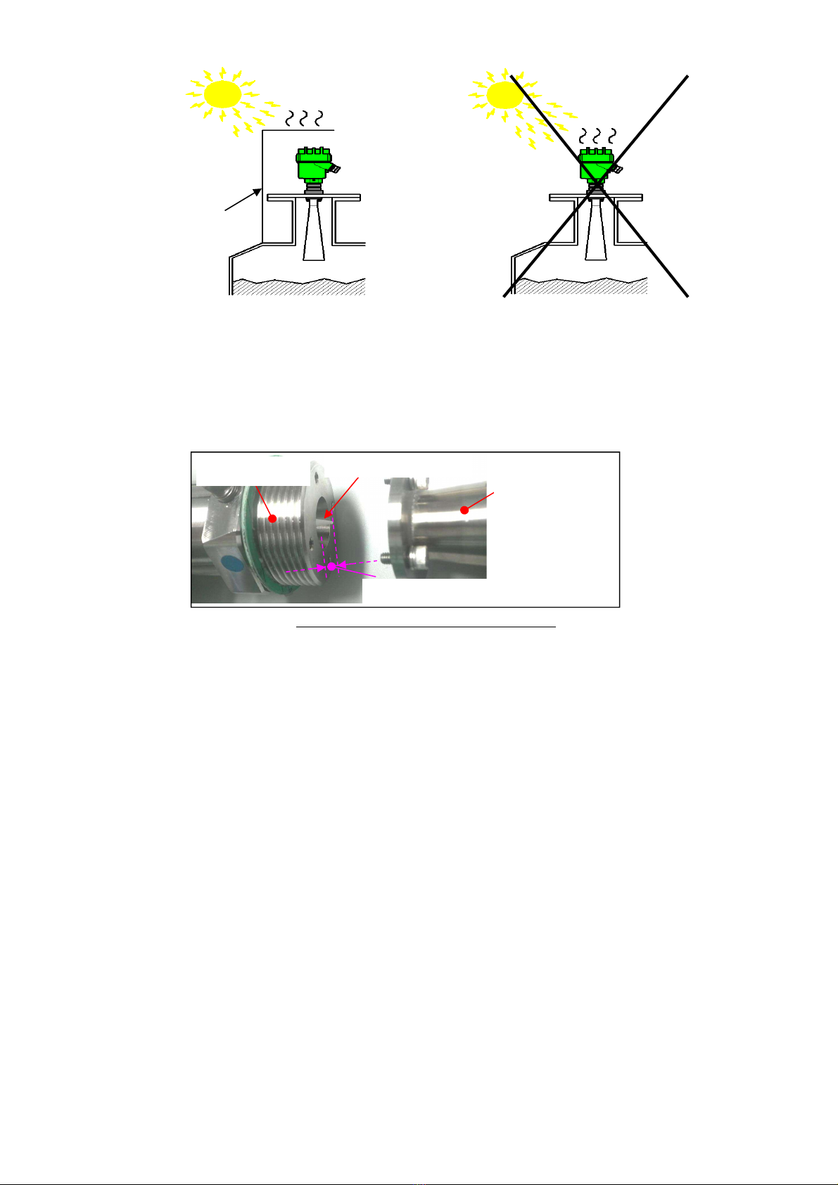
・Install protection such as a simple roof above the Level Meter to avoid exposure to direct sunlight.
・There is a structural equipment that the cone antenna goes out than the attaching portion when the
horn antenna is detached by maintenance etc.
Please do not put the cone antenna part doing below after detaching the horn antenna.
The cone antenna might be damaged, and it influence the measurement.
Simplecover
Fig. 10. Installation precaution (4)
C
one antenna
H
orn antenna
Mounting part
※It goes out.
Fig11. The horn antenna was detached.

14
7. Wiring
7-1. Unscrew the cover. (Rotate counterclockwise)
7-2. Open the wire entry of terminal block by pushing
on the actuating lever with flat screwdriver.
(Recommended flat screwdriver:
Axis diameterφ3mm and blade tip size 2.6mm)
7-3. Insert wires as shown on the panel, positive (+) to terminal
entry No.1 and negative (-) to terminal No.2.
Please wire so that there is no mistake.
Release actuating lever of the terminal.
7-4. Connect the ground wire to internal earth ground terminal.
7-5. Screw the cover on tightly.
Important:
The size of the acceptable cable is
max. 1.25mm2 (0.3mm2to 1.25 mm2).
(AWG22 to 16)
Warning:
Do wiring when the instrument is powered OFF.
Avoid short circuit and reverse polarity.
The instrument must be supplied with
DC power supply, do not apply different voltage.
Tighten the cover and lead outlet firmly after
wiring completed.
Warning:
Do not connect the Data communication cable to the
Adjustment communication check pin at a dangerous
place.
HART check pin
Use a wire more than 1.25sq as an earth wire.
!
!
Fig. 12. Cover detaching
Fig. 13. Wiring technique
Flat screwdriver
Cover
Lead outlet
PC
(
D
-
class groundin
)
LCD
HARTI/F
DC24V
4..20mA
MWLM-PR26
12
+-
Ammeter
DC4〜20mA
AC−DC
converter
(DC24V)
DC4
〜
20mA
DC24V
DC4〜20mA
Safety barrier
KFD2-STC4-Ex1
3
1
(
−
)
(
+
)
15
14
9
8
7
HART
(
−
)
(
+
)
(
−
)
(
+
)
ACPower
Max.500
Ω
Hazardous area
A non
-
h
azardous area
!
Fig.14.
Connection example for KFD2
-
STC4
-
Ex1

15
9. Start - up
Fig.15. Start - up
Level meter
installation
Wiring
Wiring
confirmation
Power supply
turning on
Error code output
Distance display
confirmation
Adjsutment with PC
Ready to start
level measurement
OK?
OK?
OK?
Y
N
Y
N
Y
70m
0m Reflection (dB)
100%(20mA)
0%(4mA)
Reflection echo
Fig. 16. Measurement range
※"LCD adj. unit" ,"Software for PC adjustment" and
"HART modem" are optional products.
※For the error code details, please refer to “Instruction manual for
LCD adjustment unit” and “Operating manual for adjustment
software Matsushima DTM”.
Power supply
confirmation
N

16
11.Troubleshooting
If you encounter any problems, first check if they are described in this section, then execute suggested
corrective actions.
Table 3. Troubleshooting
Table 4. Periodic inspection
No. Item Descriptions Interval (standard)
1 Check of
appearance
・Confirm whether there is damage on housing etc.
・Tighten the cover and lead outlet
・Tighten the bolt for installation fixture
Every 12 months
2 Check of antenna ・Clean the antenna (Solid: Inside,Liquid: Outside) Every 6 to 12 months
Important: Standard periodic inspection interval differs depending on measurement
condition and measuring material.
No. Problem Check the following Corrective actions
1 Powered ON the device, but
screen is blank
・Are wiring connections correct ?
・Check whether the power is supplied to
the device?
・Correct the wiring
・Supply power to the device
2 Measured level reading higher
than material level
・Are there any obstructions between
antenna and material surface to be
measured ?
・Are there any inlet streams of material
under measurement within the
radiation angle
・Execute echo learning to mask
false echo from the obstacle
・Change the level meter position
3 Measured level reading lower
than material level
・Check whether the material surface
entered to the blind sector ?
・Change level meter installation
!
Other Matsushima Measuring Instrument manuals


Popular Measuring Instrument manuals by other brands


Keithley
Keithley 236 Service manual

Camille Bauer
Camille Bauer LINAX PQ5000MOBCL MULTI-PQ System handbook

Triplett
Triplett RHT02 user manual

Endress+Hauser
Endress+Hauser Prosonic S FMU95 operating instructions

Codex
Codex CDX-36050 Getting started guide

Interacoustics
Interacoustics MT10 Instructions for use


