Matsushita Electric DVD-S42E User manual

ORDERNO.CHM0602002CE
DVDPlayer
DVD-S42E / DVD-S42EG
DL4.1Mechanism Series
Color
(S).......................Silver Type
(K).......................Black Type
SPECIFICATIONS
Specifications
Power supply: AC230 V, 50 Hz
Power consumption: 11 W
Power consumption instandbymode:
1W(approx.)
Dimensions: 430 (W) × 251 (D) × 43 (H) mm
Mass: 2.2kg(approx.)
Signal system: PAL625/50, PAL525/60, NTSC
Operating temperature range: + 5to+ 35 °C
Operating humidityrange: 5to90 %RH (no
condensation)
Discs played[8cm (3” ) or12 cm (5” )]:
(1) DVD (DVD-Video, DivX*6,7)
(2) DVD-RAM (DVD-VR, JPEG*4,7, MPEG4*5,7, DivX*6,7,
MP3*2,7)
(3) DVD-R (DVD-Video, DVD-VR, JPEG*4,7, MP3*2,7, DivX*
6,7, MPEG4*5,7)
DVD-R DL(DVD-Video, DVD-VR)
(4) DVD-RW(DVD-Video, DVD-VR, JPEG*4,7, MP3*2,7,DivX*
6,7, MPEG4*5,7)
(5) +R/+RW(Video)
+R DL(Video)
(6) CD, CD-R / CD-RW(CD-DA, VideoCD, SVCD*1, MP3*2,7,
WMA*3,7, JPEG*4,7 , MPEG4*5,7, DivX*6,7,
HighMATLevel 2(Audioand Image))
*1 Conforming toIEC62107
*2 MPEG-1Layer 3, MPEG-2Layer 3
*3 WindowsMediaAudioVer.9.0L3
1
PDFcreated withpdfFactoryProtrialversion www.pdffactory.com

Not compatiblewithMultipleBit Rate(MBR)
*4 Exif Ver2.1JPEG Baselinefiles
Picture resolution: between160 × 120 and 6144 × 4096
pixels(Sub sampling is4:0:0, 4:2:2, 4:2:0, 4:4:4)
*5 MPEG4datarecordedwiththePanasonicSD multi
cameras orDVD videorecorders conforming toSD
VIDEO specifications(ASFstandard) /MPEG4(Simple
Profile) videosystem/G.726 audiosystem
*6 Playsall versionsof DivX video(including DivX6) with
standardplayback of DivX mediafiles. Certifiedtothe
DivX
Home Theater Profile.
GMC (Global Motion Compensation) not supported.
*7 Thetotal combinedmaximumnumber of recognizable
audio, picture and videocontentsand groups: 4000
audio, picture and videocontentsand 400 groups.
Videooutput:
Output level: 1Vp-p(75 )
Output terminal: Pinjack (1system)/AV
S videooutput:
Y output level: 1Vp-p(75 )
C output level: NTSC; 0.286 Vp-p(75 )
PAL; 0.300 Vp-p(75 )
Output terminal: AV
Component videooutput: [NTSC: (480)p/(480)i,
PAL: (576)p/(576)i]
Y output level: 1Vp-p(75 )
P B output level: 0.7Vp-p(75 )
P R output level: 0.7Vp-p(75 )
Output terminal: Pinjack (Y: green, P B : blue,
P R : red)
Number of terminals: 1system
RGB videooutput:
R output level: 0.7Vp-p(75 )
G output level: 0.7Vp-p(75 )
B output level: 0.7Vp-p(75 )
Output terminal: AV
Videoperformance:
Horizontal resolution: More than500 lines
VideoS/N ratio: More than65dB
Audiooutput:
Output level: 2Vrms (1kHz, 0dB)
Output terminal: Pinjack/AV
Number of terminals:
2channel: 1system
Audioperformance:
(1) Frequencyresponse:
DVD (linear audio): 4Hz-22 kHz (48 kHz sampling)
4Hz-44 kHz (96 kHz sampling)
CD audio: 4Hz-20 kHz
2
PDFcreated withpdfFactoryProtrialversion www.pdffactory.com

(2) S / N ratio:
CD audio: 115 dB
(3) Dynamicrange:
DVD (linear audio): 102 dB
CD audio: 98 dB
(4) Total harmonic
distortion:
CD audio: 0.003 %
Digital audiooutput:
Coaxial digital output: Pinjack
Pickup
Wavelength: 662 nm/ 785 nm
Laser power: CLASS 2/ CLASS 3A
Note:
Specificationsare subject tochangewithout notice.
Mass and dimensionsare approximate.
Solder:
Thismodel uses leadfree solder (PbF).
2006 Matsushita ElectricIndustrial CO., Ltd. All rights reserved.
Unauthorized copying and distribution isaviolation of law.
3
PDFcreated withpdfFactoryProtrialversion www.pdffactory.com

1. IMPORTANT SERVICE INFORMATION
1.1. Notes
Whenyou replace EEPROM orexchange MODULE PCB, you have totake “Manual for
customer” tothe customerwithunit. (alsointhe case of unit exchange)
Please take and use “Manual forcustomer” frombelow.
1. Come with MODULE PCB or EEPROM(Service part).
2. Make aphotocopysection 1.3. “Manual for customer” on this
service manual.
“Manual forcustomer” has important information for“DivX Video-on-Demand Service” user.
Please don’t forget take it tothe customerwithunit !
1.2. About DivX
1.2.1. DivX
A videocompression format developedbyDivXNetworks, Inc. that compresses videofiles
without anyconsiderable loss of videoquality.
1.2.2. About DivX Video-on-Demand Content
4
PDFcreated withpdfFactoryProtrialversion www.pdffactory.com

1.3. Manual for Customer
2. SAFETY PRECAUTIONS
2.1. GENERALGUIDELINES
1. When servicing, observe the original lead dress. Ifashort circuit
isfound, replace all parts which have been overheated or
damaged bythe short circuit.
2. After servicing, see to itthat all the protective devices such as
insulation barriers, insulation papers shields are properly
installed.
3. After servicing, make the following leakage current checks to
prevent the customer from being exposed to shock hazards.
2.1.1. LEAKAGE CURRENTCOLD CHECK
1. Unplug the AC cord and connect ajumper between the two
prongs on the plug.
2. Measure the resistance value, with an ohmmeter, between the
jumpered AC plug and each exposed metalliccabinet part on the
equipment such as screwheads, connectors, control shafts, etc.
When the exposed metallicpart has areturn path to thechassis,
the reading shouldbe between 1M and 5.2M . / When the
exposed metal does not have areturn path to the chassis, the
reading must be . Figure 1
2.1.2. LEAKAGE CURRENTHOTCHECK (See Figure 1 .)
6
PDFcreated withpdfFactoryProtrialversion www.pdffactory.com

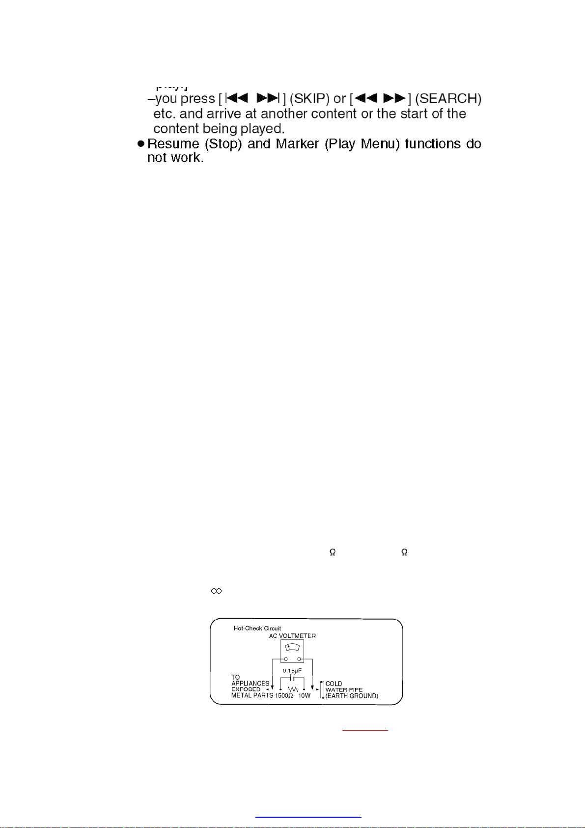
1. Plug the AC cord directlyinto the AC outlet. Donot use an
isolation transformer for thischeck.
2. Connect a1.5k , 10 watts resistor, inparallel with a0.15 F
capacitors, between each exposed metallicpart on the set and a
good earth ground such as awater pipe, as shownin Figure 1.
3. Use an AC voltmeter, with 1000 ohms/voltor more sensitivity, to
measure the potential across the resistor.
4. Check each exposed metallicpart, and measure the voltage at
each point.
5. Reverse the AC plug inthe AC outlet and repeat each of the above
measurements.
6. The potential at anypoint shouldnot exceed 0.75 volts RMS. A
leakage current tester (Simpson Model 229 or equivalent) maybe
used to make the hot checks, leakage current mu3st not exceed 1/
2milliamp. Incase ameasurement isoutsideof the limits
specified, there isapossibilityof ashock hazard, and the
equipment shouldbe repaired and rechecked before itisreturned
to the customer.
3. PREVENTION OF ELECTRO STATIC DISCHARGE
(ESD) TO ELECTROSTATICALLY SENSITIVE (ES)
DEVICES
Some semiconductor(solidstate) devices canbe damagedeasilybystatic electricity. Such
components commonlyare calledElectrostaticallySensitive (ES) Devices. Examples of typical
ES devices are integratedcircuits and some field-effect transistorsand semiconductor"chip"
components. The following techniques shouldbe usedtohelpreduce the incidence of
component damage causedbyelectrostatic discharge (ESD).
1. Immediatelybefore handling anysemiconductor component or
semiconductor-equipped assembly, drainoff anyESDon your
bodybytouching aknownearth ground. Alternatively, obtainand
wear acommerciallyavailabledischargingESDwrist strap, which
shouldbe removed for potential shock reasons prior to applying
power to the unitunder test.
2. After removing an electrical assemblyequipped with ES devices,
place the assemblyon aconductive surface such as alminum foil,
7
PDFcreated withpdfFactoryProtrialversion www.pdffactory.com

to prevent electrostaticcharge buildup or exposure of the
assembly.
3. Use onlyagrounded-tipsoldering iron to solder or unsolder ES
devices.
4. Use onlyan anti-staticsolder removal device. Some solder
removal devices not classified as "anti-static(ESDprotected)"
can generate electrical charge sufficient to damage ES devices.
5. Donot use freon-propelled chemicals. These can generate
electrical charges sufficient to damage ES devices.
6. Donot remove areplacement ES device from its protective
package until immediatelybefore you are readyto install it. (Most
replacement ES devices are packaged with leads electrically
shorted together byconductive foam, alminum foil or
comparableconductive material).
7. Immediatelybefore removing the protective material from the
leads of areplacement ES device, touch the protective material to
the chassisor circuitassemblyinto which the device will be
installed.
Caution
Besure no power isapplied to the chassisor circuit, and observe
all other safetyprecautions.
8. Minimize bodilymotions when handling unpackaged replacement
ES devices. (Otherwise hamless motion such as the brushing
together of your clothes fabricor the lifting of your foot from a
carpeted floor can generate staticelectricity(ESD)sufficient
todamage an ES device).
4. PRECAUTION OF LASER DIODE
8
PDFcreated withpdfFactoryProtrialversion www.pdffactory.com

5. SERVICE CAUTION BASED ON LEGAL
RESTRICTIONS
5.1. General description about Lead Free Solder (PbF)
The leadfree solderhas beenusedinthe mounting process of all electrical components on the
printedcircuit boards usedforthis equipment inconsidering the globallyenvironmental
conservation.
The normal solderis the alloyof tin(Sn) and lead(Pb). Onthe otherhand, the leadfree solderis
the alloymainlyconsists of tin(Sn), silver(Ag) and Copper(Cu), and the melting point of the
leadfree solderis higherapprox.30°C (86°F) more thanthat of the normal solder.
Definition of PCB LeadFree Solderbeing used
Service caution forrepairwork using LeadFree Solder(PbF)
-The lead free solder has to be used when repairing the equipment
for which the lead free solder isused. (Definition: The letter of
“PbF” isprinted on the PCB using the lead free solder.)
-To put lead free solder, itshouldbe well molten and mixed with the
original lead free solder.
-Remove the remaining lead free solder on the PCB cleanlyfor
9
PDFcreated withpdfFactoryProtrialversion www.pdffactory.com

soldering of the new IC.
-Since the melting point of the lead free solder ishigher than that of
the normal lead solder, ittakes the longer time to meltthe lead
free solder.
-Use the soldering iron (more than 70W) equipped with the
temperature control after setting the temperature at 350±30°C(662
±86°F).
RecommendedLeadFree Solder(Service Parts Route.)
The following 3 types of leadfree solderare available through the service parts route.
-RFKZ03D01K-----------(0.3mm 100g Reel)
-RFKZ06D01K-----------(0.6mm 100g Reel)
-RFKZ10D01K-----------(1.0mm 100g Reel)
Note
*Ingredient: tin(Sn) 96.5%, silver (Ag) 3.0%, Copper (Cu) 0.5%,
Cobalt(Co) / Germanium (Ge) 0.1to 0.3%
6. PREVENTION OF STATIC ELECTRICITY
DISCHARGE
The laserdiode inthe traverse unit (optical pickup) maybrake downdue tostatic electricityof
clothes orhumanbody. Use due caution toelectrostatic breakdownwhenservicing and
handling the laserdiode.
6.1. Grounding for electrostaticbreakdownprevention
Some devices suchas the DVD playeruse the optical pickup (laserdiode) and the optical
pickup will be damagedbystatic electricityinthe working environment. Proceedservicing
works underthe working environment where grounding works is completed.
6.1.1. Worktablegrounding
1. Put aconductive material (sheet) or iron sheet on the area where
the optical pickup isplaced, and ground the sheet.
6.1.2. Human bodygrounding
1. Use the anti-staticwrist strap to discharge the staticelectricity
form your body.
10
PDFcreated withpdfFactoryProtrialversion www.pdffactory.com

6.1.3. Handling of optical pickup
1. To keep the good qualityof the optical pickup maintenance parts
during transportation and before installation, the both ends of the
laser diode are short-circuited. After replacing the parts with new
ones, remove the short circuitaccordingto the correct procedure.
(See thisTechnical Guide.)
2. Donot use atester to check the laser diode for the optical pickup.
Failure to do so will damage the laser diode due to the power
supplyinthe tester.
6.2. Handling Precautions for Traverse Unit(Optical Pickup)
1. Donot give aconsiderableshock to the traverse unit(optical
pickup) as ithas an extremelyhigh-precise structure.
2. When replacing the optical pickup, install the flexiblecableand
cut its short land with anipper. See the optical pickup
replacement procedure inthisTechnical Guide. Before replacing
the traverse unit, remove the short pinfor preventingstatic
electricityand install anew unit. Connect the connector as short
times as possible.
3. The flexiblecablemaybe cut off ifan excessive force isapplied to
it. Use caution when handling the cable.
4. The half-fixed resistor for laser power adjustment cannot be
adjusted. Donot turn the resistor.
7. DISASSEMBLING THE CASING AND CHECKING
P.C.B.S
7.1. DisassemblyProcedure
11
PDFcreated withpdfFactoryProtrialversion www.pdffactory.com

8.2. Traverse Unit
1. Slide the lever (A)inthe arrow direction (to the opposite side) till
itstops.
2. Slide the lever (A)further bybending the tab at the right side of
the lever Ainthe right direction. (The right groove opens and the
boss becomes seen.)
3. Open the lever (B)to left. (The 2grooves at the left side open.)
18
PDFcreated withpdfFactoryProtrialversion www.pdffactory.com
This manual suits for next models
1
Table of contents
Other Matsushita Electric DVD Player manuals