Matsushita Electric SB-FS740P User manual

ORDER NO. MD0512487C7
A6
Speaker System
SB-FS740P
Colour
(S)... Silver Type
1

SPECIFICATIONS
Specification
2

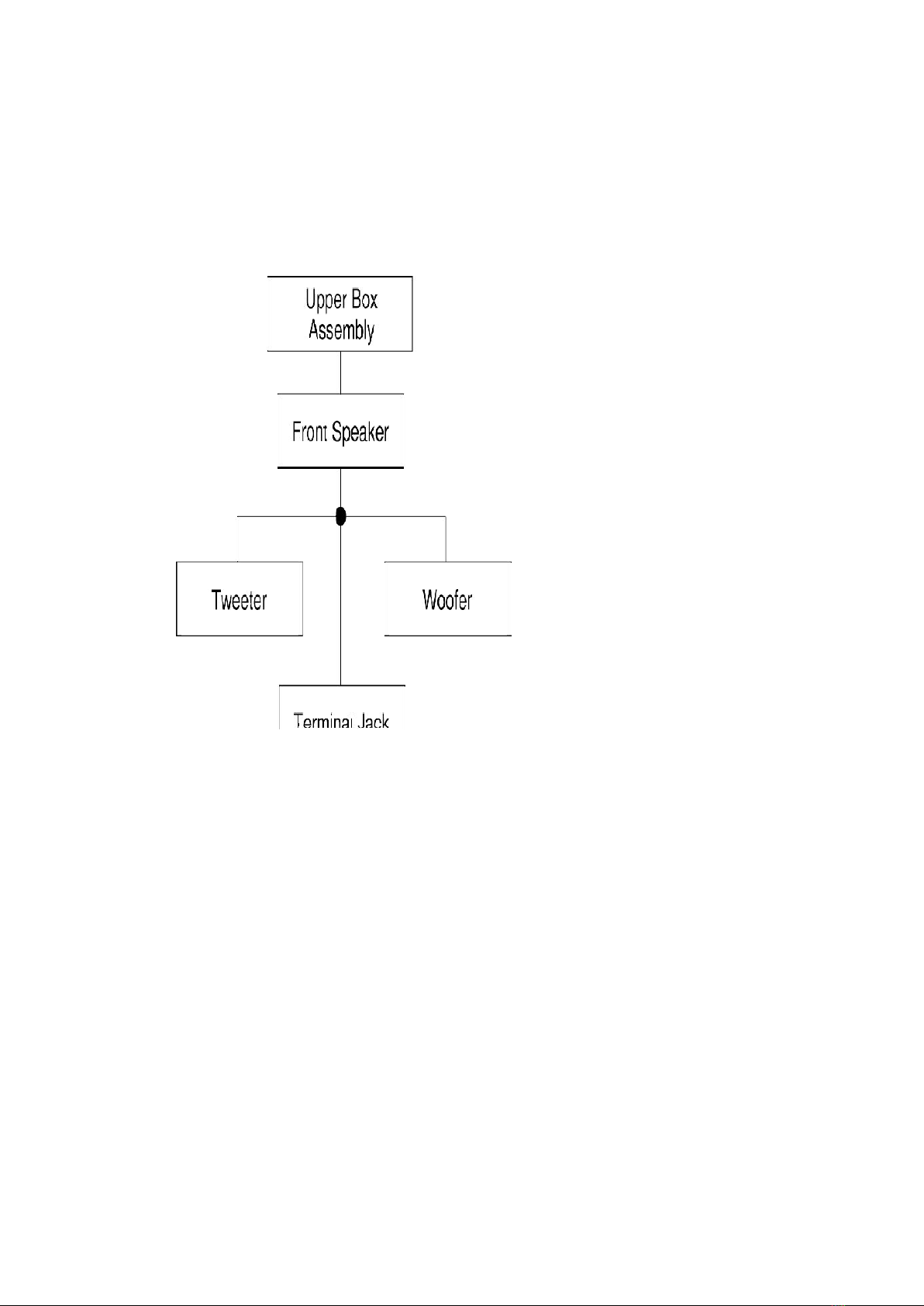
Type 2 way, 2 speaker system (Bass-ref.)
Speaker unit Impedance 4
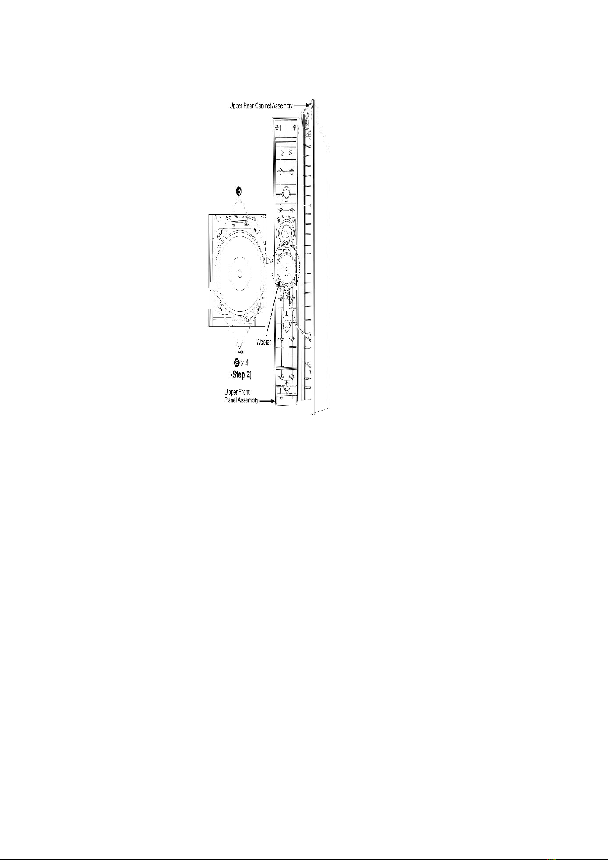
Woofer 6.5 cm (2-1/2”) Cone type
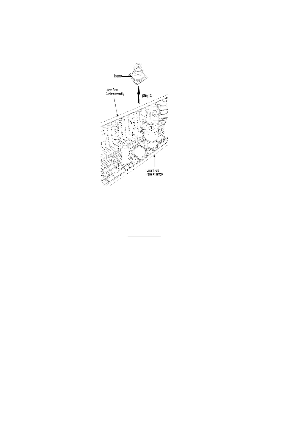
Tweeter 6 cm (2-3/8”) Cone type
Input power (IEC) 90 W* (Max)
Output sound pressure level 81 dB/W (1.0 m)
Cross over frequency 6 kHz
Frequency range 82 Hz - 41 kHz (-16 dB)
95 Hz - 40 kHz (-10 dB)
Dimensions (W x H x D) 252 mm x 1123 mm x 234 mm
9-29/32” x 44-7/32” x 9-7/32”
Mass 3.7 kg (8.2 lbs)
*Rating with low-cut filter equipped amplifier
Notes :
1. Specifications are subject to change without notice. / Mass and
dimensions are approximate.
2. Total harmonic distortion is measured by the digital spectrum
analyzer.
System : SC-HT740P-S Music Center : SA-HT740P-S
Front Speaker : SB-FS740P-S
Surround Speaker : SB-FS741P-S
Center Speaker : SB-PC740P-S
Subwoofer : SB-W740P-S
System : SC-HT740PC-S Music Center : SA-HT740PC-S
Front Speaker : SB-FS740P-S
Surround Speaker : SB-FS741P-S
Center Speaker : SB-PC740P-S
Subwoofer : SB-W740P-S
System : SC-HT740PX-S Music Center : SA-HT740PX-S
Front Speaker : SB-FS740P-S
Surround Speaker : SB-FS741P-S
Center Speaker : SB-PC740P-S
Subwoofer : SB-W740P-S
System : SC-
HT740GCPS
Music Center : SA-HT740GCPS
Front Speaker : SB-FS740P-S
Surround Speaker : SB-FS741P-S
Center Speaker : SB-PC740P-S
Subwoofer : SB-W740P-S
3

2005 Matsushita Electric Industrial Co. Ltd.. All rights reserved.
Unauthorized copying and distribution is a violation of law.
1. Assembling and Disassembling
“ATTENTION SERVICER”
Some chassis components may have sharp edges. Be careful when disassembling and servicing.
1. This section describes procedures for checking the operation of the
major printed circuit boards and replacing the main components.
2. For reassembly after operation checks or replacement, reverse the
respective procedures.
Special reassembly procedures are described only when required.
3. Select items from the following index when checks or replacement are
required.
4. Refer to the Parts No. on the page of “Parts Location and Replacement
Parts List” (Section 5), if necessary.
Below is the list of disassembly sections
- Disassembly of Upper Box Assembly
- Disassembly of Front Speaker
- Disassembly of Tweeter
- Disassembly of Woofer
- Disassembly of Terminal Jack
- Disassembly of Lower Box Assembly
- Disassembly of Lower Rear Cabinet Assembly
4

- Disassembly of Speaker Base Stand
1.1. Disassembly flow chart
The following chart is the procedure for disassembling the casing and inside parts for internal
inspection when carrying out the servicing.
To assemble the unit, reverse the steps shown in the chart as below.
1.2. Disassembly of Upper Box Assembly
5

Step 1: Remove the (+) white and (-) blue wires from the Upper Rear Cabinet Assembly.
Step 2: Pull out the Speaker Cable from the groove.
Step 3: Remove 1 screw from the Upper Rear Cabinet Assembly.
6

Step 4: Take out the Front Speaker Unit as arrow shown.
1.3. Disassembly of Front Speaker
Follow (step 1) to (step 4) in Item 1.2.
Step 1: Remove 10 screws from the Upper Rear Cabinet Assembly .
Step 2: Take out the Upper Rear Cabinet Assembly as arrow shown.
1.4. Disassembly of Tweeter
Follow (step 1) to (step 4) in Item 1.2.
Follow (step 1) to (step 2) in Item 1.3.
7

Step 1: Detach the (+) yellow and (-) black wires from the Tweeter.
Step 2: Remove 4 screws from the Tweeter.
8

Step 3: Remove Tweeter from the Upper Front Panel Assembly as arrow shown.
1.5. Disassembly of Woofer
Follow (step 1) to (step 4) in Item 1.2.
Follow (step 1) to (step 2) in Item 1.3.
9

Step 1: Detach the (+) red and (-) gray wires from the Woofer.
Step 2: Remove 4 screws from the Woofer.
Step 3: Take out the Woofer from the Upper Front Panel Assembly as arrow shown.
10

1.6. Disassembly of Terminal Jack
Follow (step 1) to (step 4) in Item 1.2.
Follow (step 1) to (step 2) in Item 1.3.
Step 1: Detach the (+) red and (-) gray wires from the Upper Rear Cabinet Assembly.
11

Step 2: Remove 1 screw from the Terminal Jack.
Step 3: Remove the Terminal Jack from the Upper Rear Cabinet Assembly.
1.7. Disassembly of Lower Box Assembly
Follow (step 1) to (step 4) in Item 1.2.
Step 1: Pull out the Speaker Cable from the ridges.
Step 2: Pull out the Speaker Cable from the inside groove by using hand.
12

Step 3: Remove 1 screw from the Lower Rear Cabinet Assembly.
Step 4: Remove 2 screws from the Base Stand Assembly.
Step 5: Pull out the Speaker Cable from the groove as arrow shown.
Step 6: Remove the Lower Box Assembly as arrow shown.
Step 7: Pull out the Speaker Cable from the Base Stand Assembly.
1.8. Disassembly of Lower Rear Cabinet Assembly
Follow (step 1) to (step 4) in Item 1.2.
13

Step 1: Remove 8 screws from the Lower Rear Cabinet Assembly.
Step 2: Take out the Lower Rear Cabinet Assembly from the Lower Front Panel Assembly.
1.9. Disassembly of Base Stand Assembly
Follow (step 1) to (step 4) in Item 1.2.
Follow (step 1) to (step 7) in Item 1.7.
14

2. Connection of the Speaker Cables
- Be sure to connect speaker cables before connecting the AC power
supply cord.
- The load impedance of any speaker used with this unit must be 4 .
- Be sure to connect the cable from the right speaker to the right terminal
and the cable from the left speaker to the left terminal.
1. Strip off the outer covering, and twist the center conductor. Make sure
the bare ends of the wires are not unravelled. (If they are, twist them
tight again.)
2. Insert the wire to the rear panel of the unit and close the lever.
Notes :
15

- To prevent damage to circuitry, never short-circuit positive (+) and
negative (-) speaker wires.
- Be sure to connect only positive (white) wires to positive (+) terminals
and negative (blue) wires to negative (-) terminals.
Incorrect connection can damage the speakers.
Positioning the speakers
How you set up your speakers can affect the bass and the sound field.
Note the following points:
- Place the speakers on flat secure bases.
- Placing speakers too close to floors, walls, and corners can result in
excessive bass. Cover walls and windows with a thick curtains.
- Left and right speakers are interchangeable, but front and surround
speakers are not.
Setup example
Place the front, center and surround speakers at approximately the same distance from the seating
position.
The angles in the diagram are approximate.
Used only supplied speakers
- Using other speakers can damage the unit, and sound quality will be
negatively affected.
- Set the speakers up on an even surface to prevent them from falling.
Take care proper precautions to prevent the speakers from falling if you
cannot see them up on an even surface.
Main unit
Note
- Keep your speakers at least 10 mm (13/32”) away from the system for
16

proper ventilation.
- To allow for proper ventilation and to maintain good airflow around the
main unit, position it with at least 5 cm (2”) of space on all sides.
- Do not block the ventilation holes of the main unit.
Center speaker
- Vibration caused by the center speaker can disrupt the picture if it is
placed directly on the television. Put the center speaker on a rack or
shelf.
- To prevent the speakers from falling, do not place directly on top of the
television.
Subwoofer
Place to the right or left of the television, on the floor or a sturdy shelf so that it will not cause vibration.
Leave about 30 cm (11-13/15”) from the television.
Caution
- Do not stand on base.
Be cautious when children are near.
e.g. Front speaker
- Do not touch the netted area of the speakers.
e.g. Surround speaker
Notes on speaker use
- You can damage your speakers and shorten their useful life if you play
sound at high levels over extended periods.
17

- Reduce the volume in the following cases to avoid damage.
- When playing distorted sound.
- When the speakers are reverberating due to a record player, noise from
FM broadcasts, or continuous signals from an oscillator, test disc, or
electronic instrument.
- When adjusting the sound quality.
- When turning the unit on or off.
3. Connection of Wiring Diagram
4. Exploded view
4.1. Cabinet Parts Location
18

19

4.2. Packaging
Note: The diagram below shows the packaging for SB-HT740P-S.
Pls also refer to Service Manual of SB-FS741P-S (MD0512486C0) for packaging.
20
Table of contents
Other Matsushita Electric Speakers manuals