Item FL Display Key Operation
Mode Name Description Remote Control Key
Initialization Initialization.
User settings are
cancelled and player is
initialized to factory
setting.
In STOP (no disc) mode,
STOP button on the player,
button on the
remote control unit.
DVD Module
Reset
To reset DVD Module. In initialisation, press and
STOP button on the player
followed by “Enter” button
the remote control.
Cancelled automatically 5
seconds later.
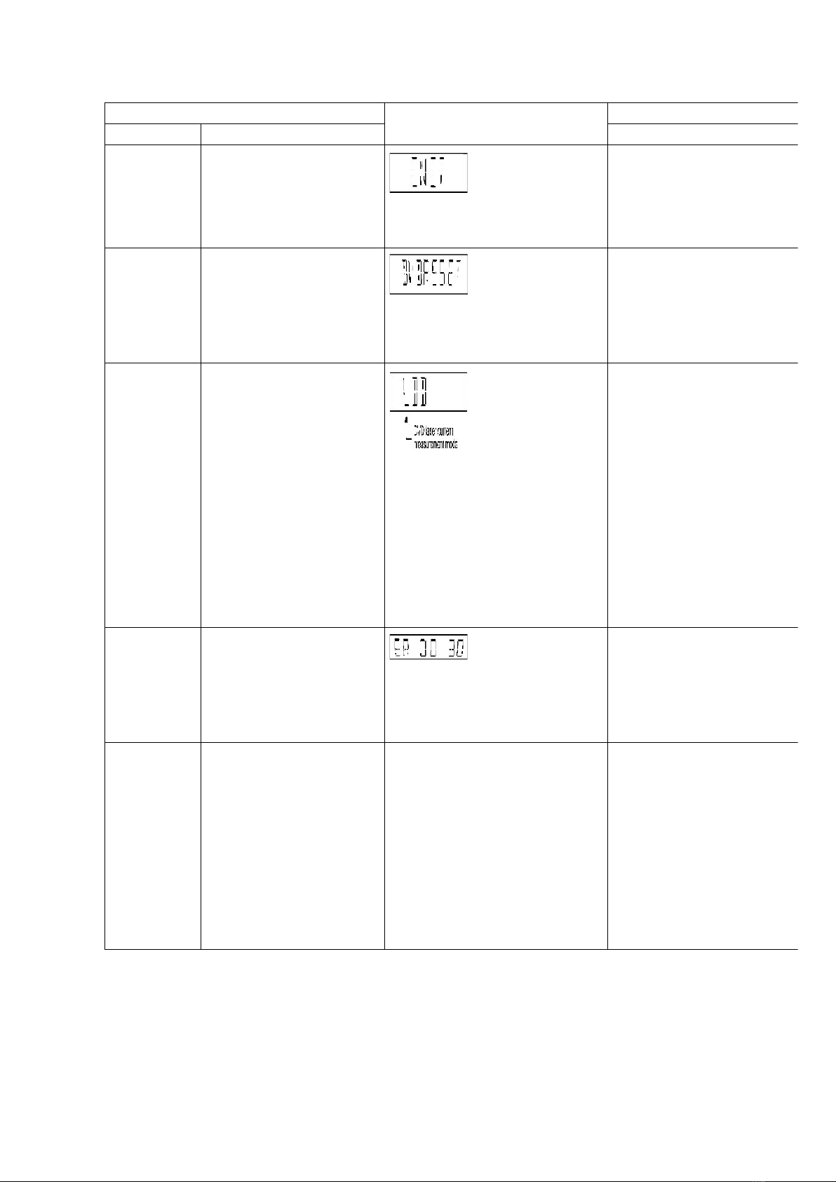
DVD laser
drive current
measurement
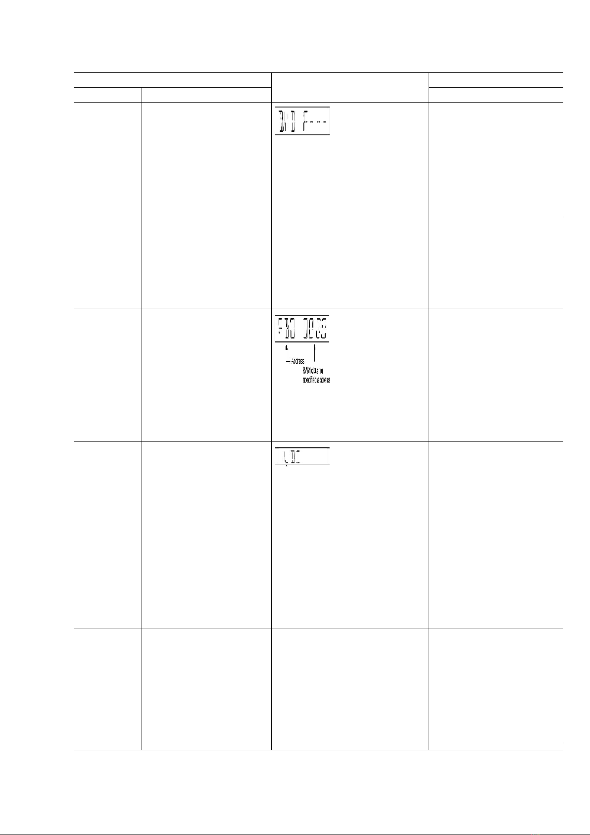
DVD laser drive current
measurement.
DVD laser drive current is
measured and the result is
displayed together with
the initial value stored in
the EEPROM IC.
After the measurement,
DVD laser emission is kept
on. It is turned off when
POWER key is switched
off. (It is also turned off
when POWER button on
the player is switched off.)
The value denotes the current in
decimal notation.
The above example shows the
initial current is 20mA and the
measured value is 20mA.
In STOP (no disc) mode,
STOP button on the player,
FUNCTIONS button on the
remote control unit.
Cancelled automatically 5
seconds later.
Press “FL Display” button
remote control unit for next
page (FL Display) on values
DVD drive current.
Communic-
ation error
display
Displays frequency of
communication errors
between system control IC
and mechanism control IC
during DVD module.
In STOP (no disc) mode,
STOP button on the player,
“MENU” button on the
control unit.
Cancelled automatically 5
seconds later.
Initial setting
of laser drive
current
Initial setting of laser drive
current.
Initial current value for
each of DVD laser and CD
laser is separately saved
in the EEPROM IC. The value denotes the current in
decimal notation. The above
example shows the initial
current 20mA and 23mA for DVD
laser and CD laser respectively
when the laser is switched on.
In STOP (no disc) mode,
STOP button on the player,
PAUSE button on the
control unit.
Cancelled automatically 5
seconds later.
Press “FL Display” button
remote control unit for next
page (FL Display) on values
laser drive current.
5