5
HCD-NEZ31
SECTION 2
GENERAL This section is extracted from
instruction manual.
Basic Operations
Before using the system
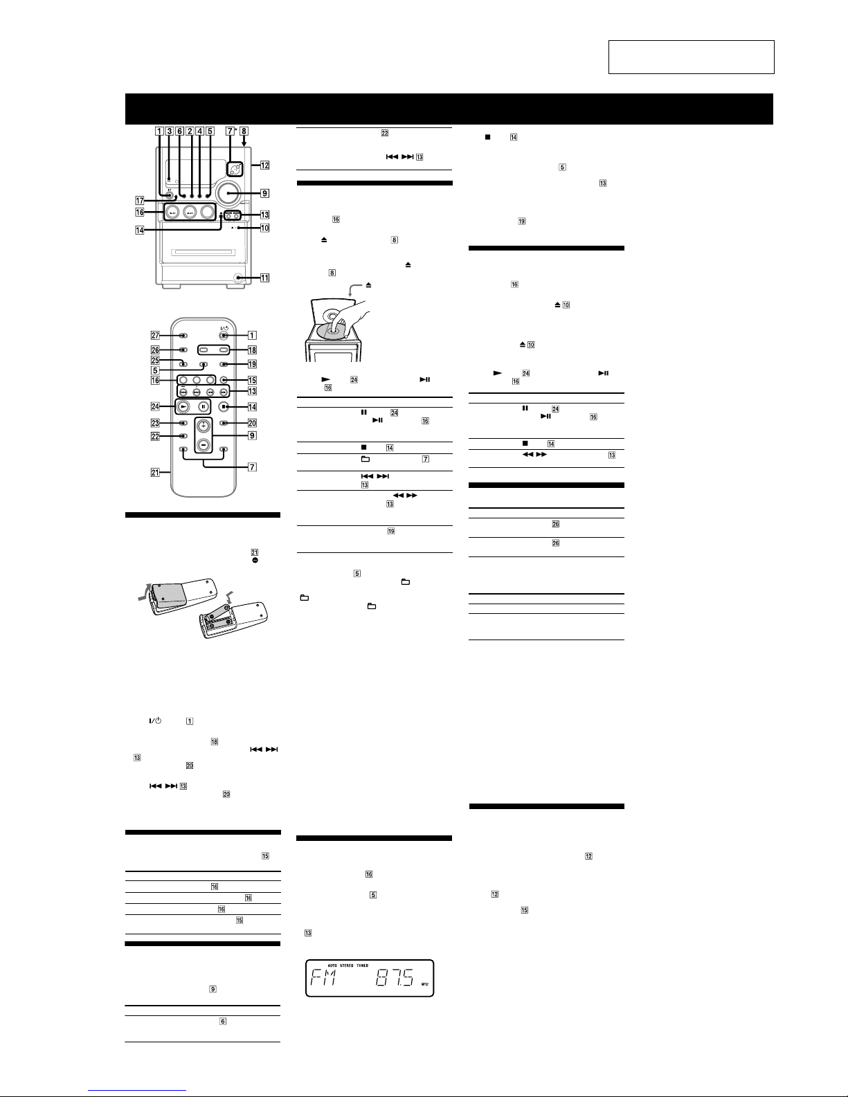
To use the remote
Slide and remove the battery compartment lid , and
insert the two supplied R6 (size AA) batteries, side
first, matching the polarities shown below.
Notes on using the remote
• With normal use, the batteries should last for about six months.
• Do not mix an old battery with a new one or mix different types of
batteries.
• If you do not use the remote for a long period of time, remove the
batteries to avoid damage from battery leakage and corrosion.
To set the clock
1
Turn on the system.
Press (power) .
2
Select the clock set mode.
Press CLOCK/TIMER SET on the remote. If the
current mode appears on the display, press /
on the remote repeatedly to select “CLOCK” and
then press ENTER on the remote.
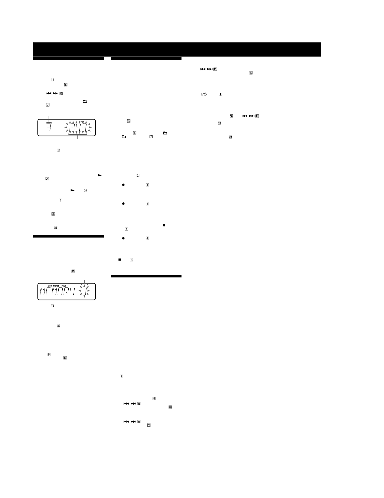
3
Set the time.
Press / on the remote repeatedly to set
the hour, and then press ENTER on the remote.
Use the same procedure to set the minute.
The clock settings are lost when you disconnect the
power cord or if a power failure occurs.
Playing a CD/MP3 disc
1
Select the CD function.
Press CD on the remote.
2
Place a disc.
Press PUSH OPEN/CLOSE on the unit,
and place a disc with the label side up on the CD
compartment.
To close the CD compartment, press PUSH OPEN/
CLOSE on the unit.
PUSH OPEN/CLOSE
3
Start playback.
Press (play) on the remote (or CD/ (play/
pause) on the unit).
To Press
Pause playback (pause) on the remote (or
CD/ (play/pause) on the
unit). To resume play, press the
button again.
Stop playback (stop) .
Select a folder on an
MP3 disc
+/– (select folder) .
Select a track or file / (go back/go forward)
.
Find a point in a
track or file
Hold down / (rewind/fast
forward) during playback,
and release the button at the
desired point.
Select Repeat Play REPEAT on the remote
repeatedly until “REPEAT” or
“REPEAT 1” appears.
To change the play mode
Press PLAY MODE repeatedly while the player is
stopped. You can select normal play (“ ” for all MP3
files in the folder on the disc), shuffle play (“SHUF” or
“SHUF*”), or program play (“PGM”).
* When playing a CD-DA disc,
(
SHUF) Play performs the same
operation as normal (SHUF) Play.
Notes on Repeat Play
• All tracks or files on a disc are played repeatedly up to five times.
• “REPEAT 1” indicates that a single track or file is repeated until you
stop it.
Notes on playing MP3 discs
• Do not save other types of files or unnecessary folders on a disc that
has MP3 files.
• Folders that have no MP3 files are skipped.
• MP3 files are played back in the order that they are recorded onto
the disc.
• The system can only play MP3 files that have a file extension of
“.MP3.”
• If there are files on the disc that have the “.MP3” file extension,
but that are not MP3 files, the unit may produce noise or may
malfunction.
• The maximum number of:
– folders is 150 (including the root folder).
– MP3 files is 255.
–
MP3 files and folders that can be contained on a single disc is 256.
– folder levels (the tree structure of files) is 8.
• Compatibility with all MP3 encoding/writing software, recording
device, and recording media cannot be guaranteed. Incompatible
MP3 discs may produce noise or interrupted audio or may not play
at all.
To stop automatic scanning
Press (stop) .
To tune in a station with a weak signal
If “TUNED” does not appear and the scanning does
not stop, press TUNING MODE repeatedly until
“AUTO” and “PRESET” disappear, and then press
+/– on the remote (or TUNING +/– on the unit)
repeatedly to tune in the desired station.
To reduce static noise on a weak FM stereo
station
Press FM MODE on the remote repeatedly until
“STEREO” disappears to turn off stereo reception.
Playing a tape
1
Select the tape function.
Press TAPE on the remote.
2
Insert a tape.
Press PUSH OPEN/CLOSE on the unit, and
insert the TYPE I (normal) tape into the cassette
holder with the side you want to play facing forward.
Make sure there is no slack in the tape to avoid
damaging the tape or the tape deck. Press PUSH
OPEN/CLOSE on the unit again to close the
cassette holder.
3
Start playback.
Press (play) on the remote (or TAPE/
(play/pause) on the unit).
To Press
Pause playback (pause) on the remote (or
TAPE/ (play/pause) on the
unit). To resume play, press the
button again.
Stop playback (stop) .
Rewind or fast
forward
/(rewind/fast forward) .
Changing the display
To change Press
Information on
the display*
DISPLAY on the remote
repeatedly when the system is on.
Display mode
(See below.)
DISPLAY on the remote
repeatedly when the system is off.
* For example, you can view CD/MP3 disc information, such as the
track or file number or folder name during normal play, or the total
play time while the player is stopped.
The system offers the following display modes.
Display mode When the system is off,
1)
Clock The clock is displayed.
Power Saving
Mode
2)
The display is turned off to conserve
power. The timer and clock continue
to operate.
1)
The STANDBY indicator lights up when the system is off.
2)
When the system is in Power Saving Mode, the following functions
are unavailable:
– setting the clock.
– changing the AM tuning interval
– changing the CD power manage function
Notes on the display information
• The following are not displayed;
– total playing time for a CD-DA disc depending on the play mode.
– total playing time for an MP3 disc.
– remaining playing time for an MP3 file.
• The following are not displayed correctly;
– elapsed playing time of an MP3 file encoded using a VBR
(variable bit rate).
– folder and file names that do not follow either the ISO9660 Level
1, Level 2 or Joliet in the expansion format.
• The following are displayed;
– ID3 tag information for MP3 files when ID3 version 1 and version
2 tags are used.
– up to 30 characters of ID3 tag information using uppercase letters
(A to Z), numbers (0 to 9), and symbols (" $ % ’ ( ) * + , – . / < =
> @ [ \ ] _ ` { | }).
Selecting a music source
Press the following buttons (or press FUNCTION
repeatedly).
To select Press
CD CD on the remote.
Tuner TUNER/BAND .
Tape TAPE on the remote.
Component (connected
using an audio cord)
FUNCTION repeatedly
until “AUDIO IN” appears.
Adjusting the sound
To adjust the volume
Press VOLUME +/– on the remote (or turn the
VOLUME control on the unit) .
Notes on playing multisession discs
• If the disc begins with a CD-DA (or MP3) session, it is recognized
as a CD-DA (or MP3) disc, and playback continues until another
session is encountered.
• A disc with a mixed CD format is recognized as a CD-DA (audio)
disc.
Listening to the radio
1
Select “FM” or “AM.”
Press TUNER/BAND repeatedly.
2
Select the tuning mode.
Press TUNING MODE repeatedly until “AUTO”
appears.
To add a sound effect
To Press
Generate a more dynamic
sound (Dynamic Sound
Generator X-tra)
DSGX on the unit.
3
Tune in the desired station.
Press +/– on the remote (or TUNING +/– on the unit)
. Scanning stops automatically when a station is
tuned in, and then “TUNED” and “STEREO” (for
stereo programs) appear.
Using optional audio
components
To connect an optional headphones
Connect headphones to the PHONES jack on the
unit.
To connect an optional component
Connect additional audio component to the AUDIO
IN jack on the unit using an audio analog cord (not
supplied). Turn down the volume on the system, and then
press FUNCTION repeatedly to select the AUDIO IN
function.
Set the sound effect EQ on the remote
repeatedly to select “BASS”
or “TREBLE,” and then
press /
repeatedly to adjust the level.