Mattson SQ816 User manual

1

2
Table o’ Contents
Welcome .........................................................................................................................3
Unpacking, Power Requirements, and Power Up Procedure .........................................4
SQ816 Panel Layout .......................................................................................................5
Definitions .......................................................................................................................6
Timing Section.................................................................................................................8
Stage Control Section ...................................................................................................10
Stage Matrix .................................................................................................................11
Response Control Section ............................................................................................13
Output Section...............................................................................................................14
Interface Section ...........................................................................................................16
User-Programmable Functions .....................................................................................17
Adjustments and Trim Procedures ...............................................................................22
Ver 1.27 2013-02-01

3
Welcome
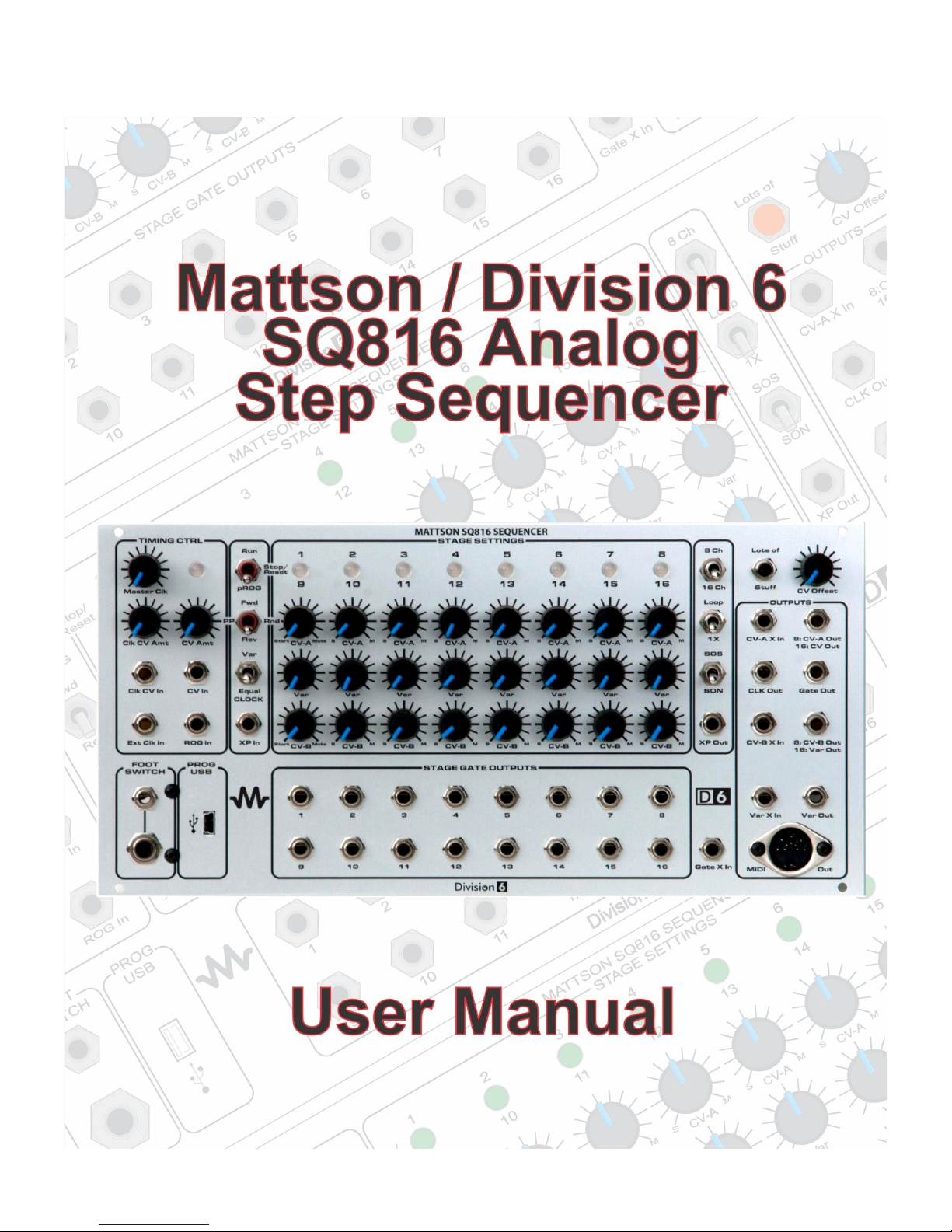
Thank you for becoming the proud owner of one of the most exciting new products to come from the
combined laboratories of Mattson Mini Modular and Division 6: The SQ816 Analog Step Sequencer.
The SQ816 sequencer is a joint project between Mattson Mini Modular and Division 6 that has been in
development for more than a year. And what a sequencer it has become!
There are two formats - each is available from either the Division 6 or the Mattson Mini Modular web sites,
or from select dealers.
Division 6: http://division-6.com/shop/Synthesizers/
MMM: http://www.mattsonminimodular.com/shop/index.php?main_page=index&cPath=5_10
The Mattson Mini Modular format is comprised of two separate modules. The main SQ816 sequencer
module is a 3-wide Mattson format module and the Expansion module is a 2-wide Mattson format module.
The Division 6 SQ816 sequencer module combines both the Main SQ816 sequencer and Expansion
modules into one 52HP (10-3/8”W) Eurorack format module.
I have over 30 years of synthesizer history starting with the invention and production of the first actively
portable self-contained synthesizer, which I named the Syntar in 1978. It was innovative for its time and
was the first “keytar” produced. I use the term “Keytar” in its commonly utilized generic term.
I’ve been playing with analog step sequencers for 30 plus years, and decided to produce a system that had
all of the features I enjoyed, the features I always wished they had, and designed out the stuff I didn’t like. I
also added a few extra things just because I could, and because I thought they were awesome features to
try! The SQ816 is the result of that determination.
I designed the hardware and incorporated the help of Division 6 to write and implement the software to
create a truly amazing step sequencer.
The SQ816 is designed to be primarily utilized as a CV/Gate controller. There are numerous inputs and
outputs to help facilitate stand-alone operation with virtually any analog CV/Gate synthesizer system and
expansion interfaces to allow the operation of multiple SQ816 sequencers in series or parallel.
This manual has several parts. There is a Definitions section to help you understand the terminology utilized
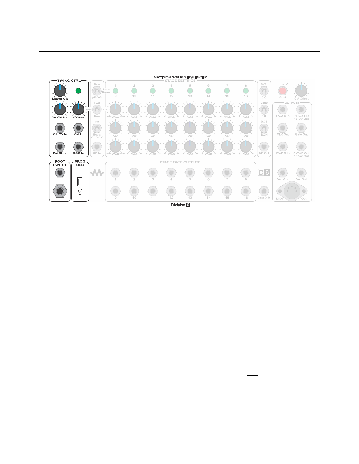
within the text of this manual, a Panel Layout section which explains the primary panel control and I/O
functions, dedicated sections for each of the major function blocks on the SQ816, and a programming
section which explains the multitude of user-programmable features.
A Calibration section is also provided to allow you to tweak some of the functions to suit your preference or
“dial in” some parameters to match outboard system responses. The calibrations detailed allow the user to
change LED brightness, adjust the upper and lower ranges of the internal VC clock, and tweak in all of the
1Volt / Octave input and output functions.
We will be developing short videos that highlight specific functions and show a few hints and tips. This will
be an ongoing project and will be available for viewing on my YouTube channel. My user name on YouTube
is MMModsynth, so check it often for new videos.
Software updates via USB will be available on the SQ816 page on the Mattson Mini Modular WIKI site and
on the Division 6 web site when they are available.
Thank you again. We’ve had a lot of fun developing this product, and we’re looking forward to seeing the
creativity from our customers utilizing this module.
George Mattson

4
Unpacking, Power Requirements, and Power Up Sequence
What’s in the box? When you open the packaging for your SQ816 sequencer, you’ll find:
The SQ816 sequencer
Programming Quick Reference card
Jacklight
Power cable
USB cable
Mounting screws (4)
Power requirements: The Mattson/ Division 6 sequencer was designed to operate from either the standard
Eurorack power standard of +/- 12VDC or the +/- 15VDC power found on many other synthesizer systems.
The +V line draws 86mA, while the –V line draws 32mA.
The SQ816 has a 10 pin dual row keyed power header and a 6 pin MTA header on the main board. Either
connector can be used to power the system.
The supplied power cable has a 10 pin keyed socket on one end of the ribbon cable and a 16 pin keyed
socket on the other end. The 10 pin socket connects to the 10 pin keyed header on the lower-right of the
SQ816 sequencer main board (when viewed from the rear). The “stripe” on the ribbon cable is oriented to
be located toward the bottom of the circuit board. Since the supplied power cable is keyed, you can’t plug it
in backward. If you use a different power cable that isn’t keyed and connect it backward, no problem - the
SQ816 automatically orients the power to the proper polarity. Connect the keyed 16 pin socket on the other
end of the ribbon cable to your system power bus. If your power distribution headers aren’t keyed, verify the
stripe location prior to connecting. The stripe indicates the negative voltage (V-).
The SQ816 sequencer clock is calibrated for the power scheme utilized based on the format provided. The
only effect of using a higher or lower voltage power supply is that; the lower the power supply voltage, the
faster the VC clock will cycle and it will need to have the range adjusted. Refer to the Adjustments and Trim
Procedures section at the end of this manual for further information.
Power up sequence: On initial power up, the SQ816 will initially perform an LED check by producing three
scans across the Stage Status LEDs. On the first scan, the LEDs will light red. On the second scan, the
LEDs will light yellow, and on the third scan the LEDs will light green. On each scan, the clock LED will be lit
continuously at the current scan color.
After the LED check, The LEDs will go dark and then display the software version number. The stage
number of the LED will indicate the numeric value (1-8), and the clock LED is utilized to indicate the
numeral 0 (zero). The first LED indicates the integer portion of the version number. The second LED
indicates the first decimal number. The third LED indicates the second decimal number.
The SQ816 sequencer will enter ready mode (no stages lit, clock LED flashing) after the Version Number
display
We’ve also created a short video to illustrate the power up routine:
www.youtube.com/watch?v=jns2ajQR1JE

5
SQ816 Panel Layout

6
Definitions
Ready or “Stand by”: Clock running, no stages active. Clock Indicator LED flashing red at clock rate
(indicating Gate Mute)
CV: Control Voltage. A voltage used to change an operational parameter. Usually between +/- 15VDC.
VC: Voltage Controlled. A functional parameter that can be altered by applying a Control Voltage.
1V/Oct: One Volt per Octave. A “standard” where each volt applied will cause an operational change of one
octave on pitch related devices.
Gate: A voltage change used for initiating a specific event. Usually going from 0V to either +5V or +15V
Stage Gate: A gate generated from the activation of a specific stage event. The SQ816 stage gates
produce a +5V gate pulse.
“Start” or “Beginning”: The beginning of a sequence. Stage 1 in Forward mode. Stage 8 in Reverse / 8
channel mode. Stage 16 in Reverse / 16 channel mode.
Start Zone: A region in the lowest CCW position of the CV-A and/or CV-B controls.
In pROGram mode, the active stage LED will flash when the region is active
In Run mode, the sequence will progress to the stage prior to the stage set as “Start”, and
then return to the beginning when the sequence is started.
In Loop mode, the beginning is the first stage of a local sequence.
In 1X mode, the beginning is assumed to be off system. The sequence will truncate,
generate an XP out pulse and enter Ready Mode.
Last stage: The last stage of a programmed sequence before repeating, changing direction, or going into
Ready Mode.
ROG: Run-On-Gate. A sub function of pROG mode where stage advances occur only when a gate is
applied to the ROG input.
PIG: Pause-Including-Gate. A Run mode operation where a gate applied to the ROG input will stop stage
advances until the Gate is released. The main gate continues to be generated at the clock rate.
SOS: Start-On-Stage. A start operation where starting the stage advancement will play the current stage
first before advancing.
SON: Start-On-Next. A start operation where starting the stage advancement will play the next stage first
before advancing.
Loop/1X: Control for determining if a sequence repeats, or makes one pass and enters Ready mode.
Var: Variable. A control voltage generated by the Var settings. Primarily utilized to vary the clock rate on a
per stage basis.
XP: eXPansion. Used for off-module interfacing and timing.

7
Definitions (continued)
Zoned Mute: Two regions in the upper CW position of the CV-A and CV-B controls for determining if the
Main Gate or Main Gate and Stage Gate are suppressed for a specific stage. During a stage specific mute,
the previous valid generated CV if held during the muted stage.
X in: eXternal Input. Used for interfacing and summing external CVs to the function specific output.
Local: Refers to on-system operations.
Global: Pertaining to all stages, or a bank of stages during an operation. Usually selected by programming
in Ready mode.
Clock: Timing device for determining the stage advance rate. An external clock applied to the Ext Clk input
interrupts and replaces the internal VC clock. The Tap Tempo feature interrupts and replaces the internal
VC clock or the external clock.
Quantize / Linear: Linear mode allows for a continuous sweep from 0-3 Volts using the control knob for a
stage. No MIDI data is output for a bank in Linear mode. In Quantize mode, the full CV range is stepped in
semitone values in the 12 semitone/octave western scale. MIDI note data output is enabled for a bank set
to Quantize mode.
Bus: Also called a bank. The output signal from a specific row of stage settings.

8
Timing Section
The Timing Section sets stage advance timing and contains the LED Clock Indicator
Master Clk: Rate control for internal clock. Using the Master Clock panel control, the minimum rate is about
10 seconds per stage and the maximum rate is about 100 Hz. Both limits can be affected by a control
voltage applied to the Clk CV In jack and adjusted with the Clk CV Amt control. With a negative CV
applied, the minimum rate is about 1.5 hours per stage. With a positive CV, the maximum rate tops out at
about 133 Hz before the LEDs and gate start cutting out, but that can be fun too.
LED Clock Indicator: The Clock Indicator LED flashes to indicate the frequency of the internal clock
oscillator. The clock LED is also used to confirm that a user function has been programmed, and the LED
color will indicate one of the following
Green: Internal VC Clock or external clock at the Ext Clk In jack is in control of the stage advance
timing. The LED flashes at stage advance clock rate.
Yellow: Indicates user programmed Tap-Tempo control of the stage advance. VC internal and
external clocks are disabled.
Red: Indicates that the main gate output is disabled (muted) either from a stage setting or manually
invoked.
Clk CV Amt: Clock Control Voltage Amount. Adjusts the amount of modulation from the Clk CV In jack.
Clk CV In: Control Voltage input for modulating the rate of the internal clock. See Master Clk for more
details.
CV Amt: Used for adjusting the amount of voltage change applied to the Bus A and Bus B outputs from the
CV In jack (Fully CCW = no change, Fully CW is about 1V/Octave).
CV In: Used for applying an external CV to both Bus A and Bus B outputs. This is an analog input, and will
not affect MIDI out pitch.
Ext Clk In: External Clock Input.

9
Timing Section (continued)
ROG In: Run On Gate Input. See the User-Programmable Functions section for more detail on the ROG
Input.
Footswitch: An input jack for a normally-open shorting type footswitch. It performs the same function as the
pushbutton. See the User-Programmable Functions section for more detail on using the Footswitch input.
USB: See the Interface Section for more details.

10
Stage Control Section
The Stage control section includes operational settings for programming, stopping and running the
sequencer. Included are stage advance controls for setting forward, reverse, or ping pong operation. In
addition, the duration of each stage can be set to be constant, or determined by the internal VC Clock under
control of the VAR knob settings.
Run/Stop-Reset/pROG switch: The main user control for starting, stopping, or programming the
sequencer. The switch position is also used for selecting specific user program functions.
Run: Normal operational for stage advance at the controlling clock rate.
Stop-Reset: Halts stage advance operation. First button press resets to beginning stage.
Subsequent button presses program Tap-Tempo rate.
pROG: Stage pROGramming mode. Stage selection advances with each button press. The Gate is
activated to assist with settings. The (ROG) position is also for program selection and utilizing ROG
mode.
Fwd/PP-Rnd/Rev switch: Main directional control The switch position is also used as a bank pointer during
specific user program functions. Note: If the SON/SOS switch is in the SOS position, the sequence will
double hit the beginning and endpoints of the sequence while in Ping-Pong mode.
Fwd: Active stage advances in increasing stage numbers.
PP-Rnd: Active stage advances from beginning to last stage and reverses direction. Rnd = Random
stage number generation. Invoked by pressing the push button momentarily while running.
Rev: Active stage advances in retrograde in decreasing stage numbers.
Var/Equal switch: Allows for selecting equal tempered stage advance timing or variable stage length
timing.
Var: Var row stage setting controls the VC clock rate for a specific stage.
Equal: Clock rate is equal tempered and not affected by the Var row stage settings.
XP In: See Interface Section for more details.

11
Stage Matrix
The Stage Matrix includes the controls for setting the values of each row for each stage and LEDs for
indicating stage status. The stage controls are in a matrix of three rows and eight columns with a status
LED above each column.
Stage LED: Provides a visual indication of the stage status. In pROGram mode, the LED flashes if the
stage CV control is in the start zone (CCW). It also flashes red for main gate mute and is solid red for main
and stage gate mute selection.(CW)
Off: Stage column is inactive.
Green: Stages 1-8 are active, depending on which stage is lit. CV-A is applied to the CV-A output.
Yellow: (in 16 channel mode) Stages 9-16 are active, CV-B setting is applied to the CV-A output.
Red: The Main Gate and/or the Stage Gate is not generated for that stage. Effectively used for a
stage mute.
CV A row: Used for selecting stage CV output, start point or, main gate and stage gate mute. Row A is
active during stage 1-8 operation.
Fully CCW to slightly CW sets the Start Stage. The Status LED will flash at the clock rate
Fully CW to slightly CCW sets the Mute Stage. The Status LED will be red. Flashing red (Zone 1)
means that the Main Gate will not be generated for that stage, although the Stage Gate will still be
active. Solid red (Zone 2) means that both the Main Gate and Stage Gate will not be generated for
that stage.
Between the Start and Mute Zones, the CV control provides a 0-3V (three octave) CV to the CV-A
output.

12
Stage Matrix (continued)
Var row: Used for selecting a CV output for the active stage. CV output range is approximately 0 to 3 Volts.
The direct CV is available at the Var Out jack. If the Var/Equal switch is in the Var position, this CV setting
is applied to the VC Clock timing. During 16 channel operations, this CV is routed to the CV-B output.
CV B row: Used for selecting stage CV output, Start Point, or Main Gate and Stage Gate mutes. During 8
channel operation, this CV is applied to the CV-B output, and Zone Position controls for Row B are
disabled. This acts as a 2 x 8 step sequence where Row CV-A controls the CV-A output, and Row B
controls the CV-B output. During 16 channel operations, the CV-B row controls stages 9-16 and the CV
output is routed to the CV-A output. Think of this as a 1 x 16 step sequence, with the CV for all 16 stages
going to the CV-A output. The zone position controls for Row B are enabled and the Stage LED will light
yellow to indicate the CV-B row is active.
Stage Gates: Individual gate outputs for each stage. A +5V gate output mapped to specific active stage.
The Stage Gate is active for a stage set to Zone 1 Mute. The Stage Gate is inactive for a stage set to Zone
2 Mute. The Gate length is set by the Main Gate Length program setting. Default = ”Follow.” See the User-
Programmable Functions section for more information.

13
Response Control Section
The Response Control Section includes controls for setting operational parameters.
8/16 select switch: Sets the mode to 8 channel or 16 channel operation. Also used when toggled back and
forth within one second to invoke user programs.
Loop/1X select switch: Determines if the sequencer will advance to the end in one pass or loop
continuously. Also used when toggled back and forth within one second to invoke user programs. (Consider
Loop as being primarily for local operations and 1X for basic system interface with other systems.) …But,
that’s just a general consideration…
1X mode: Sequencer will advance to the last stage and enter ready “stand by” mode until reset. In
the 1X mode, an XP Out pulse is generated at the last stage +1 clock cycle.
Loop mode: The sequence will restart to the beginning after the last stage is reached. No XP out
pulse is generated in loop operations.
SOS/SON select switch: Control for determining how the sequencer starts. Also used when toggled back
and forth within one second to invoke user programs.
SOS: Start-On-Stage. When the sequencer stage advance is invoked, the current stage is played
before advancing. In Ping-Pong operation, the sequence will play the beginning and the end stage
of the sequence twice. Think of the operation as playing all sequence stages then, starting over the
other direction.
SON: Start-On-Next (stage). Typical sequencer start. When the sequencer stage advance is
invoked, the next stage is played first.
XP Out jack: eXPansion out. See the Interface Section for more details.

14
Output Section
The Output Section includes the outputs and controls for the CV channels, the Gate and Clock outputs, and
interfacing.
“Lots of Stuff” pushbutton: Primary user input switch based on current mode.
In pROG mode, advances the stage once per button press, it generates one clock pulse per press. If held in
pROG mode continuously for over three seconds, the stages will advance at the clock rate until released. In
Stop mode, the first button press sets the active stage to the Start stage. Subsequent button presses in
Stop mode will program Tap Tempo mode (average of last 5 button presses). If inadvertently stuck in Tap
Tempo mode, hold pushbutton for ~5 seconds to exit. The Clock LED will switch from yellow to green or red
if mute is active. Holding the button for more than 10 seconds will initiate a soft reboot.
In Run mode, pressing the push button will mute the Main Gate output. The clock LED will be red.
Pushbutton mutes will not hold the last valid stage value at the CV output. In PP-Rnd mode (Ping Pong-
Random), each button press toggles between Ping Pong and Random stage generation.
When returning to Ping Pong from Random, the sequence will start on the stage and direction it was on
when Random was invoked. When switching between Ping Pong and Random, holding the Pushbutton will
invoke the gate mute after the mode change after one-half of a clock cycle.
CV Offset: Analog control that applies 0 to approximately 1.1V (a little over an octave) for tuning both CV
outputs. This control will not affect the MIDI note tuning.
CV-A X In: An external VC input applied to the CV A output. Primarily used for multiple system interfacing.
CV-A Out: The main CV output. Channels 1-8 in 8 channel mode. Channels 1-16 (CV A and CV B rows) in
16 channel mode.
Clock Out: Direct clock output available for interfacing. In Run Mode, the clock output is available. In pROG
Mode, the Clock Out jack outputs one clock pulse for every pushbutton press.

15
Output Section (continued)
Gate Out: Main gate output typically applied to an Envelope Generator. Programmable for Short, Follow
(clock cycle) and Long. See the Gate Length feature in the User-Programmable Functions section for more
details.
CV-B X In: An external VC input that is applied to the CV-B output. Primarily used for multiple system
interfacing.
CV-B Out: Secondary CV output. CV-B row available during 8 channel operation. Var row available during
16 channel operation.
Var X In: An external VC input that is applied to the Var output. Primarily used for multiple system
interfacing.
Var Out: Raw CV output from the Var row knob settings.
Gate X In: Used for daisy chaining external gates for multi-system operation. It is applied to the Gate out.
MIDI Out: Two channel MIDI output providing note value, note on and note off MIDI data for each output
bank. The MIDI output provides MIDI note values based on the active stage setting. The note values are
not affected by any of the CV inputs (CV-A X In, CV-B X In, CV In, CV Amt, CV Offset, VAR X In). The MIDI
values are generated based on the CV-A and CV-B output bus active in 8 or 16 channel mode. In 8 channel
mode, the MIDI is generated based on the CV-A setting for one note and CV-B for the second note. In 16
channel mode, CV-A + CV-B from the CV-A bus generates the first MIDI note, The Var settings from the
CV-B bus generates the second MIDI note. Note length is determined by the user main Gate Length
program setting. Default = ”Follow”)
The default MIDI channel is channel 1 for both CV-A and CV-B outputs. Each CV bus can be programmed
to any MIDI channel 1-16 or, matched pairs. 1-9, 2-10, 3-11, etc. MIDI channels can be set to sequence
through the MIDI channels where the MIDI channel = the active stage number.
MIDI is only output if a bank is in Quantize mode. No MIDI note data for a specific bank is generated when
that bank is in Linear mode.

16
Interface Section
The Interface Section contains input and output jacks for external system interfacing.
XP In: (eXPansion in). Used for start control interfacing between systems. A gate applied to this input will
set the beginning stage immediately in both 1X and Loop operations. Detects leading edge so, applied gate
length is not critical. Sets stage beginning in Run, pROG and Ready modes. (use a gate to send back to
the beginning stage regardless of current stage position)
XP Out: (eXPansion out). Generates a start pulse at the end of a sequence +1 clock pulse. (useful for
starting another sequencer in time) If the SQ816 sequencer is in 1X mode, patching XP out to XP in
essentially performs the same function as Placing the Loop/1X switch in the Loop position..
Footswitch: See “Footswitch” in the User Programmable Functions section.
USB: USB input for updating the latest software version from a computer connected to the internet. Later
software revisions may allow for utilizing this input for DAW timing control

17
User-Programmable Functions

18
User-Programmable Functions (continued)
There are several parameters that can be changed by the user to enhance their operational preference on
the SQ816 sequencer. The programmable parameters are selected by using combinations of the Stage
Control switches, and activated/deactivated by toggling one of the three Response Control switches back
and forth within 1 second.
The Run/Stop/pROG switch position will select a set of three possible program functions. Toggling one of
the three Response Control switches (8/16,Loop/1X or SOS/SON) back and forth will then select or
deselect a specific program function.
The Fwd/PP-Rnd/Rev switch is primarily used to select the specific bank or row to apply the selected
program function. The Fwd position will typically select Bank A, the Rev position will select bank B, and the
PP-Rnd position will select both the A and B banks.
The status of the SQ816 sequencer will determine if the program operation will apply to a stage specific
function or a global function. If the SQ816 is in Ready mode, the program will affect all of the selected
banks. If the SQ816 is in Active mode (i.e. a stage is lit), the active stage number will specify which stage
has a parameter programmed (e.g. a stage specific octave bump) or, is used to determine a specific
number (e.g. MIDI channel selection).
The settings of the user-programmable features are saved in memory during power off and are still active
as programmed when the power is restored. To deactivate a programmable feature, repeat the specific
program operation.
To cancel all of the user program settings and restore the SQ816 sequencer to the factory defaults, turn off
the SQ816 power, put ALL switches in the up position, then press and hold the “Lots of Stuff” Pushbutton
while restoring power.
ROG: Run On Gate: The SQ816 sequencer holds and waits on an active stage. No gates are generated
and the SQ816 sequencer advances at the clock rate only when a gate (+5V or greater) is present at the
ROG Input jack. The SQ816 stops when the gate at the ROG Input drops back down to 0V. Default =
pROGram mode. (Hint: The sequence will start on the present stage or the next stage depending on the
position of the SON/SOS switch).
To activate, place the Run/Stop/pROG switch into the pROG position and toggle the Loop/1X switch back
and forth within 1 second. The gate will drop out and the SQ816 sequencer will advance at the clock rate
when a gate is applied to the ROG Input jack.
To deactivate, move the Run/Stop/pROG switch to the Stop position.
Tap-Tempo: Tap tempo allows the user to program the tempo of the stage advance, as well as the gate
length between clock cycles based on tapping the “Lots of Stuff” push button. Default = Off.
To activate, place the Run/Stop/pROG switch into the Stop position (the SQ816 sequencer can be in the
Ready or Active mode), and tap the “Lots of Stuff” push button at the time interval desired. The gate length
will be programmed to the length of time the push button is held between time intervals. The Clock LED will
flash yellow at the Tap Tempo rate to indicate Tap Tempo timing control. In Tap Tempo mode, the internal
VC clock and any Ext Clock inputs are suppressed and not active. The tempo rate and gate length are
calculated by taking the average of the last five button presses.
To deactivate, press and hold the “Lots of Stuff” push button for more than 5 seconds while in Stop mode
until the clock LED changes from yellow (Tap Tempo control) to green (Active stage, VC clock, stage not

19
User-Programmable Functions (continued)
muted) or red (Active stage is muted or the sequencer is in Ready mode). Note: While in Stop Mode, the
first button press is used put the SQ816 in Active mode and set the active stage to the beginning.
Subsequent Push Button presses will start the Tap Tempo programming procedure. To perform Tap Tempo
programming without resetting the SQ816 to the beginning stage, apply a Gate to the ROG input while
programming Tap Tempo.
Gate length: The Gate length for each stage advance can be user programmed to one of three desired
lengths: Short, Follow and Long. Default = Follow. The selection applies to both the main gate and stage
gate outputs. In the Short setting, the gate length is essentially a trigger fixed at 10 milliseconds. In the
Follow setting, the gate length follows the controlling clock waveform. In the Long setting, the gate length is
calculated to be 40% longer than from the rising edge to the falling edge of the clock waveform. Essentially,
90% of the clock cycle if using a 50% duty cycle clock. If the clock duty cycle is greater than 50%? Fun
times ensue…
To activate, ensure that the SQ816 sequencer is in active mode on any stage and place the
Run/Stop/pROG switch into the pROG position. Use the Fwd/PP-Rnd/Rev switch to select the desired
Gate Length (“FWD” = Short, “PP-RND” = Follow, “REV” = Long), and then toggle the 8/16 switch back and
forth within one second to program the selection.
To deactivate, program another Gate Length selection. Verification: Ears, ears, ears…
Octave (Global): Global Octave will offset the output of the selected bus output (CV-A Out or CV-B Out) up
by one Volt. This will raise the pitch of a specified output bank up one octave. Selecting the octave offset
again will remove the offset. Default = No offset.
To activate, place the SQ816 in Ready mode (no stages active). Set the Run/Stop-Reset/pROG switch into
the down (pROG) position. Use the Fwd/PP-Rnd/Rev switch to select the desired bank to change (“FWD” =
A, “PP-RND” = both A and B, “REV” = B), and then toggle the SOS/SON switch back and forth within one
second to program the selection.
To deactivate, repeat the procedure. The offset status toggles from On to Off with each repeat of the
procedure. Note: The PP-Rnd selection will toggle the octave selection for both banks. If one bank is set to
On and the second bank is set to Off, invoking the Octave offset will toggle both banks.
The Global offsets are mapped to the specified bank output. If the CV-B bank is set for global octave 0 and
the CV-A bank is set for global octave +1, when switching to 16 stage mode, the CV-B stage settings will be
raised an octave during the playback of stages 9-16.
Verification: When invoked, the clock LED will light for 1 second if a single bank octave offset is selected.
The clock LED will light yellow for 1 second if the global offset was set to +1 octave. The clock LED will light
green for 1 second if the global offset was set back to 0 octave (no octave offset). The clock LED will light
yellow for 1 second, green for 1 second and yellow for 1 second indicating a bank swap or two bank
operation.
Octave (Stage): Individual stages can be bumped up an octave or, set back to 0 octave independent of the
Global bank octave setting. Default: No offset.
To understand how stage octave programming functions, consider the CV-A and CV-B outputs in 8 channel
mode as 8A and 8B. The stages 8-16 and the Var row during 16 channel operation can be considered as

20
User-Programmable Functions (continued)
16A being generated from the CV-A Out jack and Var B being generated from the CV-B out jack.
Note: The programmed octave shift stays with the bank and/or stage programmed. When switching from 8
channel to 16 channel operation, the stage 1-8 programmed octaves remain as programmed. The 8
channel B setting is not the same as the 16 channel setting when CV-B shifts to the CV-A out bus, i.e. if
stage 3B is programmed up an octave and the SQ816 is switched from 8 to 16 channel mode, Stage 11 will
not be changed by the octave operation and will need to be set separately.
To activate, set the SQ816 to Active mode and set it to the stage desired for octave programming. Set the
Run/Stop-Reset/pROG switch into the down (pROG) position, and use the Fwd/PP-Rnd/Rev switch to
select the desired stage to change:
The Fwd position selects the CV-A selected stage. (8 ch: Stage 1-8A. 16 ch: Stage 1-16A)
The Rev position selects the CV-B selected stage. (8 ch: Stage 1-8B. 16 ch: Stage Var 1-8)
The PP-Rnd position selects both active stages in a column based on the 8/16 channel selection.
Toggle the SOS/SON switch back and forth within 1 second to program the selection.
To deactivate, repeat the procedure. The offset status toggles back and forth between On and Off with each
repeat.
Verification: When invoked, the set stage LED will light for 1 second if a single stage is selected. The Stage
LED will light yellow for 1 second if the stage offset was set to +1 octave. The Stage LED will light green for
1 second if the stage offset was set to 0 octave (no offset). The stage LED will light yellow for 1 second,
green for 1 second and yellow for 1 second indicating a stage swap or two stage operation.
Quantize: The CV-A and CV-B outputs on the SQ816 sequencer are linear voltages. Adjusting the active
stage control will sweep continuously from 0V to 3V, producing a three octave range based on the
“standard” 1V/Octave output scheme. To assist in setting the outputs to drive oscillators in discreet
semitone steps, the CV-A and CV-B banks of the SQ816 sequencer can be programmed to quantize the
outputs. Default = Linear mode (not quantized). Note: When a bank quantize is enabled, it enables the MIDI
output for that bank - sort of a MIDI on/off.
To activate, place the Run/Stop/pROG switch into the Stop position. The program setup can be performed
in either Ready or Active modes. Use the Fwd/PP-Rnd/Rev switch to select the desired bank to change
(“Fwd” = A, “PP-Rnd” = A and B, “Rev” = B), and then toggle the 8/16 switch back and forth within 1 second
to program the selection.
To deactivate, repeat the procedure. The quantize status toggles back and forth between On and Off with
each repeat.
Verification: When invoked, the clock LED will light in a three-color sequence within 1 second to indicate
that the quantize program parameter has been changed:
Red/Yellow/Green: The selected bank was set from Quantize to Linear.
Green/Yellow/Red: The selected bank was set from Linear to Quantize.
Red/Green/Red: Indicates that a dual bank Quantize/Linear or swap operation was performed.
MIDI Channel: When an output bank is programmed for quantized operation, it enables the MIDI output for
that bank. Default = Both banks set to MIDI channel 1. Each bank can be assigned an independent MIDI
channel, or the SQ816 can advance through all sixteen MIDI channels, producing a MIDI channel output
based on the active stage number. That was thrown in for fun…
This manual suits for next models
1
Table of contents
Popular Recording Equipment manuals by other brands

Seeburg
Seeburg SP2 owner's manual

Yamaha
Yamaha QY700 Reference

Technisonic Industries Limited
Technisonic Industries Limited ACCESS/A A740 Installation and operating instructions

Joranalogue
Joranalogue Transmit 2 user manual

Lexicon
Lexicon MC-12 V1.1 - S REV 1 release note

Mackie
Mackie SDR24/96 quick start guide