MAX ARC MAX-ARC 250 User manual

OPERATION INSTRUCTIONS
D I G I T A L A C / D C T I G
W E L D I N G M A C H I N E
Used for the MAX-ARC 250 AC/DC, with input power of
220/230/240V,50/60HZ.

CONTENT
1.SAFETY PRECAUTIONS
2.MAIN USAGE AND THE RANGE OF USAGE
3.OPERATION CONDITIONS AND WORK SURROUNDING
4.MAIN TECHNICAL SPECIFICATIONS
5.SKETCH MAPS OF THE PANELS
6.DESCRIPTION OF THE CONNECTIONS
7. SPECIAL FEATURES, DEFINITIONS & GLOSSARY
8.METHOD OF THE OPERATION
9.MAINTENANCE
10.TROUBLES AND REFERENCE SOLUTIONS
11.SCHEMATIC BLOCK DIAGRAM

1.SAFETY PRECAUTIONS
!WARNING
PROPOSITION AND WARNINGS
For Diesel Engines: Diesel engine exhaust and
some of its constituents are known to the State of
California (USA) to cause cancer, birth defects,
and other reproductive harm.
For Gasoline Engines: The engine exhaust from this
product contains chemicals known to the State of
California (USA) to cause cancer, birth defects,or
other reproductive harm.
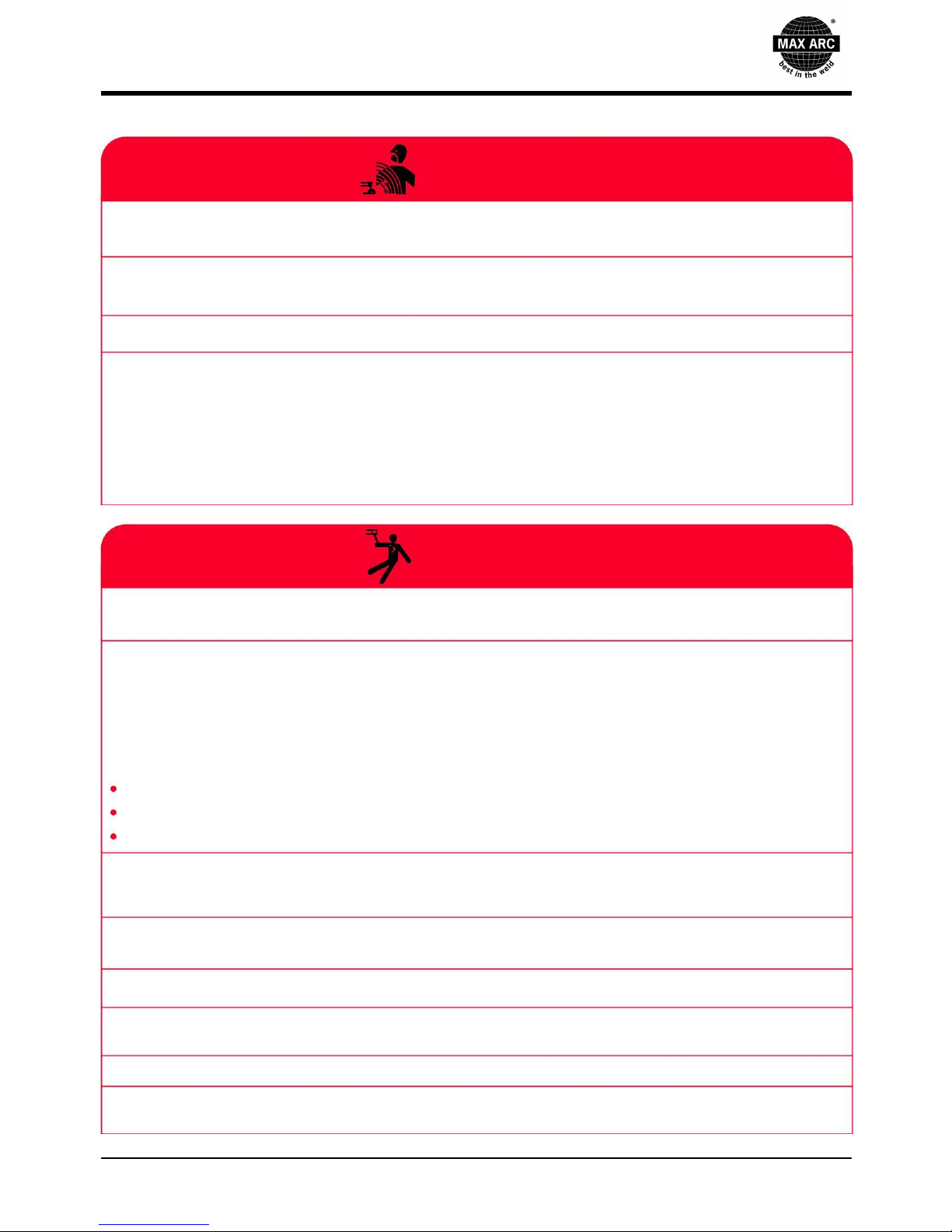
ARC WELDING CAN BE HAZARDOUS. PROTECT YOURSELF AND OTHERS FROM POSSIBLE
SERIOUS INJURY OR DEATH.KEEP CHILDREN AWAY. PACEMAKER WEARERS SHOULD
CONSULT WITH THEIR DOCTOR BEFORE OPERATING.
Read and understand the following safety highlights. For additional safety information, it is strongly
recommended that you purchase a copy of "Safety in Welding & Cutting " from the Local Welding Society.
BE SURE THAT ALL INSTALLATION, OPERATION, MAINTANANCE AND REPAIR
PROCEDURES ARE PERFORMED ONLY BY QUALIFIED INDIVIDUALS.
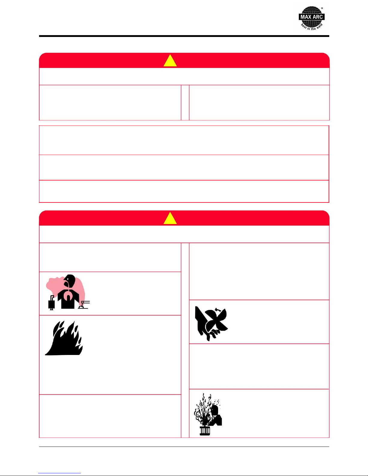
!FOR ENGINE
POWERED EQUIPMENTS
1) Turn the engine off before troubleshooting
and maintenance work unless the
maintenance work requires it to be running.
2) Operate engines in open,
well-ventilated areas or vent
the engine exhaust fumes
outdoors.
3) Do not add the fuel near an
open flame welding arc or when
the engine is running. Stop the
engine and allow it to cool
before refueling to prevent
spilled fuel from vaporizing on
contact with hot engine parts and igniting. Do not
spill fuel when filling tank. If fuel is spilled, wipe it
up and do not start engine until fumes have been
eliminated.
4) Keep all equipment safety guards, covers and
devices in position and in good repair.Keep
hands, hair, clothing and tools away from V-
belts, gears, fans and all other moving parts
when starting, operating or repairing equipment.
5) In some cases it may be necessary to remove
safety guards to perform required maintenance.
Remove guards only when necessary and
replace them when the maintenance requiring
their removal is complete. Always use the
greatest care when working near moving parts.
6) Do not put your hands near
the engine fan. Do not attempt
to override the governor or idler
by pushing on the throttle control
rods while the engine is running.
7) To prevent accidentally starting gasoline
engines while turning the engine or welding
generator during maintenance work,
disconnect the spark plug wires, distributor cap
or magneto wire as appropriate.
8) To avoid scalding, do not
remove the radiator pressure
cap when the engine is hot.
1

1.SAFETY PRECAUTIONS
ELECTRIC AND
MAGANETIC FIELDS
MAY BE DANGEROUS
1) Electric Current flowing through any conductor causes localized Electric and Magnetic Fields (EMF).
Welding Current creates EMF fields around welding cables and welding machines.
2) EMF fields may interfere with some pacemakers, and welders having a pacemaker should consult
their physician before welding.
3) Exposure to EMF fields in welding may have other health effects which are now not known.
4)All welders should use the following procedures in order to minimize exposure to EMF fields from the
welding circuit:
a. Route the electrode and work cables together. Secure them with tape when possible.
b. Never coil the electrode lead around your body.
c. Do not place your body between the electrode and work cables. If the electrode cable is on your
right side, the work cable should also be on your right side.
ELECTRIC SHOCK
CAN KILL
1)The electrode and work (or ground) circuits are electrically "hot" when the welder is on. Do not touch
these "hot" parts with your bare skin or wet clothing. Wear dry, hole-free gloves to insulate hands.
2)Insulate yourself from work and ground using dry insulation. Make certain the insulation is large
enough to cover your full area of physical contact with work and ground. In addition to the normal safety
precautions, if welding must be performed under electrically hazardous conditions (in damp locations or
while wearing wet clothing; on metal structures such as floors, gratings or scaffolds; when in cramped
positions such as sitting, kneeling or lying, if there is a high risk of unavoidable or accidental contact with
the workpiece or ground) use the following equipment:
Semiautomatic DC Constant Voltage (Wire) Welder.
DC Manual (Stick) Welder.
AC Welder with Reduced Voltage Control.
3) In semiautomatic or automatic wire welding, the electrode, electrode reel, welding head, nozzle or
semiautomatic welding gun are also electrically "hot".
4)Always be sure the work cable makes a good electrical connection with the metal being welded. The
connection should be as close as possible to the area being welded.
5)Ground the work or metal to be welded to a good electrical (earth) ground.
6)Maintain the electrode holder, work clamp, welding cable and welding machine in good, safe
operating condition. Replace damaged insulation.
7)Never dip the electrode in water for cooling.
8)Never simultaneously touch electrically "hot" parts of electrode holders connected to two welders
because voltage between the two can be the total of the open circuit voltage of both welders.
2

1.SAFETY PRECAUTIONS
9)When working above floor level, use a safety belt to protect yourself from a fall should you get a shock.
ARC RAYS
CAN BURN
1)Use a shield with the proper filter and cover plates to protect your eyes from sparks and the rays of the
arc when welding or observing open arc welding.
Head-shield and filter lens should conform to ANSI Z87. I standards.
2)Use suitable clothing made from durable flame-resistant material to protect your skin and that of
your helpers from the arc rays.
3)Protect other nearby personnel with suitable, non-flammable screening and/or warn them not to
watch the arc nor expose themselves to the arc rays or to hot spatter or metal.
FUMES AND
GASES
1)Welding may produce fumes and gases hazardous to health. Avoid breathing these fumes and
gases.When welding, keep your head out of the fume. Use enough ventilation and/or exhaust at the
arc to keep fumes and gases away from the breathing zone.
2)Do not weld in locations near chlorinated hydrocarbon vapors coming from degreasing, cleaning
or spraying operations. The heat and rays of the arc can react with solvent vapors to form
phosgene, a highly toxic gas, and other irritating products.
3)Shielding gases used for arc welding can displace air and cause injury or death. Always use
enough ventilation, especially in confined areas, to insure breathing air is safe.
4)Read and understand the manufacturer's instructions for this equipment and the consumables to be
used, including the material safety data sheet (MSDS) and follow your employer's safety practices.
MSDS forms are available from your welding distributor or from the manufacturer.
WELDING SPARKS
CAN CAUSE FIRE OR
EXPLOSION
1)Remove fire hazards from the welding area. If this is not possible, cover them to prevent the welding
sparks from starting a fire. Remember that welding sparks and hot materials from welding can easily
go through small cracks and openings to adjacent areas. Avoid welding near hydraulic lines. Have a
fire extinguisher readily available.
2)Where compressed gases are to be used at the job site, special precautions should be used to prevent
hazardous situations. Refer to "Safety in Welding and Cutting" (Standard) and the operating information
for the equipment being used.
3)When not welding, make certain no part of the electrode circuit is touching the work or
ground.
Accidental contact can cause overheating and create a fire hazard.
3

1. SAFETY PRECAUTIONS
4)Do not heat, cut or weld tanks, drums or containers until the proper steps have been taken to insure that
such procedures will not cause flammable or toxic vapors from substances inside. They can cause an
explosion even though they have been "cleaned". For information, purchase "Recommended Safe
Practices for the Preparation for Welding and Cutting of Containers and Piping That Have Held
Hazardous Substances".
5)Vent hollow castings or containers before heating, cutting or welding. They may explode.
6)Sparks and spatter are thrown from the welding arc. Wear oil free protective garments such as leather
gloves, heavy shirt, cuffless trousers, high shoes and a cap over your hair. Wear ear plugs when
welding out of position or in confined places. Always wear safety glasses with side shields when in a
welding area.
7)Connect the work cable to the work as close to the welding area as practical. Work cables connected
to the building framework or other locations away from the welding area increase the possibility of the
welding current passing through lifting chains, crane cables or other alternate circuits. This can create fire
hazards or overheat lifting chains or cables until they fail.
8)Don't use this machine to defrost pipes
CYLINDER MAY EXPLODE
IF DAMAGED
CAN BE DANGEROUS
1)Use only compressed gas cylinders containing the correct shielding gas for the process used and
properly operating regulators designed for the gas and pressure used. All hoses, fittings, etc. should
be suitable for the application and maintained in good condition.
2)Always keep cylinders in an upright position securely chained to an undercarriage or fixed support.
3)Cylinders should be located: . Away from areas where they may be struck or subjected to physical
damage. A safe distance from arc welding or cutting operations and any other source of heat, sparks,
or flame.
4)Never allow the electrode, electrode holder or any other electrically "hot" parts to touch a cylinder.
5)Keep your head and face away from the cylinder valve outlet when opening the cylinder valve.
6)Valve protection caps should always be in place and hand tight except when the cylinder is in use
or connected for use.
7)Read and follow the instructions on compressed gas cylinders, associated equipment, and CGA
publication P-l, "Precautions for Safe Handling of Compressed Gases in Cylinders," available from
the Compressed Gas Local Association.
FOR ELECTRICALLY
POWERED EQUIPMENT
1)Turn off input power using the disconnect switch at the fuse box before working on the equipment.
2)Install equipment in accordance with the National Electrical Code, all local codes and the manufacturer's
recommendations.
4

1.SAFETY PRECAUTIONS
3)Ground the equipment in accordance with the U.S. National Electrical Code and the manufacturer's
recommendations.
ELECTROMAGNETIC
DISTURBANCES MAY BE
TRANSMITTED THROUGH H.F.
ASSESSMENT OF AREA
Before installing welding equipment the user shall make an assessment of potential
electromagnetic problems in the surrounding area. The following shall be taken into account:
1)other supply cables, control cables, signaling and telephone cables; above, below and adjacent to the
welding equipment;
2)radio and television transmitters and receivers;
3)computer end other control equipment;
4)safety critical equipment, e.g., guarding of industrial equipment;
5)the health of the people around, e.g., the use of pacemakers and hearing
aids; 6)equipment used for calibration or measurement;
7)the immunity of other equipment in the environment. The user shall ensure that other equipment
being used in the environment is compatible. This may require additional protection measures;
8)the time of day that welding or other activities are to be carried out.
INSTALLATION, USE AND AREA EXAMINATION
1)The user is responsible for the installation and use of the equipment according to the manufacturer's
instructions.
2)If any electromagnetic disturbance is noticed, the user must soave the problem, if necessary with the
manufacturer's technical assistance.
3)In any case electromagnetic disturbances must be reduced until they are not a nuisance any
longer. 4)Before installing this apparatus, the user must evaluate the potential electromagnetic
problems that may
arise in the surrounding area, considering in particular the health conditions of the persons in the vicinity,
for example of persons fitted with pacemakers or hearing aids.
!WARNING
ELECTROMAGNETIC COMPATIBILITY (EMC)
1)CONFORMANCE
Products displaying the CE mark are in conformity with European Community Council Directive of 3 May
1989 on the approximation of the laws of the Member States relating to electromagnetic compatibility
(89/336/EEC). It was manufactured in conformity with a national standard that Implements a harmonized
standard: EN 50 199(EN60974-10) Electromagnetic Compatibility (EMC) Product Standard for Arc
Welding Equipment. It is for use with our Electric equipment. It is designed for industrial and professional
use.
Introduction
All electrical equipment generates small amounts of electromagnetic emission. Electrical emission may
be transmitted through power lines or radiated through space, similar to a radio transmitter. When
5

1.SAFETY PRECAUTIONS
emissions are received by other equipment, electrical interference may result. Electrical emissions may affect
many kinds of electrical equipment; other nearby welding equipment, radio and TV reception, numerical
controlled machines, telephone systems, computers, etc. Be aware that interference may result and extra
precautions may be required when a welding power source is used in a domestic establishment.
Installation and Use
The user is responsible for installing and using the welding equipment according to the manufacturer's
instructions. If electromagnetic disturbances are detected then it shall be the responsibility of the user of
the welding equipment to resolve the situation with the technical assistance of the manufacturer. In some
cases this remedial action may be as simple as earthing (grounding) the welding circuit, see Note. In
other cases it could involve constructing an electromagnetic screen enclosing the power source and the
work complete with associated Input filters. In all cases electromagnetic disturbances must be reduced
to the point where they are no longer troublesome.
Note: The welding circuit may or may not be earthed for safety reasons according to national codes.
Changing the earthing arrangements should only be authorized by a person who is competent to assess
whether the changes will increase the risk of injury, e.g., by allowing parallel welding current return
paths which may damage the earth circuit of other equipment.
Assessment of Area
Before installing welding equipment the user shall make an assessment of potential electromagnetic
problems in the surrounding area. The following shall be taken into account:
a)other supply cables, control cables, signaling and telephone cables; above, below and adjacent to the
welding equipment;
b)radio and television transmitters and receivers;
c)computer end other control equipment;
d)safety critical equipment, e.g., guarding of industrial equipment;
e)the health of the people around, e.g., the use of pacemakers and hearing aids;
f)equipment used for calibration or measurement;
g)the immunity of other equipment in the environment. The user shall ensure that other equipment being
used in the environment is compatible. This may require additional protection measures;
h)the time of day that welding or other activities are to be carried out.
2.EMISSION REDUCTION METHODS
Mains Power Supply
The welding power source must be connected to the supply mains according to the manufacturer's
instructions. In case of interference, it may be necessary to take further precautions like the filtering of the
mains power supply. It is also necessary to consider the possibility to shield the power supply cable.
Welding Power Source Maintance
The welding power source needs routine maintenance according to the manufacturer's instructions.
When the equipment is working, all the access and operating doors and covers must be closed and fixed.
The welding power source must not be modified in any way.
Welding and Cutting Cables
The welding cables must be kept as short as possible, positioned near one another and laid at or
approximately at ground level.
Equipotential Connection
The earth connection of all the metal component in the welding installation and near it must be taken in
consideration. However, the metal component connected to the work-piece will increase the risk of
electric shock for the operator, if he touches said metal component and the electrode at the same time.
shock for the operator, if he touches said metal component and the electrode at the same time. Therefore,
6

1.SAFETY PRECAUTIONS
the operator must be insulated from all the earthed metal components. The equipotential connection
must be made according to the national regulations.
EARTHING THE WORKPIECE
When the workpiece is not earthed for electrical safety reasons or due to its size and position, Care
should be taken to prevent the earthing of the workpiece increasing the risk of injury to users, or
damage to other electrical equipment. the earthing of the workpiece may reduce the emissions in
some,but not all instances. It is important to remember that the earthing of the workpiece should
neither increase the risk of accidents for the operators, nor damage other electric equipment. The
earthing must be made according to the national regulations.
SCREENING AND SHIELDING
Selective screening and shielding of other cables and equipment in the surrounding area may alleviate
problems of interference. Screening of the entire welding installation may be considered for special
applications.
RISK
ANALYSIS
Risks posed by the machine
Solutions adopted to prevent them
Risk of wrong installation.
A manual with the instructions for use has been
Electrical risks.
produced for this purpose.
Application of the EN 60974-1 Standard.
Risks connected with electromagnetic disturbances
Application of the EN 50199(EN60974-10)
produced by the welding power source and induced
Standard.
on the welding power source.
7

2.MAIN USAGE AND THE RANGE OF USAGE
MAX-ARC 250 AC/DC TIG Welder is a triple functional machine used as MMA, AC TIG, DC TIG (PULSE TIG)
Welder. All ferrous metals, copper, titanium, stainless steels, aluminum and alloyed materials can be used for full
range of welding in all positions. The Welding Current is very stable, and it is also step-less adjustable. The
welding performance is very good and the welding seam is nice, very few spatters and low noise occurs during
welding. It's light in weight , compact and portable. It's a double inverter system, heavy duty designed, used
ATMEGA SCM controlling system and famous brand IGBT transistors. It's particularly suitable for the welding
jobs for the enterprises of pressure tanks, vessel buildings, constructions, petrochemicals etc. It's a premier TIG
welder by comparing with the traditional types.
8

3.OPERATION CONDITIONS AND WORK SURROUNDING
1)Operating Conditions:
√Voltage of power source: AC 220/230/240 V ±10%
√Frequency: 50/60Hz
√Reliable grounding protections
2)Work Surrounding:
▶Relative Humidity: not more than 90 %(average monthly temperature not more than 20℃).
▶Ambient Temperature: -10℃~ 40℃.
▶The welding place should not have harmful gas, chemicals, molds and inflammable matter, explosive
and corrosive medium, and no big vibration and bump to the welder.
▶Avoiding water. Operating in rain is not allowed.
9

4.MAIN TECHNICAL SPECIFICATIONS
Technical specifications
Item No
Max Arc 200
Max Arc 250
Rated Input Voltage
1PH ~ 230V +15%
1PH ~ 230V +15%
Max. Load Power Capacity
TIG: 4.5KVA
TIG: 6.3KVA
MMA: 5.6KVA
MMA: 7.1KVA
Rated Duty Cycle (40℃)60%
TIG: 200A/18V
TIG: 250A/20V
MMA: 160A/26.4V
MMA: 200A/28V
100%
TIG: 160A/26.4V
TIG: 200A/18V
MMA: 130A/25.2V
MMA: 160A/26.4V
Welding Current/Voltage Range
TIG: 5A/10.2V~200A/18V
TIG: 5A/10.2V~250A/20V
MMA:10A/20.4V~160A/26.4V
MMA:10A/20.4V~200A/28V
Open Circuit Voltage
10V
10V
Power Factor
0.73
0.73
Efficiency
80%
80%
Peak Current
5A~200A
5A~250A
Pulse
Base Current
5A~200A
5A~250A
Pulse Frequency
0.2Hz~200Hz
0.2Hz~200Hz
Pulse Width (Ratio)
1~100%
1~100%
AC
AC Frequency Range
20Hz~200Hz
20Hz~200Hz
TIG
TIG
AC Clean Width (AC Balance)
+40~-40
+40~-40
AC Clean Ratio (AC Bias) %
+30~-50
+30~-50
MIX
MIX Frequency:
0.1Hz~5Hz
0.1Hz~5Hz
TIG
DC Balance: (%)
10~90
10~90
Arc-starting Current
10A~160A
10A~200A
Crater-filling Current
5A~200A
5A~250A
Current Up-slope Time
0.1S~10S
0.1S~10S
Current Down-slop Time
0.1S~15S
0.1S~15S
Pre-Gas Time
0.1S~10S
0.1S~10S
Flow-Gas Time
0.1S~15S
0.1S~15S
Spot Arc Time
0.1S~10S
0.1S~10S
MMA
Arc Force
10A~100A
10A~160A
Hot Start Time
2S
2S
Hot Start Current
5A~100A
5A~160A
Dimension (LxWxH)
490X230X385mm
490X230X385mm
Weight (KG)
23KG
23KG
Water-cooling Unit: WC-100 (optional)
Operating Voltage
230V 50/60Hz
Rated Power
260W
Cooling Power
1.5KW(1L/MIN)
Maximum Pressure
0.3MPA/60HZ
Recommended Cooling Liquid
20%~40% ethanol/water
Tank Volume
6.5L
10

5.SKETCH MAPS OF THE PANELS
Panel & connections:
3
1
2
4
5
6
Item
Symbol
Description
1
Control Panel
2
Output connectors
3
Power Switch
4
Input power cable: 1~ phase 220-240V, 50/60Hz.
5
Gas input connector
6
Ground/Earth connector
11

6.DESCRIPTION OF THE CONNECTIONS
2
1
4
5
6
7
3
12
Item
Symbol
Description
1
Gas Bottle
2
power supply/phase 220~240V,50/60Hz
3
Foot Pedal
4
Connection socket, "+" welding current
• TIG: Connection for workpiece lead
• MMA: Electrode holder or workpiece lead connection
5
Connection socket
5-pole: Standard TIG torch control lead
Foot pedal control lead
6
M16X1.5 ” connecting nipple
Shielding gas connection (with yellow insulating cap) for TIG
7
_
Connection socket, "-" welding current
TIG: TIG welding torch connection
MMA: Electrode holder or workpiece lead connection

7.SPECIAL FEATURES, DEFINITIONS & GLOSSARY
Special Features:
Item
Symbol
Description
1
MIX TIG:
In a cycle time that mixed with EN/EP output (AC TIG) and EN output (DC TIG).
2
Electrode Dia. selection
3
Spot Welding Mode
4
DC +/- converter output arc-starting of AC TIG process MIX TIG process.
5
AC Wave Type
6
MIX TIG mode for every pulse cycle.
13

7.SPECIAL FEATURES ,DEFINITIONS & GLOSSARY
Special Features:
Item Symbol Description
AC Wave Control System:
7
AC Frequency Control
AC Balance Control
Independent AC Amperage Control
8
Memory with capacity of 10 sets parameters.
14

7.SPECIAL FEATURES, DEFINITIONS & GLOSSARY
AC Waveshape Controls
AC Frequency control
Controls the width of the arc cone.
Increasing the AC Frequency provides a
more focused arc with increased
directional control.
Note: Decreasing the AC Frequency
softens the arc and broadens the weld
puddle for a wider weld bead.
Wider bead,good penetration ideal for buildup work
Wider bead and cleaning acting
+
Narrower bead for fillet welds
and automated applications
Wider bead and cleaning acting
+
AC Balance Control
Controls arc cleaning action. Adjusting the
Wider bead,good penetration ideal for buildup work
% EN of the AC wave controls the width of
the etching zone surrounding the weld.
Note: Set the AC Balance control for
adequate arc cleaning action at the sides
Wider bead and cleaning action
and in front of the weld puddle.
AC Balance should be fine tuned
+
according to how heavy or thick
the oxides are.
%
Wider bead,good penetration ideal for buildup work
Narrow bead, with no visible cleaning
+
%
Independent AC
Amperage Control
More current in EP than EN: Shallower penetration
More current in EN than EP: Deeper penetration
and faster travel speeds
Allows the EN and EP amperage values to be set
independently. Adjusts the ratio of EN to EP
amperage to precisely control heat input to the
work and the electrode. EN amperage controls the
level of penetration, while EP amperage
dramatically effects the arc cleaning action
along with the AC Balance control.
+A
A
Wider bead and cleaning action
+
Narrow bead, with no
visible cleaning
+A
+
A
15

7.SPECIAL FEATURES, DEFINITIONS & GLOSSARY
MIX TIG Control:
Features of MIX TIG:
The AC current can get a very good clearance,
and DC current can get a deeper penetration.
Use the MIX TIG we can get an excellent Arc
Concentration, can be carried out the excellent
welding performance from thin to thick plate.
1) Nice weld appearance, deep penetration.
2) Excellent Arc Concentration.
3) Substantially reduce the electrode consumption.
MIX TIG
AC
DC
AC TIG
MIX TIG Frequency (Hz):
the cycle time of MIX TIG in 1 second.
Adjustable range: 0.1-10Hz.
AC DC
(1Hz)
MIX Frequency
MIX TIG Balance (DC) %:
DC Balance (%) = (tad/Tmix) x 100
AC DC
tad
(MIX Cycle Time:1Hz)
16

7.SPECIAL FEAURES, DEFINITIONS & GLOSSARY
Definitions & Glossary
Item Symbol Description
1
Process Selection
2
Tungsten Electrode Dia.
From 2.0mm to >4.0mm
3
Pulse ON/OFF selection.
4
2T/4T holding mode or Spot Welding mode selection
17

7.SPECIAL FEATURES, DEFINITIONS & GLOSSARY
Definitions & Glossary
Item
Symbol
Description
5
DC +/- converter output arc-starting of AC TIG process MIX TIG process.
6
Select the AC wave type: square wave or sine wave.
7
MIX TIG adjusting
8
MIX TIG: Pulse Frequency.
9
MIX TIG:DC output time (DC Balance).
10
Push to select AC Freq./AC Balance/Independent EN/EP Amperage for adjusting.
11
AC Frequency.
12
AC Balance.
13
Independent AC Amperage Control (EN/EP Balance %).
14
Remote: used for foot pedal or Remote torch.
Local: adjusted Currents by face panel.
15
Memory with capacity of 10 sets parameters.
16
Function sequence (see next chapter)
18
Table of contents
Popular Welding System manuals by other brands

XTline
XTline XT103001 Original instruction manual

Miller Electric
Miller Electric 456 CC owner's manual

Kühtreiber
Kühtreiber FENIX 250 PFC AC/DC user manual

Razorweld
Razorweld KUMJRRW110DC operating manual

EWM
EWM Picotig 200 puls TG operating instructions

Lincoln Electric
Lincoln Electric NA-5N Service manual