Maxair Velox Revolution II User manual

Velox Revolution II Specs:
Metric Imperial
Wingspan : 1730 mm 68 in
Wing Area : 62 dm2965 in2
Length : 1460 mm 57.5 in
Recommended Engine : 2C - .91 to 1.0 4C - .91 to 1.1
Radio : 4 Channels – 6 servos (Hi-torque recommended)
Weight : 3.7 to 4 kg 8.1 to 8.8 lbs
Maxair Model Products
https://www.maxairrc.com
www.maxairrc.com Page 2 of 19
Introduction
The MAXAIR Velox Revolution II was designed with nothing but performance in mind. You name it, it
can do it. Whether your thing is down on the deck 3D, or the precision required while performing scale
aerobatic, the MAXAIR Velox Revolution II is for you! The MAXAIR Velox Revolution II tracks as
straight as an arrow but will tumble with the best of them. Its super light weight makes for an extremely
low wing loading and extreme performance.
Let’s start building!
Using the Assembly Manual
The assembly of the MAXAIR Velox Revolution II is very straightforward. Follow these instructions
and your MAXAIR Velox Revolution II should be ready to fly in 4 to 6 hours.
ÅBe extra careful when you encounter items marked with the red alert icon.
ÅItems denoted with the green tip icon offer suggestions that may be helpful in assembling
your model.
Read through the entire manual before starting the assembly of your model
MAXAIR Model Products Warrantee
MAXAIR Model Products guarantees this product to be free from defects in both material and
workmanship at the time of purchase. The warranty does not cover any component damaged by use or
modification. MAXAIR Model Products shall in no case be liable for more than the original cost of this
product. MAXAIR Model Products reserves the right to modify this warrantee without notice.
No liability shall be assumed or accepted by MAXAIR Model Products for any damage caused or
resulting from the use by the user of the final assembled product. By using this product, the user accepts
all resulting liability. If the buyer is not ready to accept the liability associated with the purchase and use
of this product, the buyer is advised to return the product in new and unused condition to the place of
purchase.
To make a warrantee claim, send the defective part to:
MAXAIR Model Products
105 Barrington Cr.,
Moncton, NB
Canada
E1G 4V4
You may contact MAXAIR Model Products through their support website at: http://maxairrc.com
WARNING
Radio Controlled Model Aircraft are not toys! This model is a high performance model and can cause
harm if misused. This plane is not for beginners. Only experienced pilots should fly it.
Fly in open spaces away from structures and people. Always do a pre-flight check of the aircraft before
flying it. Always follow all safety precautions set forward by MAAC and the AMA.
Have fun and be safe!
www.maxairrc.com Page 3 of 19
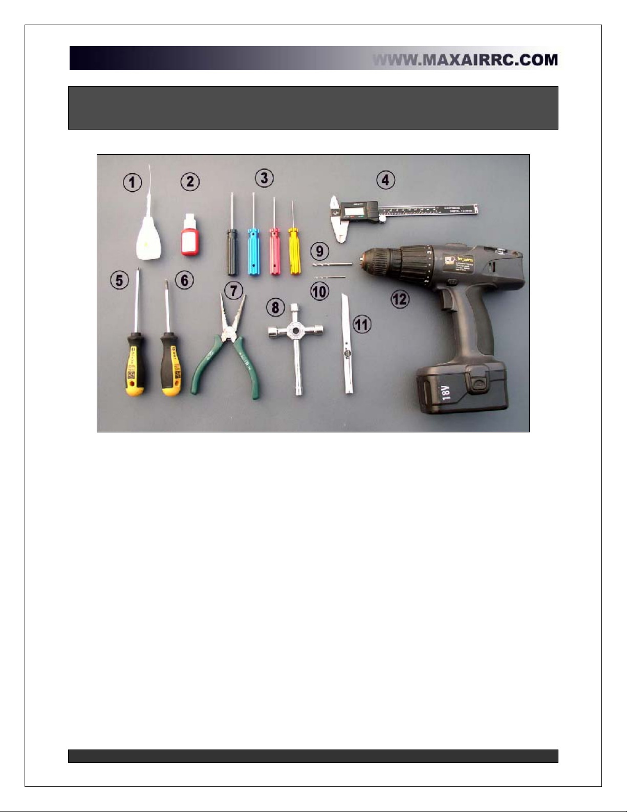
Required Items to complete
(The following items are not included in the kit and must be purchased
separately)
1. CA (thin and medium or thick)
2. Thread Locking Compound
3. Hex head screw drivers
4. Vernier Callipers
5. Flat head screw driver
6. Phillips head screw driver
7. Needle nose pliers
8. Plug wrench or other wrenches
9. 4mm drill bit
10. 1.5mm drill bit
11. Hobby knife
12. Drill
Items required but not shown above:
-30 min Epoxy
-Covering Iron
-Servo Extensions
-Foam rubber padding
-Double sided padded tape

www.maxairrc.com Page 4 of 19
Parts included in the kit
Package
b
Part Description Quantity Condition
Fuselage 1pc Finished
Rudder servo mount 1pc Included
Cockpit hatch/cover 1pc Included
Fix screw M3x8 4pcs Included
Belly pan 1pc Included
1 Fuselage
Screws - M3x15 2pcs Included
Main wing 1set Finished
Ailerons 1set Included
CA hinges 8pcs Included
Nylon screw M6x25 4pcs Finished
Wingnuts - M6 4pcs Included
2 Main wing
Carbon wing tubing - 22x750mm 1pc Included
Horizontal stabilizers & Elevators 1set Finished
Rudder 1pc Finished
3
Horizontal
stabilizers and
rudder CA hinges 4pcs Included
Cowl 1pc Finished
Blind nuts - M3 4pcs Finished
4 Cowling
Screws – M3x10 4pcs Included
Wheels D=70mm 2pcs Included
Wheel pants 1set Included
Blind nuts - M4 3pcs Finished
Aluminum landing gear 1pc Included
Screws M4x20 3pcs Included
Washers - D4 4pcs Included
Screws - M4x40 2pcs Included
Lock Nuts - M4 4pcs Included
5 Wheel
Tail wheel 1set Finished
Engine mount 1set Included
Blind nuts - M4 4pcs Included
Screws - M4x25 4pcs Included
Washers - D4 4pcs Included
Screws for engine - M4x25 4pcs Included
6 Engine mount
Nuts for engine - M4 4pcs Included
Canopy 1pc Finished
7 PVC Canopy Canopy screws - M3x8 4pcs Included
Control horns 2sets Included
Fix screw M3x8 6pcs Included
8 Aileron hardware
Carbon/steel control rods -120mm 2sets Finished
www.maxairrc.com Page 5 of 19
Carbon tube - D8x128 1pc Included
Carbon tube - D8x213 1pc Included
Screws - M3x20 2pcs Included
Control horns 2sets Included
Screws - M3x8 6pcs Included
Carbon/steel control rods -200mm 1set Finished
9
Elevator and
vertical stabilizer
hardware
Carbon/steel control rods 260mm 1set Finished
Fuel tank -550cc 1set Included
Nylon bind tape 300mm 1pc Included
10 Fuel tank
Foam tape - 120mm 2pcs Included
Metal clevis - M3 4pcs Included
Metal control rod - M3 4pcs Included
Pull-pull wire - D1x1800mm 1pc Included
Pull-pull aluminum control horn 2sets Included
Screws - M3x18 1pc Included
11 Rudder hardware
Crimp metal tubing 4pcs Included
Manual 1pc
Included
Heat shrink tubing 300mm 1pc Included
Double sided foam tape 2pcs Included
Nylon tape 200mm 4pcs Included
12 Manual
Nylon tape 250mm 2pcs Included
www.maxairrc.com Page 6 of 19
Main Wing Assembly
Step 1 – Install the ailerons
a. Remove the aileron from the wing.
b. Adjust the CA hinges so that they are
aligned properly in the hinge slots.
c. A pin can be inserted through the center
of the hinge to make sure it stays
centered.
d. Slide the aileron onto the hinges and butt the
aileron up against the wing.
e. Make sure there is no gap between the
aileron and the wing.
f. Drip some CA onto the CA hinges from the
top and the bottom of the wing.
g. Repeat for the opposite wing.
Be careful not to drip any CA onto the wing
covering.
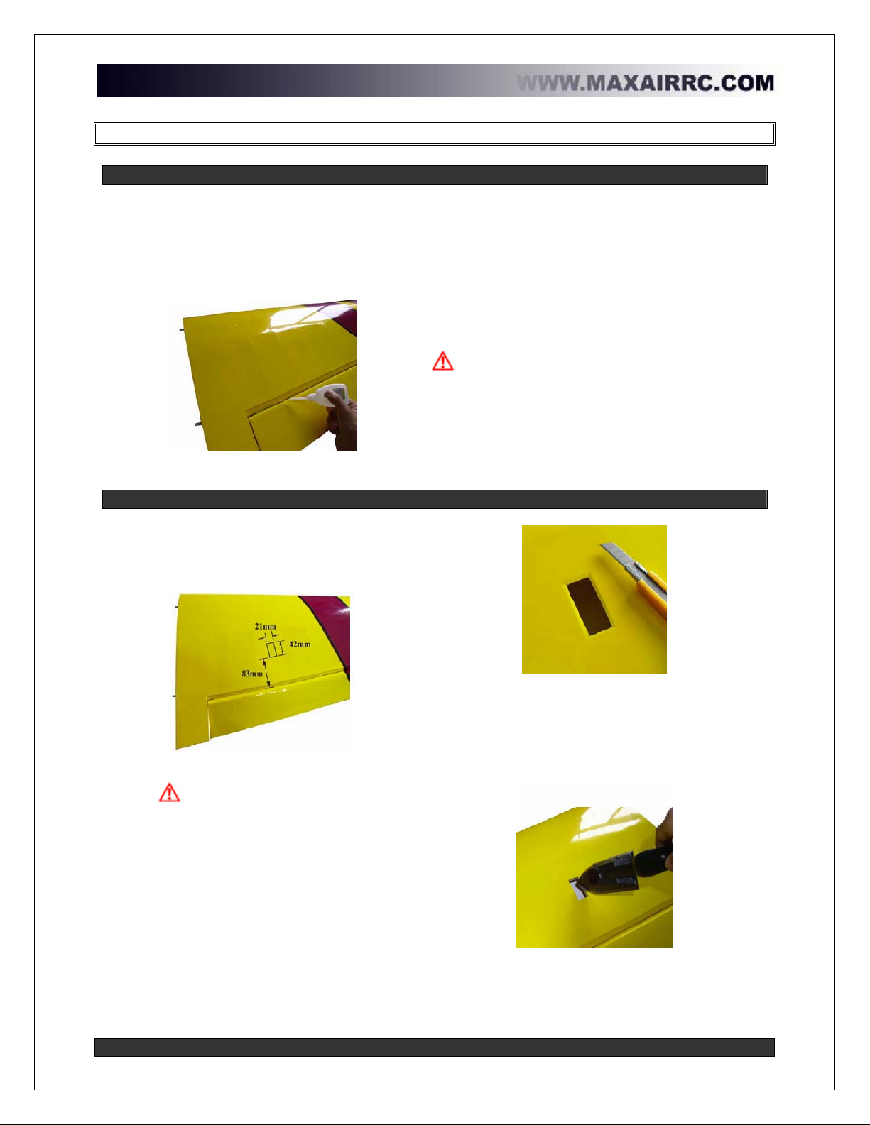
Step 2 – Prepare the servo cutout
a. Locate the servo cutout on the bottom of
the wing. The dimensions can be seen
in the picture below.
Aileron servo cutout dimensions
b. When cutting the covering to install
the servo, make sure to leave a 3mm
(1/8in) wide strip of covering that can be
ironed down in the servo cutout.
c. Cut the covering.
Leave a 3mm (1/8in) strip around the cutout
d. Iron down the overlapping covering and
around the servo cutout to make sure the
covering is secure.
e. The cutout allows for a standard size servo.
A high-torque servo is recommended.
Iron down the overlapping covering
f. Repeat for the opposite wing.

www.maxairrc.com Page 7 of 19
Step 3 – Install the aileron servos
Items required
a. One servo is required for each aileron.
(High-torque servos are required due to
the large size ailerons.)
b. Prepare the servos by installing the
rubber grommets.
c. It is important to note that the
copper inserts that are fit into the rubber
servo grommet must be installed with the
flange facing downwards. See image
below.
Flange on copper inserts facing downwards
d. A servo extension is required. It is
always a good idea to secure the servo
connector to the extension. We like to
use heat shrink tubing to ensure a
secure installation. See image below.
Secure servo connector to servo extension
e. Run the servo extension through the servo
cutout and out to the root of the wing panel.
f. Insert the servo into the cutout. Make sure
the servo goes in freely.
g. Mark and drill 1.5mm holes for the servo
screws by using the servo as a guide.
h. Do not try to screw servo screws
without drilling pilot holes first as this will
crack the servo mount.
Mark and drill 1.5mm pilot holes
i. A drop of thin CA in the pilot hole will harden
it and make for a strong servo installation.
Strengthen pilot holes with CA
j. Once the CA is dry, screw the servo in place.
k. Repeat for the opposite wing.
www.maxairrc.com Page 8 of 19
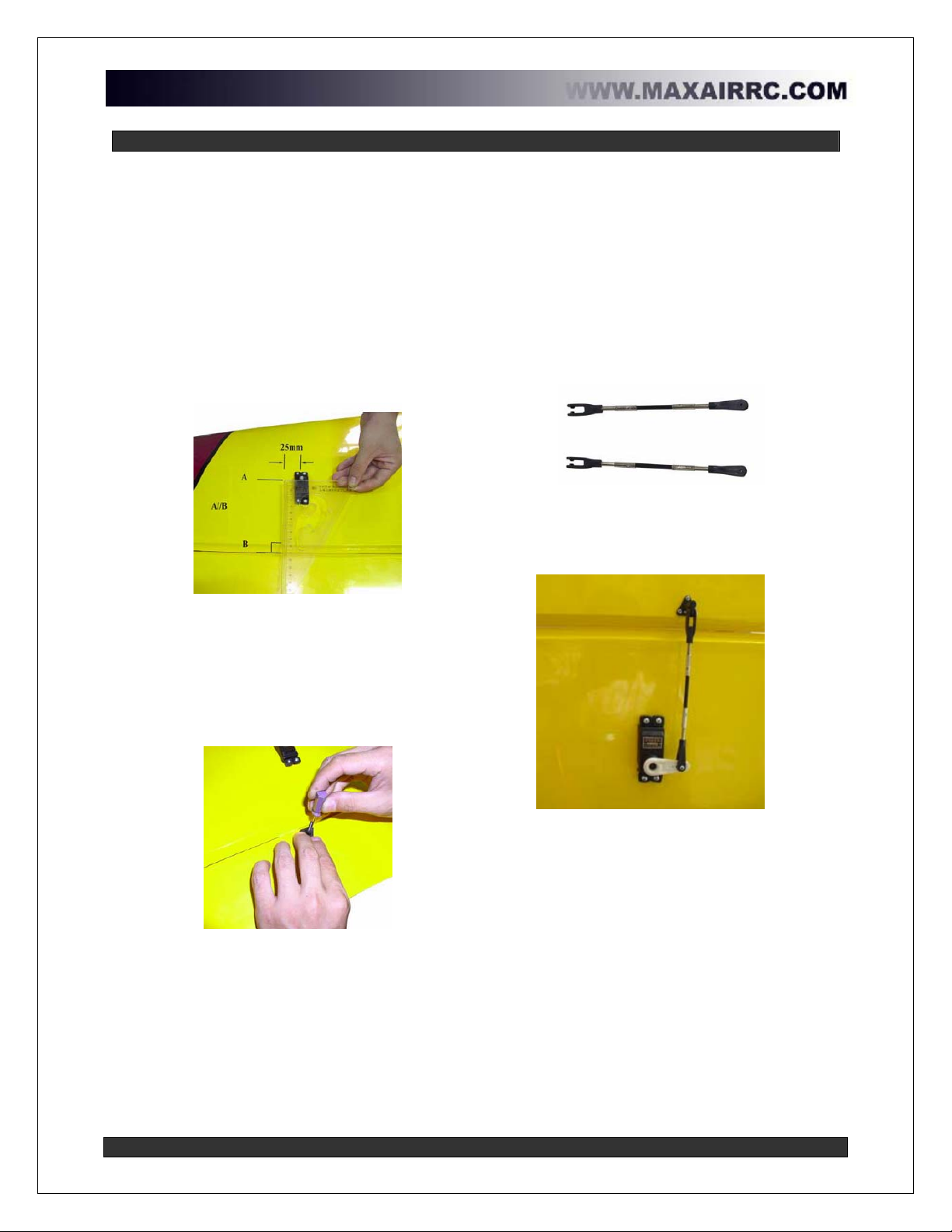
Step 4 – Install aileron linkage
It is very important that the aileron control
linkage be installed at a 90º angle to the
aileron hinge line.
a. Place a servo horn onto the servo output
shaft. The distance between the center
of the servo output shaft and the control
rod will vary depending on your flying
style. For 3D flying, a distance of 25mm
(1in) is required.
b. Using a square, determine the mounting
location of the aileron control horn.
c. Line A must be parallel to line B (hinge
line) to ensure a square installation.
How to square aileron linkage
d. Once you have determined where the
aileron control horn must be installed,
use a control horn to mark where the
pilot holes must be drilled.
Note: The control horn must be at the
very edge of the aileron.
Mark pilot holes for control horn
e. Drill the pilot holes and strengthen holes with
thin CA. Once dry, screw the control horn to
the aileron.
f. The control horns supplied with the kit are
infinitely adjustable which allow for maximum
adjustment to your flying style.
g. Adjust the length of the control rod so that
the aileron is at neutral position when the
aileron servo is at neutral,
Aileron control Horns
h. Repeat for the opposite wing.
Completed aileron linkage assembly

www.maxairrc.com Page 9 of 19
Fuselage Assembly
Step 5 – Prepare the servo cutouts
The first step in assembling the fuselage is to
prepare the servo cutouts. The MAXAIR Velox
RII was designed to allow for multiple servo
configurations. Pull-pull hardware is included
with the kit, but if required, the rudder servo can
be installed in the tail.
a. Cut the covering off of the left side
elevator servo cutout. Don’t forget to
leave a 3mm (1/8) wide strip around the
inside of the cutout that you will iron
down to the sides of the cutouts.
The cutout can be found using the
dimension in the image below.
Left side elevator servo cutout location
b. Repeat with the right side servo cutout
using the dimensions in the image
below.
Right side elevator servo cutout location
If you opt to put the rudder servo in the tail, the
rudder servo cutout can be found on the left side
of the fuselage below and behind the elevator
servo cutout as seen in the picture below.
The pull-pull wire exit is also shown in the picture
below.
Elev., rudder and pull-pull cutouts
Do not remove covering from all servo cutouts
and exit holes. Only remove the covering from the
servo cutouts and exit holes required.
www.maxairrc.com Page 10 of 19
Step 6 – Install the rudder
a. The rudder is installed exactly like the
ailerons were installed. Start by
adjusting the CA hinges so that the line
properly in the hinge slots.
b. A pin can be inserted through the center
of the hinge to make sure it stays
centered.
Install the rudder to the fuselage
c. Slide the rudder onto the hinges and butt the
rudder up against the vertical stabilizer.
d. Make sure there is no gap between the
rudder and the vertical stabilizer.
e. Drip some CA onto the CA hinges from each
side of the rudder.
Be careful not to drip any CA onto the covering.
The rudder must be able to move freely without any
binding.
Step 7 – Install the landing gear, wheels and wheel pants
a. Remove the belly pan from the fuselage.
b. Install the landing gear with the supplied
screws. Use some removable thread
locking compound to secure the screws
to the blind-nuts.
Install the landing gear
c. Next, prepare the wheels. Insert the
screw included with the wheels through
the wheel hub. Screw a locknut onto the
screw. The wheel must be free to rotate.
Wheel assembly
d. Slide the wheel into the wheel pant and fix
the wheel pant assembly to the landing gear
using the remaining locknut.
Double sided padded tape placed between the
landing gear and the wheel pant assembly makes for an
even stronger assembly.

www.maxairrc.com Page 11 of 19
Step 8 – Install the tailwheel assembly
a. Insert the tail wheel axle wire through the
tail wheel mount. Bend the tail wheel
axle wire as shown in picture below.
Make sure that the tail wheel axle wire
rotates freely in the bracket.
b. Drill a 1.5mm hole at a distance of 50mm
(2in) from the leading edge of the rudder
as shown in picture below. The hole
should be about 10mm (0.4in) deep.
Drill 1.5mm hole 50mm (0.4in) from rudder leading
edge
c. Drip some thin CA into the hole to
strengthen it.
d. Once dry, fix the tail wheel axle wire
retainer into the 1.5mm hole. This will
turn the tail wheel when the rudder turns.
Tail wheel axle wire bracket
e. Place the tail wheel bracket on the bottom
rear of the fuselage and mark the where you
will need to drill the pilot holes.
f. Drill 1.5mm holes and drip some thin CA into
the holes to strengthen.
g. Once dried, mount the tail wheel bracket to
the fuselage with the included screws.
Mount the tail wheel bracket to the fuse
h. The portion of the tail wheel axle wire that
goes through the axle wire retainer should
be allowed to free float.
i. Mount the tail wheel and secure the wheel
collar in place.
Mount the tail wheel
j. Make sure that the rudder assembly can
move freely in both directions.
Rudder must move freely in both directions
Be careful not to drip any CA onto the covering
when strengthening the pilot holes.

www.maxairrc.com Page 12 of 19
Step 9 – Install the elevator
a. The elevator halves are installed exactly
like the ailerons and the rudder. Start by
adjusting the CA hinges so that they line
up properly in the hinge slots.
b. A pin can be inserted through the center
of the hinge to make sure it stays
centered.
Install the elevator halves
c. Slide the elevator half onto the hinges and
butt it up against the horizontal stabilizer.
d. Make sure there is no gap between the
elevator and the horizontal stabilizer.
e. Drip some CA onto the CA hinges from each
side of the elevator.
f. Repeat for the opposite elevator half.
Be careful not to drip any CA onto the covering.
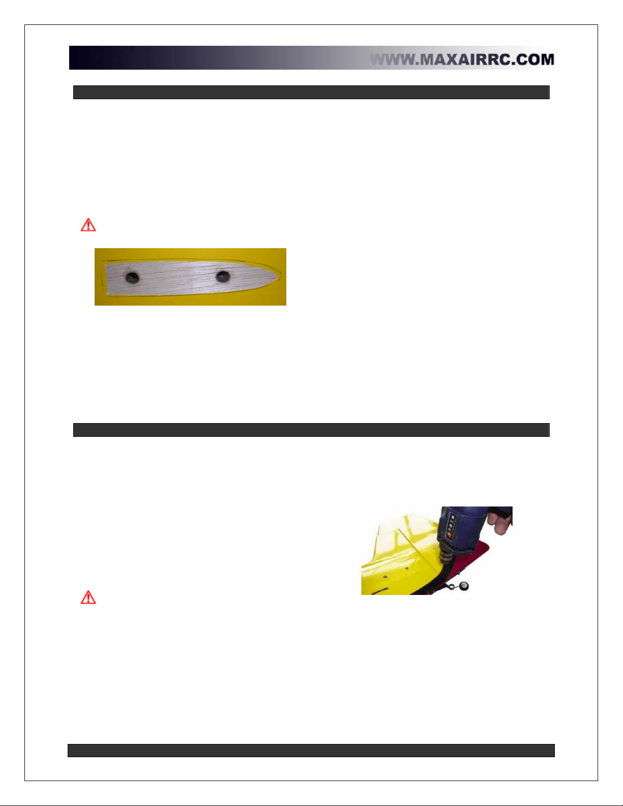
Step 10 – Install the elevator control horns
To install the elevator control horns, we will
temporarily mount the horizontal stabilizers so
we can get proper alignment with the elevator
servos.
a. Locate the holes in the rear of the
fuselage where the 8mm (0.31in)
carbon fiber support tubes are slid
through the fuse. Remove the
covering from these holes and slide
the horizontal stabilizer 8mm carbon
fiber support tubes through them. The
shorter of the two goes in the front
hole.
Locate the horizontal stab. support tube holes
b. Slide one of the elevator halves onto the 8mm
(0.31in) carbon support tubes.
c. Place a servo in the elevator servo cutout so
you can align the control horn with the servo
horn.
d. Once aligned, mark and drill the holes for the
elevator control horn. Drip some thin CA into
the holes to strengthen.
e. Once dried, mount the elevator control horn to
the elevator.
Mount the elevator control horn
f. Repeat for the opposite elevator half.
Be careful not to drip any CA onto the covering.
www.maxairrc.com Page 13 of 19
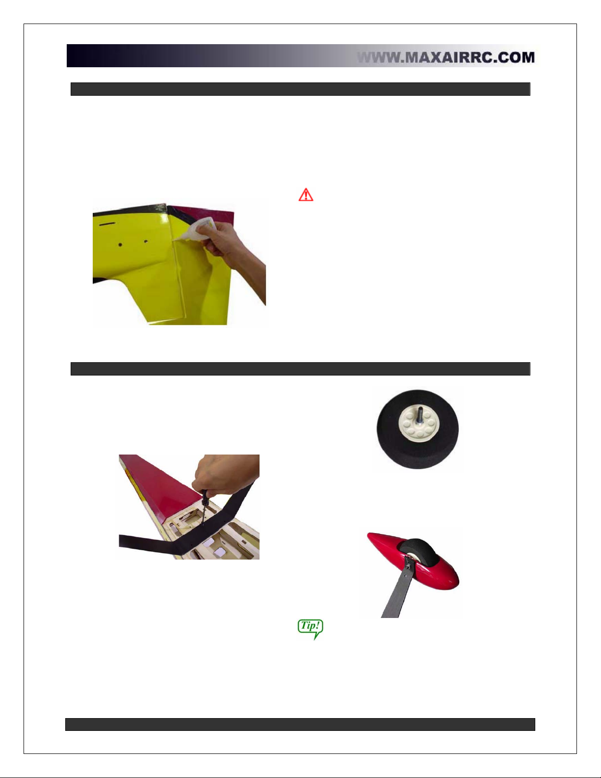
Step 11 – Install the horizontal stabilizers
a. The horizontal stabilizers are mounted
onto the 8mm (0.31in) carbon fiber
tubes as described earlier.
b. Mark around the horizontal stabilizer
on the side of the fuselage.
c. Cut the covering inside of the marked
off area. Make sure to leave a 3mm
(1/8in) strip inside of the marked off
area as shown below. Do both sides.
Make sure to only cut the covering and
not cut into the wood.
Remove the covering inside of the marked off area
d. Test fit the horizontal stabilizers onto
the 8mm (0.31in) carbon fiber tubes.
Once you are happy with the fit, you
are ready to glue the horizontal
stabilizer to the fuselage.
e. The next step is very important. You must
prepare your epoxy, coat the 8mm (0.31in)
carbon fiber tubes and the size of both
horizontal stabilizers with epoxy and assemble
them. 30 minute epoxy is recommended for
this step. Make sure all your parts are in place
and you have a rag and some alcohol or
acetone to wipe up the excess epoxy before it
cures.
¾Mix the epoxy.
¾Coat the outside of the carbon fiber
tubes with epoxy and slide into the
fuselage support holes.
¾Coat the sides of each horizontal
stabilizer with epoxy.
¾Slide the horizontal stabilizers in
place.
¾Wipe off the excess epoxy that
squeezes out when horizontal
stabilizers are slid into place.
¾Secure horizontal stabilizers to
fuselage while epoxy cures.
Step 12 – Install the rudder servo and pull-pull control horn
a. Align the rudder pull-pull control horn
with the exit cutout in the fuselage and
the rudder servo so that the pull-pull wire
makes a straight line out of the fuselage.
b. The distance from the pull-pull control
horn and the leading edge of the rudder
should be such that hole in the plastic
part of the pull-pull control horn is
aligned with the hinge line.
c. When satisfied with the placement of the
control horn, drill a 3mm hole through
the rudder.
The hole must be drilled perfectly straight
so that the control horn is as the same position
on both sides of the rudder.
d. Drip some thin CA into the hole to strengthen
it.
Drill pull-pull control horn hole
Continued…
www.maxairrc.com Page 14 of 19
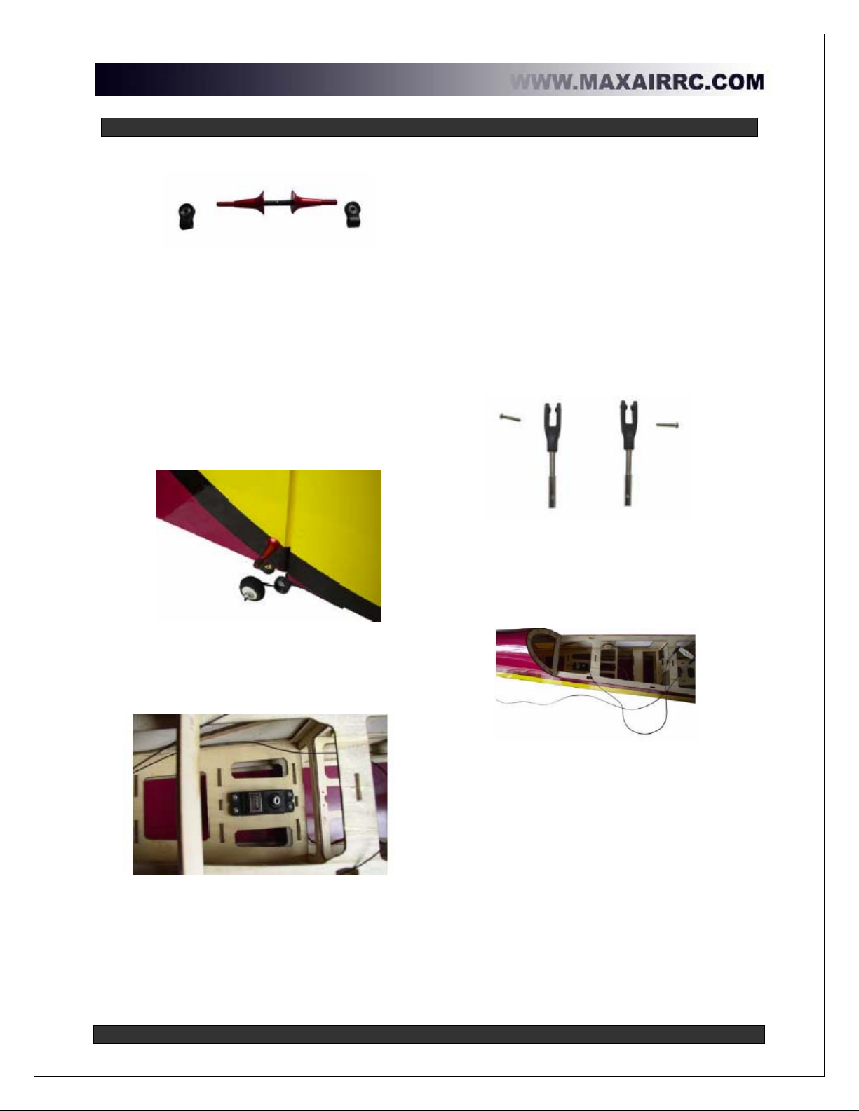
Step 12 (Continued…) – Install the rudder servo and pull-pull control horn
Pull-pull control horn hardware
e. Once the CA has dried, unscrew the
aluminum support pieces from the pull-
pull control horns and screw the
threaded rod through hole in the rudder.
f. Replace the aluminum support pieces on
each side of the threaded rod making
sure the same amount of rod sticks out
of each side of the rudder.
g. Screw the plastic end pieces onto the
threaded rod. These can be infinitely
adjusted to suit your flying style.
Completed pull-pull control horn assembly
h. Place the rudder servo in the rudder
servo cutout in the main area of the
fuselage.
Rudder servo in place
i. Mark and drill the holes with a 1.5mm drill
bit. Drip some thin CA into the holes to
strengthen them.
j. When dry, screw the rudder servo to its
mount.
k. Prepare the pull-pull clevises by screwing
them onto the threaded end pieces.
Pull-pull clevises
l. Run the pull-pull wires through the fuselage
and out the exit cutouts to adjust the length.
m. Once the length of wire is determined, run
the wire through the threaded end pieces.
Run the pull-pull wire through the fuselage
n. When the proper length has been set, crimp
metal tubing over the pull-pull wire to secure.
Continued…

www.maxairrc.com Page 15 of 19
Step 12 (Continued…) – Install the rudder servo and pull-pull control horn
o. Adjust the pull-pull wire tension by
screwing the threaded end rod in or out
of the clevises.
Final pull-pull assembly
Pull-pill cables must cross over
Note: If you opted to mount your rudder
servo in the tail of your Velox, you will need
to mount a conventional control horn as
described in the earlier steps.
Step 13 – Install the elevator servos and linkages
a. Since the elevator servos are in the tail,
you will need servo extensions. As in
the aileron step, it is a good idea to
secure the servo connector to the servo
extensions. We like to use heat shrink
tubing to secure the two connectors
together.
Secure the servo connector to the servo extension
b. Place the elevator servos in the elevator
servo cutouts that you prepared earlier.
c. Mark and drill the holes with a 1.5mm
drill bit. Drip some thin CA into the holes
to strengthen them.
d. When the CA has dried, screw the
elevator servos to the fuselage.
e. Center the elevator servos and place a servo
horn on the servo output shaft.
f. Adjust the elevator control rod on the left
side to 270mm (10.6in) and the elevator
control rod on the right side to 212mm
(8.35in).
Left elevator half control rod (270mm / 10.6in)
Right elevator half control rod (212mm / 8.35in)
g. Install the control rods.
www.maxairrc.com Page 16 of 19
Engine Mounting
Step 14 – Mount the engine
Mounting the engine may be a little different
depending on the engine size you choose to
install in you Velox Revolution II.
The engine installation we will describe in this
section is for an inverted engine.
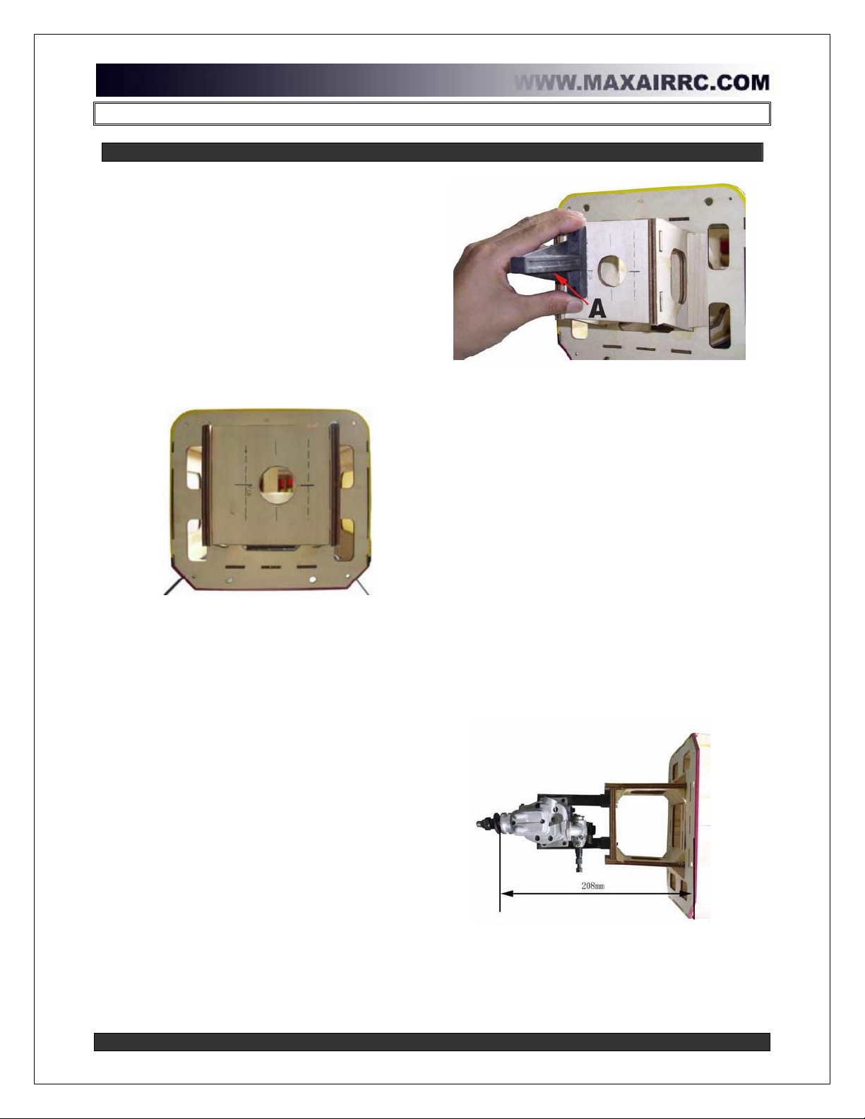
a. The center of the hole in the front of the
motor box indicates the thrust line for the
aircraft. Locate the top, bottom and
each side of the hole as shown in the
picture below.
Locate thrust line based on hole center
b. Once you have marked the center of the
hole as indicated, mark the distance for
the engine mount holes. This distance
will vary depending on the width of the
engine you choose. See picture above.
c. Now that your motor box is marked as
described, you need to locate the engine
mount holes.
d. Place one side of the engine mount on
the engine mount line you just drew on
the motor box. The surface of the
engine mount that the motor will sit on, in
this case it’s the bottom since it’s an
inverted installation, needs to line up
perfectly with the horizontal mark from
the center hole, Confused yet? Look at
the picture below. In this case, the
surface ‘A’ needs to be aligned with the
aircraft thrust line.
Align the engine mount surface with the aircraft thrust line
e. Now that the engine mount has been
properly located, mark the engine mount
holes.
f. Check the alignment of the engine with the
cowl to make sure the engine is properly
aligned.
g. When satisfied, drill and mount the engine
mount.
h. The next step is to locate the engine on the
mount and adjust it so that it will be set at the
proper distance from the firewall so that the
engine is sitting in the proper position in
relation to the cowl.
i. Sit the engine on the mount and measure
208mm (8.2in) from the firewall to the front of
the engine’s propeller hub.
j. Test fit the cowl at this position. If you are
happy with this position, mark the engine
mount holes, drill the engine mount and
secure the engine to the mount.
Proper engine position from the firewall (208mm / 8.2in)
Continued…
www.maxairrc.com Page 17 of 19
Step 14 (continued…) – Mount the engine
The next step to complete the engine
installation is to mount the throttle servo.
The Velox Revolution II was designed to allow
for the throttle servo to be mounted on the right
or left hand side of the fuselage.
k. Place the throttle servo in the throttle
servo mount on the side of the fuselage
where the throttle assembly on your
engine is located.
l. Align the throttle so that the control rod
to the engine is able to move freely with
no binding.
m. Mark the holes and drill with a 1.5mm drill
bit. Drip some thin CA in the holes to
strengthen the hole.
n. When the CA has dried screw the throttle
servo to the mount and finish installing the
throttle control rod.
Install the throttle servo
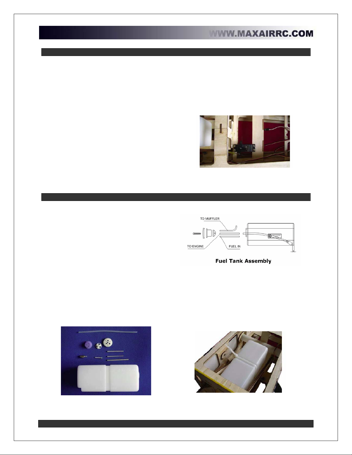
Step 15 - Assemble and mount the fuel tank
a. The first step in assembling the fuel tank
is to slide plastic cover onto the supplied
screw. The slide the rubber stopper onto
the screw and sandwich the rubber
stopper with the metal base plate.
Screw the assembly together, but do not
tighten yet.
b. Slide the copper tubes into the stopper
assembly. You may use a 2 or 3 line
setup as per your needs.
c. Make sure that the vent tube is bent
upwards into the tank.
d. Slide the silicone fuel tubing onto the fuel
feed tube. Place the clunk on the other
end of the silicone fuel tubing and make
sure the length of the silicone tubing
allows it to move freely in the tank when
assembled.
Fuel tank components
e. Insert the stopper assembly in the tank and
tighten the screw to seal the tank.
f. Once the tank is assembled, place the fuel
tank on the fuel tank shelf in the front of the
fuselage as show below. Place some foam
rubber under the tank and secure to the
shelf. We like to use zip ties to secure the
tank.
Fuel tank secured to the fuselage

www.maxairrc.com Page 18 of 19
Step 16 - Final Assembly
Belly pan
a. Replace the belly pan and screw into
place. Use a little bit of removable
thread locking compound on the screws.
Replace the belly pan
Fasten the belly pan with included screws
Prepare fuselage wing holes
b. Remove the covering from the holes on
the side of the fuselage where the wing
tube, wing support nylon bolts and servo
extension pass through. It’s always a
good idea to iron down the covering
once the hole has been cut.
c. Slide the wing tube onto the fuselage.
d. Remove the wingnuts from the wing
nylon support bolts and trial fit the wing
on the plane.
Trial fit the wings
Prepare the canopy/hatch hold downs
e. Place the top hatch on the fuselage. Find
the screw holes on the side of the fuselage.
There are two on each side.
f. Cut the covering off of the screw holes.
g. Drill the top hatch support tab through the
screw hole to ensure perfect alignment.
h. Once drilled, drip some thin CA into the
screw holes in the side of the fuselage as
well as the ones on the top hatch support
tabs to strengthen them.
Mark and drill a 2mm hole for the
Strengthen the holes with thin ca
Be careful not to drip any CA onto the covering.
i. Fix the top hatch to the fuselage using M2.5
x 8 self-tapping screws.
Fix the top hatch to the fuselage
Continued…
www.maxairrc.com Page 19 of 19
Step 16 (Continued…) - Final Assembly
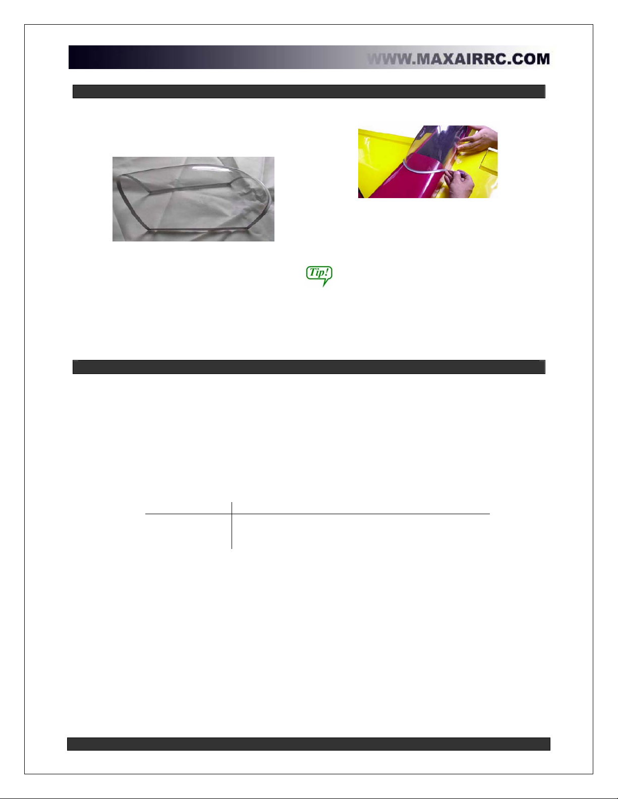
Attach the canopy
j. Prepare the canopy as illustrated below.
Test fit the canopy before cutting.
Prepare the canopy for installation
k. Place the canopy on the fuselage and
temporarily hold down with tape. Once
satisfied with the position, mark and drill
the pilot holes for the screws that will
hold down the canopy.
Mark and drill pilot holes
l. Drip some CA into the pilot holes to
strengthen.
m. Once dry, attach the canopy with the
included screws.
Canopy glue can be used to help strengthen
the canopy installation, but this makes it a
permanent installation.
Step 17 Final adjustments
Your MAXAIR Velox Revolution II is almost ready to fly. A few more adjustments and a final
pre-flight check and you’re ready to go!
-Center of Gravity: A good starting point for the balance of the plane is 145mm (5.7in)
from the leading edge at the root of the wing.
-Lateral balance: Do not forget to balance your model laterally (side to side). This is very
important.
-Control throws: Adjust your control thrown as per the table below:
Recommended Control Throws
Low rates High rates
Rudder 20º 35º
Aileron 15º 25º
Elevator 15º 40º
-Surface Deflection: The elevator uses split surfaces. It is very important that each half
moves the same amount as the other half to fly properly. Measure and adjust the
deflection as necessary.
-Perform you final check to make sure everything is secured properly and go flying!
-After your first flight, check everything to make sure none of the screws have vibrated
loose.
Be safe and have fun!
Table of contents


