Jotika H.M.S VICTORY 1805 User manual

H.M.S VICTORY 1805
Exact scale model of the 100-Gun British Ship of the Line.
Ordered by the Navy Board on 6th June 1759, Victory was designed by Sir Thomas Slade.
Construction commenced on 23rd July 1759 under the Master Shipwright John Lock at Chatham
Dockyard. Launched on 7th May 1765 and after initial sea trials, she was laid up in ordinary for
thirteen years until France joined the War of American Independence. On 12th March 1778, Victory
received her first commission under Captain John Lindsay and so her career had begun.
Manual 1 of 3
Hull Construction
Additional photos of every stage of construction can be found on our website at:
http://www.jotika-ltd.com
Nelsons Navy Kits manufactured and distributed by JoTiKa Ltd.
Model Marine Warehouse, Hadzor, Droitwich, WR9 7DS.
Tel ~ +44 (0) 1905 776 073
Fax ~ +44 (0) 1905 776 712

©2003 JoTiKa Ltd. 1
H.M.S. VICTORY 1805
After more than two years of extensive research and development, using information and sources previously unavailable, this
is the most historically accurate, highly detailed model of Victory in her Trafalgar condition available.
Forever associated with Nelson's last battle, H.M.S. Victory is one of the most famous ships of all time, and is now preserved
as a major part of the Royal Naval Museum in Portsmouth. The ship's survival is particularly appropriate since Victory is not
only an example of the ultimate sailing warship ~ the three decker First Rate ~ but she was also the most popular and
successful 100-Gun ship of the period.
Forty years old by the time of Trafalgar (1805), she had been the flagship of half a dozen Admirals, and was to continue in
active service until 1812.
This was not the first ship of the Royal Navy to bear the name Victory; there were in fact four predecessors:
1. The first Victory was built in 1559. In 1586, she was rebuilt to 800 tons and carried 34 guns with a crew of 750. At the
defeat of the Spanish Armada in 1588, she was the flagship of Sir John Hawkins.
2. Phineas Pett designed the second Victory. She was built at Deptford and launched in 1620. Rebuilt in 1666 to 1029 tons and
carried 42 guns and a crew of 500.
3. The Royal James of 1675 was renamed the third Victory in 1691. She was rebuilt in 1695 to 1486 tons and carried 100 guns
and a crew of 754.
4. The fourth Victory suffered a tragic fate. Launched in 1737, she was of 1920 tons, carried 100 guns and had a crew of 900.
She was lost during a gale while off the Casquets in October 1744. Her whole crew perished with her ~ this tragedy caused the
name Victory to be deleted, temporarily, from the Admiralty's list of ship names.
This, the fifth Victory, was one of twelve ships ordered by the Navy Board on June 6th 1759 ~ more than 40 years before the
battle of Trafalgar for which she is famed. Designed by Sir Thomas Slade, construction began at Chatham Dockyard on July
23rd 1759, the 'marvellous year' (Annus Mirabilis). This, the year of victories, marked the turning point of the 'seven years war'
for Britain. These facts may well have played a significant part in the naming of the vessel and the name Victory being restored
to the Admiralty list of ships.
As with all of our models, Victory has been designed using the latest CAD/CAM technology. With this versatility, continual
refinements can be made to ensure the model matches the most recent research available.
Nelsons’ Prayer:
In the hours before the battle of Trafalgar, Nelson, in the Great Cabin onboard Victory composed the following prayer:
“May the Great God, whom I worship, grant to my Country and for the benefit of Europe in general, a great and glorious
victory: and may no misconduct, in any one, tarnish it: and may humanity after victory be the predominant feature in the
British Fleet.
For myself individually, I commit my life to Him who made me and may His blessing light upon my endeavours for serving
my Country faithfully. To Him I resign myself and the just cause which is entrusted to me to defend.
Amen, Amen, Amen.”
At approximately 13:15 this same day, Nelson was struck by a musket shot fired from the French Ship Redoubtable. As Nelson
died some three hours later he was heard to say:
“Thank God, I have done my duty.”

©2003 JoTiKa Ltd.
2
Getting started
Victory is an exact scale model designed using original Admiralty plans. All fittings, masts and rigging have been researched
using contemporary sources and the most up to date reference material available.
Although the kit is as prefabricated as we can make it, basic woodworking skills are required. Estimated build time is between
2400 to 3000 hours, so a work space will have to be put aside for the job. Do not remove parts from the CNC cut sheets until
actually required.
Carefully study the plans in conjunction with the instructions until you are confident to tackle each stage of construction.
Patience is the key word when building any model. Treat each stage as a separate project and the overall effect of the
completed subject will be enhanced.
Recommended Tool List
1: Craft knife
2: A selection of needle files
3: Razor saw
4: Small wood plane
5: Pin vice or small electric drill (the latter is the more recommended item)
6: Selection of drill bitts from 0.5mm to 3mm
7: Selection of abrasive paper and sanding block
8: Selection of good quality paint brushes
9: Long nose pliers and wire cutters
10: Good quality tweezers
11: Dividers or compass
12: Steel rule (300mm)
13: Clothes pegs or crocodile clips
14: Tee-Square
15: Good quality pencil or Edding pen
16: Masking tape
Paints, stains and adhesives
1: White PVA wood glue
2: Walnut wood dye (for masts)
3: Cyanoacrylate (super glue) thick and medium viscosity (Admiralty Glues, Thick (AG9103) & Medium (AG9102))
4: Walnut wood filler
5: White spirit
6: Matt polyurethane varnish (not satin or gloss)
7: Black paint for ‘woodwork’ (Admiralty Paints: Dull Black, AP9105)
8: Black paint for ‘ironwork’ (Admiralty Paints: Matt (Metal) Black, AP9106)
9: White paint (Admiralty Paints: Matt White, AP9111)
10: French blue paint (Admiralty Paints: French Blue, AP9117)
11: Yellow ochre paint (Admiralty Paints: Yellow Ochre, AP9115)
12: Red ochre paint (Admiralty Paints: Red Ochre, AP9116)
13: Copper paint (Admiralty Paints: Copper, AP9126)
14: Gold paint (Admiralty Paints: Gold/Brass, AP9125)
15: Brown (wood/leather) paint (Admiralty Paints: Wood (Walnut) Brown, AP9119)
16: Olive green paint (Admiralty Paints: Olive Green, AP9118)
We highly recommend the use of Admiralty Paints; this is a new brand of paint which contains a specific range for 17th / 18th
/ 19th Century Man of War colours. This range of scale paints has been colour matched to the Admiralty colours, as still used
on HMS Victory in Portsmouth. Unlike other manufacturers, these are not toy paints and have been designed specifically for
use on model ships to give consistent coverage and colour. In order to achieve this, they may contain lead / lead chromate and
as such should not be used on children’s toys or surfaces that may be chewed.

©2003 JoTiKa Ltd. 3
Before You Begin.
Before you start building this model a little forethought now will be well worth the time given to it throughout the building
process.
Although the majority of suggestions will be second nature to the more experienced modeller, this kit and others in the series
can be built by the less experienced, given sufficient information.
The instructions and parts manual has been compiled to give as much information as practicable together with additional
diagrams, photos and a complete set of actual scale technical plans.
Wherever possible we have tried to explain technical terms, in particular nautical terminology but it pays to have a good
selection of reference books to hand.
Despite the 1:72 scale of the model, the overall size of the model is rather large. You should consider this when setting aside a
work area for the build. You will also need regular access to both sides of the model, especially when rigging, you will
therefore need an area large enough to walk around the model or large enough to easily turn the model through 180 degrees
without risking damage. Also ensure the cords for any power tools will not interfere with the model.
A 5mm ply stand is provided with the kit. This will primarily be used to support the hull during build process. Ideally this
stand should be secured to an adequate baseboard. Upon completion, the model can be placed on a display stand of your
choice.
During the build it will be necessary to sand down large areas, (after the first and second planking and at other stages) it is
therefore advisable to work in a well ventilated area and / or wear appropriate protection. The same applies when using paints,
stains, glues, fillers etc. Good lighting is also essential to the modelmaker.
The structural parts of the model are cut from high quality birch plywood, the remaining wood parts are cut from high quality
walnut ply and walnut.
Take particular care when removing parts with a craft knife and ensure all parts are identified and marked with pencil before
removal. Lay the sheet from which you are going to cut the parts on a rigid flat cutting board for removal. Use a heavy-duty
craft knife with a good strong blade to cut through the tabs holding the parts in place. It will also be an advantage to paint the
brass etched fittings prior to removal from the sheet, they can then be touched up again when in place. Alternatively when
cutting brass or copper parts, a good pair of stout scissors will suffice.
Before each stage of construction, study both the manual and the plans until you are confident in the task ahead.
The majority of the model will be painted during various stages of the build. It is important to think ahead to the next stage in
the construction process and paint the various parts at a convenient time, usually before securing on the model. It is often a
good idea to paint parts for the next stage and while they are drying you can be working on the current stage.
Wherever possible, offer the parts together in a ‘dry’ fit before final assembly.
Before Planking The Hull ~ A Note
In order that the final width of the planked hull will match the width of the stern post, some sanding will be required prior to
both first and second planking.
Before the first planking is applied as described on page 6:
1. Using Plan Sheet 2 for reference, mark the bearding line onto the keel.
2. Gently sand the shaded area, sternwards, until you have a taper that runs from 5mm wide at the bearding line to 2mm
wide at the stern.
3. Continue as instructed with the first planking and upon completion the width at the stern will be 5mm.
Before the second planking is applied as described on page 9:
1. Note the bearding line onto the first planking, again using Plan Sheet 2 for reference.
2. Gently sand the shaded area, sternwards, until you have a taper from the bearding line to 3mm wide at the stern.
3. Continue as instructed with the second planking and upon completion the width at the stern will again be 5mm.

©2003 JoTiKa Ltd.
4
Hull Construction
Cut out the main keel (19) from the 5mm ply sheet, together with the 5mm walnut pieces; stem (55), front keelson (56).
Glue the walnut pieces into position along the ply keel edges using PVA wood glue. Tape can also be used to assist. Make sure
that the structure remains perfectly flat, straight and in line whilst drying.
A suitable building board should be considered at this point. Construct the board from MDF or similar sturdy material. The
board should be long enough and wide enough to protect the hull throughout construction.
After numbering all the parts of the 5mm ply sheet, remove all the bulkheads (1-18), the middle gun deck (22) and the plank
termination patterns (20 & 21). Using Plan Sheet 1 for reference, dry fit the bulkheads and middle gun deck into position and
make sure that the whole assembly is square.
Remove bulkhead (1) and put it to one side, it will be fitted in the next building sequence.
If you are happy with the remaining bulkheads they can now be fitted and glued into position with PVA, together with the
middle gun deck.
Supplied with the kit in 5mm ply are four dummy barrel strips (39). These strips will be used as fixing points for the 32
pounders on the lower gun deck and the 28 pounders on the middle gun deck. These strips will be inserted into the slots in the
bulkheads running fore and aft throughout bulkheads (2) to (17).
When the keel and bulkhead assembly has dried to a rigid form, you will notice the slots in the bulkheads and the slight curve
to which they run. In order to insert the dummy barrel strips they will either have to be warmed with a heat gun or soaked in
water for a short time, only a slight curve in necessary!
Push these strips into the bulkheads (2 - 17), from the front. Once inserted they should be as far forward as possible while still
allowing bulkhead 1 to be positioned, they can now be secured. Once the structure has dried thoroughly, remove any excess of
the barrel strips behind bulkhead 17.
Bulkhead (1) can now be glued into position.
When this part of the construction has completely dried, it will be necessary to remove a small section of the uppermost
dummy barrel strip between bulkheads (9) and (10) on both sides of the hull to allow for the positioning of the side entry ports,
port and starboard (Photo 001).
Glue the bow forward supports (40 – 42) into position on bulkhead 1, then glue the plank termination patterns (20 & 21) into
position. Also glue the stern extensions (105 & 106) into position on bulkhead 18, as shown on Plan Sheet 1, care should be
taken to ensure they remain square to bulkhead 18.
At this stage, consideration should be given to how the finished model is to be displayed. It is recommended that using a 3mm
drill, drill 3 holes up into the keel one in the centre and one in each end at an even distance apart. Upon completion of the
model, three brass or stainless steel rods can be used to support the model on your chosen display board.
Photo 001
Photo 002
Now the 1.5mm ply gunport patterns (270, 271, 272, 276) can be fitted.
There are a number of important points to consider at this stage and they are as follows:
1. Care should be exercised to ensure the gunport patterns are fitted correctly because, at a later stage, the gunports must
correspond with the gunports in the upper gun deck, quarterdeck and forecastle inner bulwark gunport patterns (273, 274,
275, 276).
2. Make sure that the openings have been cleared of any debris. It will also be an advantage if the openings are made square
in the corners to greatly assist you when the gunport linings are fitted.
3. Make full use of glues and pins to secure the patterns, even though some of the bulkhead top sections will be removed
during later building stages.

©2003 JoTiKa Ltd. 5
Temporarily pin the quarterdeck (446) in place.
Starting with the top gunport pattern (270), position the pattern so that:
1. The back edge is flush with the outer stern extension pattern (106), (Photo 002).
2. The rearmost upper gun deck gunport back edge is flush with the front of bulkhead 17.
3. Make sure that the top edge of the gunport pattern lies 1mm above the ply quarterdeck (446) between bulkheads 6 &
9, this will allow the deck planking to sit flush with the pattern at a later stage, (Photo 003).
4. Photo 003
Photo 004
Once that you are happy with the positioning, pin and glue into place, remove any excess from the front of the pattern so that it
is flush with the front of bulkhead 1. Repeat the procedure with the opposite pattern.
Glue and pin the patterns alternatively left and right throughout the building stage.
If building to the Trafalgar condition, the outer forecastle gunport strip (276) should now be fitted so that the rearmost edge sits
flush with the raised lip of the top gunport pattern (270). (If you have decided to build to the Portsmouth (2003) specification
this pattern (276) should be emitted.)
Note: The forward edge does not sit flush with the forward edge of bulkhead 1, (Photo 004). You will also notice that the
bulkhead tops foul the gunports, do not worry as they are removed at a later stage.
The middle gunport pattern (271) can now be offered into position directly under (270), (Photo 005).
However, this pattern will fit around the bow and fit flush against the stem. In order to achieve this, the pattern will have to be
soaked in water. It will also be necessary to bevel the edges of the plank termination patterns (20 & 21), the bow forward
supports (40 - 42) and also bulkheads (1 & 2). Pin and glue as necessary.
The lower gunport pattern (272) can now be fitted in a similar manner. The leading edges of the forward bulkheads will require
bevelling and the pattern will have to be soaked in water.
Refer to the drawings and make sure that the rear part of pattern (270) and (272) run in a uniform manner (Photo 006), any
excess material should be removed from the front edge.
Photo 005
Photo 006
The quarterdeck (446) can now be removed and the whole assembly set aside to dry thoroughly.

©2003 JoTiKa Ltd.
6
First Planking
Before the first planking begins, it will be necessary to bevel the edges and undersides of the bulkheads at the bow and at the
stern. Bulkhead (18) will need to be bevelled along its underside to quite an angle, (Photo 007).
Also, taper the keel as previously instructed on page 3.
With the side patterns in position and thoroughly dry, now is the best time to bevel the bulkheads, as the structure is very rigid
and sturdy.
Place a single piece of 1.5x6mm limewood across the bulkheads and you will see quite clearly where the bevelling is required.
After bevelling, the first planking can be applied using 1.5x6mm limewood strip.
The first plank is laid directly against the lower edge of the lower gunport pattern (272). As the plywood bulkheads are very
strong, it is recommended that 0.5mm holes be drilled into the bulkheads before the insertion of the pins. When pushing the
brass pins into the planks and bulkheads, leave at least 3mm protruding so that they can be easily removed once the planks are
secure, (Photo 007) Glue the planks into position using PVA wood glue. Ensure that you glue every area of contact with the
planks and bulkheads.
The first ten planks on each side are relatively straight forward, as they require little or no tapering. As you start down to the
curved side of the bow, the planks will need to be tapered to follow the natural run of the planks. In order to determine the
amount of taper required for each plank to lie naturally, lay the plank from the 6th bulkhead around to the bow, mark the
excess area of the plank that overlaps the plank immediately above it. Repeat this process for the stern also.
Before cutting the taper into the planks, soak them in warm water for an hour or so as this will minimise the chance of the
knife blade following the grain of the wood rather than the edge of the steel rule.
Lay the first wet plank to be tapered on a clean, flat surface (a cutting mat is ideal). Press firmly with a steel rule onto the
marked taper line on the plank and score down the line with a heavy-duty craft knife several times until the excess is cut off
(do not attempt to cut the plank in one pass!).
Pin and glue the tapered planks into position on the hull leaving a little excess across the bottom edge of bulkhead (18) which
can be trimmed to shape once the planking is complete, (Photo 007).
Glue two or three planks alternatively each side, this method should prevent any possible warping or twisting of the bulkheads
and keel.
Use this planking method right down the hull. When planking is almost complete you will notice triangular shaped gaps at the
stern (and bow to a lesser degree). This was also the case in full size practise, although not so simplified. The use of triangular
shaped planks (called stealers) is needed for these gaps. Cut these to shape using the excess limewood from the ends of the
planking and glue them into the gaps.
Trim the excess stern planks at bulkhead (18) to shape and leave the hull to fully cure for at least 24 hours.
The next stage is to sand the hull with a coarse grade abrasive paper, followed by a medium grade. This will obviously entail a
few hours work but it will form the basis for the second planking, remember to remove all pins before sanding begins.
The building cradle (43, 44 & 45) can now be constructed and secured to the building board of your choice.
Photo 007

©2003 JoTiKa Ltd. 7
Quarter Galleries
Refer to (Fig 001) for the correct assembly of the quarter galleries. Time patience and care will be required during this stage of
construction but you will be greatly rewarded by the end product.
During this stage of construction, it will be necessary to glaze the quarter pattern skins (365, 367, & 369) before they are glued
into position. Should these skins require any filing or sanding then it should be done prior to glazing.
Cut out the main quarter gallery inside pattern (373) from the 1.5mm walnut sheet together with the stern fascia inner skin
(374) and upper stern counter pattern (371).
Identify, label and remove all the quarter gallery patterns from the 2mm walnut sheet.
Temporarily pin the inner stern fascia pattern (374) centrally across the stern extensions. The lower edge of the fascia pattern
should follow the angles of the stern extensions, (Fig 002).
Insert into the side slots of (374) the top quarter gallery pattern (215) and at the same time fit this top pattern (215) into the
pattern (373).
The main quarter gallery inside pattern (373) should now locate into the two slots in the top gunport pattern (270), at the same
time the downward and outward angle of the top quarter gallery pattern (215) should be maintained, (Photo 008).
Fig 001
Photo 008
Photo 009

©2003 JoTiKa Ltd.
8
Fig 002
This building stage may appear to be more complicated than it really is, there is a need for several pieces of the structure to fit
together at the same time. However, with a little patience, thought and care it will all come together.
Check the pieces fit first, re-check and check again!
When you are completely satisfied with the fit and building process then the main quarter gallery inside pattern (373) can be
glued into position.
The stern fascia inner skin (374) can also be glued into position. If it is decided to use pins, take care not to distort the fascia’s
natural curve across the stern extensions.
Once these pieces have been glued into position, the remaining quarter gallery patterns (215-219) can also be glued in place.
Work alternatively each side maintaining the correct downward angle.
You will notice that there are two patterns (219) each side. They are the same size and one fits into the full slot and the other
into the half slot on the bottom edge of the stern fascia (374). Glue both patterns into place.
From the 1.5mm walnut sheet remove the upper stern counter pattern (371) and offer its top edge to the bottom edge of the
stern fascia (374). These two edges are to butt up against each other and slight bevelling will be required, (Fig 002).
Glue the counter pattern (371) into position.
The 7th quarter gallery pattern (220) can now be glued into position and its bottom edge should sit flush with the bottom edge
of the upper stern counter pattern (371).
From the 1.5mm walnut sheet remove the lower stern counter pattern (372). This pattern can be fitted and glued into position
in a similar manner. However, it will have to be soaked in water first but only for a short period – bear in mind that the ply
wood is held together by a water soluble glue!
When you are able to offer this pattern (372) into position the top edge will also require bevelling. You will also be in a
position to see how much of the first planking may need be to be sanded from the lower edge of bulkhead 18 to ensure a good
fit in preparation for the second planking. With the lower stern counter pattern in place, you can attach the brass etched double
door vent hinges as shown (Fig 003), and painted black.
Fig 003
Note upper tab orientation489

©2003 JoTiKa Ltd. 9
Once this stage has been completed, it will become obvious that the 1.5mm walnut quarter gallery skins (365-370) will join
along these patterns, you will also notice the downward and outward lie of these skins. N.B. All trimming of these skins
should be made along the foremost edge, do not trim the rear edge that sits flush against the stern fascia (374)!
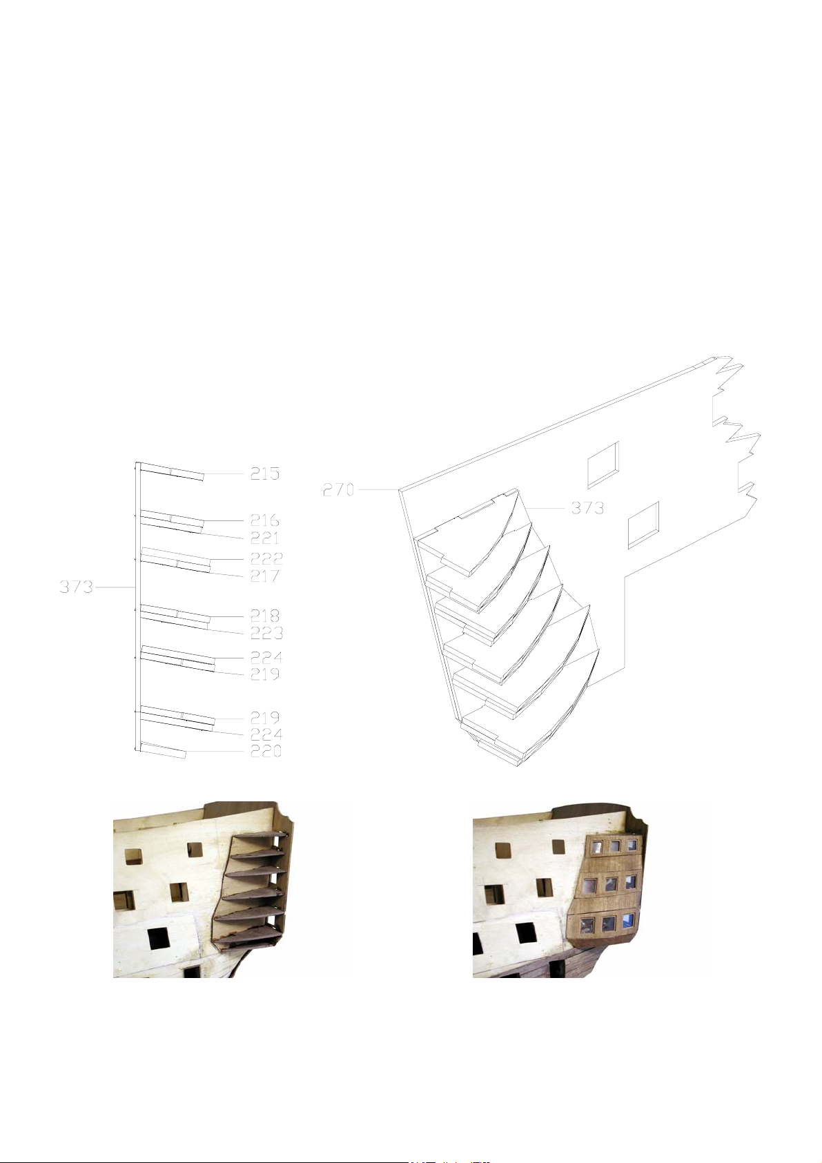
The 2mm walnut quarter gallery insert patterns (221-224) can now be glued into position (Fig 001). They will require
bevelling to form the basic shape, it is advisable to check the skins against their respective locations as you progress down the
galleries. Again work on alternating sides.
Before the quarter gallery skins with windows (365, 367 & 369) are glued into position, it is advisable to clean out the corners
of the recess in preparation of fitting the window frames, also they will have to be glazed with the plastic glazing provided.
Glue the sheet to the inside of the skin to cover the three openings. Use PVA to do this as the fumes from super glue will
discolour and cloud the glazing, (Photo 009).
In conjunction with the drawings provided, work down the skins fitting and gluing into position. Bevelling and shaping will be
required.
Take extra care not to damage the glazing on the skins.
The stern fascia will be glazed at a later time between the inner and outer patterns.
Middle Gun Deck Planking
A small area of this gun deck will be visible through the upper gun deck companionways and the side entry ports. Using
1x4mm Tanganyika, plank the middle gun deck between bulkheads (4) and (12) and across the beam to the bulkhead risers and
plank completely across the beam at the side entry ports position. Make sure the main mast hole is cleared. Glue into position
the main mast sleeves (154), the mast sleeves will requiring filing to allow the main mast to pass through at the correct angle
(as determined by the slot in the keel).
When planked, lightly sand the deck smooth. Apply a coat or two of matt polyurethane varnish to seal the grain.
It is advisable at this stage to paint the areas between the outside faces of the dummy barrel strip and the deck area up to the
inner side of the ships sides. These areas will be visible to some degree and painting is better achieved at this stage, paint the
areas matt black (Humbrol 85).
Using 1x16mm walnut strip, line the entry ports.
Cut the strips to length and glue on the vertical sides first, followed by the top and bottom sills. When complete, sand the outer
sills flush with the side of the hull. If necessary, a smear of super glue over the strip, prior to cutting, can be used to avoid
splitting.
Second Planking
The second planking is laid using 1x5mm walnut. The gluing of the second planking also differs from the first as the whole
under surface of the walnut strip is glued to the surface of the first planking as well as edge to edge.
Before progressing, taper the first planking as previously instructed on page 3.
Referring to Plan Sheet 2, mark the position of the upper edge of the middle wale onto the hull, this is best achieved by
measuring the distance from each gunport lower edge to the point of intersection with the wale and joining these points with a
smooth line (formed by temporarily positioning a plank against the hull). This line now denotes the upper edge of the first
plank, of the second planking, which can now be laid.
Once the first walnut strip has been laid, work down to the keel using the same planking method as the first planking. Some
slight tapering will be required at the bows and it should be treated in a similar manner to the first planking method. The
walnut planking around the bows will have to be soaked in water first.
The best glue to use above the waterline is medium super glue. This is to avoid the use of pins, eliminating pinholes that would
have to be filled prior to painting. Super glue will stick the planks as well, if not better than, PVA wood glue. Around the bow
area, where the walnut strip has been soaked in water, take extra care – wet wood and super glue will bond more or less
instantly! Great care is needed to attain as neat a job as possible to minimise the need for filling. If desired, PVA wood glue
can be used for the planking beneath the waterline in conjunction with pins temporarily pushed half way in, until the glue has
cured.
After the lower planking has been laid, identify and fit the back keelson (57) and stern post (58).
Note: Lay one or two planks on alternative sides when planking, to avoid ‘pulling’ the keel out of shape, cutting the gunport
openings as you progress: cut the gunports to exactly the same size as the gunport patterns.
Note: With the lower planking completed, you can continue to plank upwards but at this stage do not plank over any of the
gunport openings of the upper deck! This area will be planked at a later stage because eight of the centre gunports have to be
lined first and this cannot be done until the upper deck inner bulwark pattern (275) has been fitted.

©2003 JoTiKa Ltd.
10
The Upper Gun Deck
Work can now commence on the upper gun deck. It is necessary to suspend work on the remainder of the uppermost area of
the hull planking until this deck is almost completed. It is the easiest option and the way in which the prototype was
constructed.
From the 5mm ply sheet identify, label and remove the upper deck camber beams (26, 28, 29, 30, 31 & 32). These beams
correspond to the bulkheads as identified in the cutting list. Remove the upper gun deck (445) from the 0.8mm ply sheet.
Remove both of the upper gun deck inner bulwark gunport patterns (275) from the 1.5mm ply sheet.
Locate, fit and glue into position the upper gun deck camber beams as identified earlier, referring to Plan Sheet 1 noting the
location of the camber beams either in front of, or behind the bulkheads. When dry, the upper gun deck (445) can be fitted.
Locate and fit the deck into position on the beams so that it lies perfectly flat and even both across the beams and fore and aft.
Some slight shaping may be required along the outside edges and in the slots, the deck must fit neatly. Before the deck is glued
into position, offer into place the inner bulwark pattern (275) making sure the inner and outer gunport openings are aligned:
back, front, top & bottom. The pattern (275) has been designed to allow some lateral movement.
When completely satisfied with the fit, glue the deck into position, making sure the mast holes (cut outs) align to the deck
below and the angled slots in the keel.
Once the deck has dried and having regard to the foregoing instructions fit and glue into position the upper gun deck inner
bulwark patterns (275).
Planking the Upper Gun Deck
The beakhead bulkhead (205) will be fitted at a later stage across bulkhead (1). Offer the bulkhead (205) into position, on the
front of bulkhead (1), and mark a line in pencil across the ply deck behind the bulkhead (205). This pencil line is where the
planking will terminate. Now mark a centre line down the ply deck.
Using 1x4mm Tanganyika strip, plank from the centre line alternatively across the deck to each inner bulwark, clearing all
hatches, companionways and mast holes as you progress.
Note: If you wish to accurately represent the plank length and four butt shift system used on Victory, each plank should be
either cut to a length of 85mm (approximately 20ft) or the planks can be laid full length and scored with a craft knife every
85mm, this latter method often looks the most convincing at this scale. The four butt shift system simply implies that the end
of each neighbouring plank is offset by 1/5 of twice the length of the planks (34mm) such that the end of every fifth plank
athwartships only is aligned (i.e. separated by a four plank shift).
Once completed, lightly sand the deck smooth and apply several coats of matt polyurethane varnish.
Glue into position the mast coats (155 & 157), make sure the mast holes are cleared, the mast sleeves will requiring filing to
allow the mast to pass through at the correct angle (as determined by the slots in the keel). The mast coats should be varnished.
Before the inner bulwarks of the upper gun deck can be planked, several gunports will have to be lined.
The only gunports that need to be lined at this stage are those without gunport lids. Referring to Plan Sheet 2, you will notice
that the 3rd to the 10th gunports inclusive do not have lids. Using 1x16mm walnut strip, cut to length and glue on the vertical
sides followed by the top and bottom sills. When complete, sand the inner and outer sills flush with the side of the hull and
inner bulwark patterns. If necessary, a smear of super glue over the strip, prior to cutting, can be used to avoid splitting.
Using 1x4mm walnut strip, plank the inner bulwark patterns (275), clearing the gunports as you progress. Refer to Plan Sheet
1, noting the location of the quarterdeck camber beams. However, do not glue them into position, merely temporarily fit them
to give you their positions whilst planking, then put them to one side.
The inner bulwarks will be painted yellow ochre (Humbrol 74).
It is now possible to resume the second outer hull planking. Continue as before using 1x5mm walnut strip and in the same
manner.
Continue planking until you reach a position over the top of the gunports you have already lined. Your last plank at this stage
should just come below the last gunport on the quarterdeck.
All work will now concentrate on the ships side.

©2003 JoTiKa Ltd. 11
The Wales
Referring to Plan Sheet 2 and (Photo 10, 11, 12 & 13) carefully mark the position of the lower wale.
Note: the wales do not follow the yellow and black bands (as described in ‘Lining the Gunports’ Page 12), but the outline of
the wales are clearly visible in the photos.
Because the positioning of all three wales are critical to maintain the natural line and aesthetics of the ships side, take your
time. As with all planking, work alternately each side, remembering where necessary to soak the planks in water.
When you are satisfied with the positioning of the lower wale, planking can begin. The uppermost plank is 0.5x4mm walnut
strip, the remaining four lower planks are 1x5mm walnut strip. Cut out the gunports as you progress, including both entry
ports.
The best glue to use for the wales is medium super glue, again this is to avoid pin holes that would need to be filled prior to
painting.
Another important point is to make sure that the top and bottom planks of each wale sit tight against the hull. At a later stage
when painting the hull, colour changes take place across the wales. The better they fit, the better the painting will be.
Continue up the ships side and apply all three wales.
The middle wale is made up of three walnut strips 1x3.5mm.
The top wale is also made up of three walnut strips 1x3.5mm.
Take extra note of the way in which the top wale, bow section, centre plank runs under the roundhouse as shown Plan Sheet 2.
The centre plank of the top wale curves around the bow and will sit approximately 1mm above the 0.8mm ply deck. When the
deck area has been planked, both the centre wale plank and the deck will be level.
Note: the top plank of this wale terminates at the beakhead bulkhead.
Photo 010
Photo 011
Photo 012
Photo 013

©2003 JoTiKa Ltd.
12
Lining the Gunports
Note: for all gunports, the linings are to be painted red ochre, it should be noted however that the gunports without lids should
have red ochre applied to the whole inner surface. For gunports with lids, the linings are painted red ochre and the 1mm deep
lip should be the colour of the surrounding ships side.
The lower and middle deck gunports can now be lined. The way in which these gunports are lined differs from those gunports
without lids. Line them with 1x6mm walnut strip in the same way as the gunports without lids except the lining must be set
back 1mm from the ships side, refer to Plan Sheet 2, ‘Gunports with lids’. It is of absolute importance that the linings are set
back into the openings by 1mm. The gunport lids themselves have been cut to allow for this and the brass etched hinges have
also been designed likewise. The hinges are glued into position onto the gunport lid and the ships side as shown on Plan Sheet
2, ‘Attaching gunport lids and hinges’. If the recessing has not been carried out correctly then the hinges will not fit.
The remaining gunports on the upper gun deck can now be lined in the same way using 1x16mm walnut strip. Once lined, cut
off any excess along the inner walls. Touch up the painting after sanding down the sills on the inboard side.
Before decking out the upper gun deck consideration should be given as to how the hull is to be painted. If the hull is to be
sprayed / air brushed for example, masking will be almost impossible when the gun carriages on this deck are in place. It is
worth considering.
The two colours used for the ships side are black and yellow ochre. The matt black is applied from the top of the copper plating
to the top of the side and is broken up by three bands of yellow ochre. Using the photos (Photo 10, 11, 12 & 13) for reference,
the following points should be taken into consideration:
1. The yellow bands do not follow the run of the gunports, neither do they correspond exactly to the wales.
2. The yellow bands vary in width throughout their length, being widest at midships and diminishing towards the bows
and transom.
3. Referring to the photographs (Photo 10, 11, 12 & 13) you can clearly see that the upper edge of each yellow band
(except that at the upper gun deck) roughly follows the top edges of the gunports, while the lower edge is well below
the ports at midship rising and reducing in width fore and aft.
The forward most gunports on the lower and middle gun decks should now be marked in position. Taking their locations from
Plan Sheet 2, mark in pencil their locations. They are then scored with a sharp craft knife, simply to represent the gunports in a
closed position. All necessary associated fittings can be applied (brass etched hinges, eyelets and rigging). Take great care not
to split the walnut planking.
Note: the middle deck gunport is a double door gunport similar to that shown (Fig 025).
The locating holes for the dummy barrels on the lower and middle gun decks can now be drilled. The spigots of both sets of
dummy barrels are 2mm. Using a slightly oversized drill, drill into the dummy barrel strip to take the barrel spigots. Ensure
that the holes are drilled horizontally so that the barrels sit about 90 degrees to the keel.
Do not glue the barrels into place at this stage. They should be painted black and their muzzle facings painted red ochre as
shown (Photo 14).
Photo 014

©2003 JoTiKa Ltd. 13
The Copper Plating
Using Plan Sheet 2 for dimensioning, mark onto the hull the waterline. Make sure the hull is completely level when marking.
When coppering, the hull will have to be laid on its side. To protect the hull lay it on some large towels or similar.
Start coppering from along the keel upwards working from stern to bow. Each line of plates should be staggered by 50% to the
plate below (similar to laying bricks) (Photo 015). To glue the plates to the hull use a medium to thick super glue. Apply a spot
of glue to the middle of the underside of the copper plate. Apply the plate to the hull using a pair of tweezers and then gently
push the plate onto the hull to spread the glue.
To cut the plates to the correct shape at the curves and when you reach the waterline, mark off onto the plate the excess area to
be cut, lay the plate on a hard flat surface and cut off the excess with a heavy-duty craft knife. Alternatively the plate can be cut
with scissors but will then need to be rolled back to flat using a small piece of softwood doweling on top of a block of flat soft
wood (Photo 016).
If on reaching the waterline you have not achieved an absolutely straight line this can easily be overcome. Apply sellotape all
around the hull just above the waterline. Press the edges down firmly to avoid any paint seepage. Using a fine brush paint the
area between the top of the copper plates and the bottom edge with copper paint. Once dry remove the sellotape for a near
perfect waterline. The underside of the keel and the end of the rudder and rudder post can either be coppered or, for ease,
copper painted.
Note: The copper plates are supplied in two bags, when you are ready to start plating it is advisable to open both bags and mix
them together. We have found that opening one bag, using these plates, then opening the second bag results in a colour
variation between the plates due to different oxidation rates.
Photo 015
Photo 016
Upper Gun Deck Fixings
Make up seven sets of grating kits from the grating strips (720) which are to be slotted together as shown (Fig 004). When
completed, brush on watered down PVA glue to secure the strips and once dry trim to fit in their respective deck openings.
The coamings on the outside of the gratings are made from 3x4mm walnut strip. The coaming should be level with the grating.
When the grating assemblies are in place, cut out and glue the shot garlands (244-251) into place as shown on Plan Sheet 3.
Fig 004

©2003 JoTiKa Ltd.
14
Fig 005
From the 2mm walnut sheet remove the upper deck main companionway shot garlands (252), the main companionway
coaming is 2x4mm walnut. With the companionway coamed, glue the shot garlands into position – this lining is intentionally
lower than the other companionway and grating linings as was the case on Victory.
Identify the companionway ladder sides (241), make three sets up using 1x5mm walnut strip for the treads. The treads should
be cut to a length 3mm less than the width of the companionway it fits into.
To assemble the ladders, slot a tread into the top and bottom of each ladder and glue into place, ideally a small jig should be
made to keep the assembly square. The remaining treads can then be pushed into the slots and brushed with watered down
PVA to seal the assembly. An upper deck stanchion (502) (painted black) should be glued directly to the front edge of each
ladder side, as shown (Fig 005) with a 0.25mm natural thread tied through the end in preparation of the companionway guard
rail assembly.
Glue the completed assemblies into position.
Carefully glue the small 12 pounder cannon balls (705) into the holes in the shot garlands using super glue and tweezers for
placement.
Paint black and fit four large cleats (660) into position on the inner bulwarks as shown on Plan Sheet 5.
Gun Carriage Assemblies
The gun barrels used in the carriage assemblies are all 12 pounders (700, 701 & 702)
The dummy barrels are either 24 pounders for the middle deck (699), or 32 pounders for the lower deck (698) and will be fitted
towards the end of construction.
This section will deal with complete gun carriage assemblies. Although all the cannons are 12 pounders, there are three
different sizes of barrel (small, medium & long) and each respective carriage differs in its assembly.
It will be an advantage to the builder to build the carriages one size at a time, as required.
For all guns, the tackles are made up of 0.1mm natural thread together with pairs of 2mm single blocks and the breaching ropes
are of 0.5mm natural thread.

©2003 JoTiKa Ltd. 15
Upper Gun Deck 30 x 12 Pounder Long Gun
Identify the 12pdr long gun brass cannon barrel (700).
When completed, the gun carriage should be painted yellow ochre. The barrel and other ironwork should be painted black and
the gun muzzle should be painted red ochre.
Make up all of the gun carriage assemblies as shown on the Plan Sheet 4, ‘Cannon carriage assemblies’. The shorter wheel
axle is located at the front to give the carriage a taper when viewed from above.
Note: do not fit the wheels until the carriage has been assembled.
The larger wheels fit on the front of the carriage to compensate for the deck camber. The wheels themselves are simply
varnished, not painted. The stub ends of each axle should be painted black.
Cut a bed bolt for each carriage from the 1mm brass wire (746) and glue into place. Glue the quoin (163) to the stool bed and
glue the stool bed into place.
Note: the stool beds for these carriages are flush with the rear of the carriage sides, the stool beds for all cannons are 0.5x3mm
walnut.
Mark the eyelet positions on each carriage and drill with a 0.5mm drill. There is also an eyelet at the centre of the rear and
front axles. Cut the stems of the brass eyelets (480) from their brass etch sheet leaving 2mm for gluing into the carriage and
glue in place.
When completed, paint the carriages as previously described. Carefully push the wheels onto the axles.
Cannon trunnions are cut from 1.5mm brass wire and should be long enough to reach the outer wall of the carriage sides. Glue
in place through the cannon and onto the carriage.
Note: check the cannon orientation beforehand, the trunnion hole is drilled slightly off centre and should be nearer the bottom
of the barrel when in place.
All cannons should be painted black and their muzzles red ochre.
Cut out the trunnion brackets (501) from their brass etched sheet. Fit by bending the thinned centre of the bracket around the
trunnion, carefully drill down through the holes in the bracket, with a 0.7mm drill, into the carriage sides. Fix in place with the
brass pins (696), these can be cut short before fixing. Paint the trunnion brackets black.
All thirty 12 pounder long guns on the upper gun deck were fully rigged on the prototype and sufficient rigging has been
provided to allow you to do the same. Using (Photo 017) for reference, if you wish to rig these guns it should be done now.
However, it must be remembered that when the quarterdeck is in place the majority of the cannons and rigging will be
inaccessible. It is important therefore, to realise that the gun carriages themselves should be secured to the deck with a small
amount of super glue.
At each gunport location, four eyelets (480) should be positioned as shown on Plan Sheet 3, ‘Eyelet arrangement for cannon
tackle’. There is also one eyelet directly behind the carriage secured to the deck as shown on Plan Sheet 3.
Once the rigging is in place, brush on watered down PVA over the ropes and blocks. Again, time effort and patience is
required for best results.
Photo 017

©2003 JoTiKa Ltd.
16
Screen to Admiral Nelson’s Quarters
From the 1.5mm walnut sheet cut out the upper deck screen bulkhead (389) and fit into place. Glue the screen to the deck and
to the front of the camber beam supports of bulkhead (13).
Directly in front of this screen, two support pillars (722) need to be fitted. The top and base of the support pillars need to be
squared off, using a sanding block, to the shape as shown (Photo 018). Any discoloration should be stained back to the original
colour. The pillars sit on the coaming of the grating as shown on Plan Sheet 5. You will need to shorten the pillar to fit, to do
this it will be necessary to remove material from both the top and bottom of the pillar.
Photo 018
1. Pillars before sanding.
2. Pillars after sanding.
3. Pillars after staining walnut.
The Main Companionway Ladder Assembly
Remove the ladder sides (242) from the 2mm walnut sheet and construct the ladder in the same manner as before to an overall
width of 24mm. There is a reason for this apparent leap in building instructions. Identify two small staircase balusters (723),
they will be used to support the handrails in the next building sequence but have to be fitted now. The top and base of the
balusters need to be squared off, using a sanding block, to the shape as shown (Photo 019). Any discoloration should be
stained back to the original colour. The main companionway ladder, when fitted, sits on the edge of the coaming of the
quarterdeck companionway, centrally. Directly in front of the ladder sides will sit the balusters to hold the ladder handrail, they
should be glued in place onto the deck now, as shown (Fig 006). The ladder itself will be fitted later.
Photo 019
1. Balusters before sanding.
2. Balusters after sanding.
3. Balusters after staining walnut.

©2003 JoTiKa Ltd. 17
Fig 006
242
723
241
Illustration of main companionway

©2003 JoTiKa Ltd.
18
Elm Tree Pump Assembly
Remove the two elm tree pump bases (85) from the 4mm walnut sheet, the elm tree pump iron top plate (497) from the brass
etched sheet, and assemble as shown on Plan Sheet 3, ‘Elm tree pump assembly’. The rod is made up from 0.7mm brass wire,
with a small loop fashioned in one end to pass through the pump handle (498). Now insert the wire into the hole in the centre
of the pump base assembly and at the same time glue the handle to the side. This whole assembly should be painted black.
Glue the assembly into position as shown on Plan Sheet 3.
The Upper Gun Deck Companionway Guard Rails
The upper gun deck stanchions (502) (painted black) can be removed from the brass etched sheet and fitted as shown (Fig
007). They fit onto the hatch coamings.
Using a 0.75mm drill, drill into the hatch coamings and secure the stanchions with super glue. The rope handrail of 0.25mm
natural thread, previously attached to the stanchions on the deck below, can now be passed up and rigged around the main
companionway sides only (Fig 007).
Note: the foremost two companionway guardrails on the upper gun deck are formed by stanchions (502) and skid beam
support pillars (722), the handrail will therefore be shipped at a later stage.
Fig 007
Steam Trunk Assembly
Identify and remove the four steam trunk sides (396) from the 1.5mm walnut sheet. Assemble the steam trunk as shown on
Plan Sheet 3, ‘Steam trunk assembly’. NB, the assembly is not square. It sits on the upper gun deck as shown on Plan Sheet 3
and under the forward hatch gratings on the forecastle and is therefore best glued into place during the quarterdeck fitting
stage.
Fig 008

©2003 JoTiKa Ltd. 19
Fitting the Quarterdeck
The ‘quarterdeck’ (446) as referred to during this stage of construction incorporates the forecastle (at the front), the
quarterdeck (at the rear) and the area in between often referred to as the waist or boat deck.
Glue (and pin as necessary) into position the quarterdeck camber beams (23 – 25, 27 & 33 – 37).
Note: their position either in front of or behind the bulkheads as shown on Plan Sheet 1, the top edge of the beams should be
level with the top edge of the bulkhead upright stubs, as shown Plan Sheet 1. Allow to dry thoroughly.
By this stage, all work on the upper gun deck should be completed (except the steam trunk, bitt pins and bitts). Check all
fixtures are secure, especially the gun carriages.
Remove the quarterdeck (446) from the 0.8m ply sheet and offer it into position. Do not glue into position. The first thing to
note is that the companionway to the Admirals dining cabin is offset, it is therefore important to fit the deck the right way up so
that the companionway is offset to port as shown on Plan Sheet 4. Make sure that the deck fits with ease, should there be no
tight spots, sand as necessary. Familiarise yourself with both fitting and removal of the deck. At this stage, note the position of
the steam trunk assembly and secure in place with super glue.
From the 1.5mm walnut sheet, remove the side linings (378) and the fore and aft linings (379) of the skid beam assembly, and
from the 5mm walnut sheet remove the skid beams (72). Glue the assembly together (Fig 008) so that it will fit into the
quarterdeck opening, the whole assembly should be painted black.
Note: two 0.7mm holes should be drilled (fore and aft) through the second from the front skid beam (33mm from the
centreline) and 0.7mm brass wire (10mm long) inserted through the holes and secured as shown. Again do not glue this
completed assembly in place.
Position the assembly into the opening and mark off where the beams lie under the ply deck. Drill into the deck using a 0.7mm
drill, also drilling part way into the under slung skid beams. Remove the skid beam assembly and put it to one side.
The quarterdeck can now be fitted. The reason for the familiarisation of the fitting of the quarterdeck is because although it is
fitted as one piece, it is done in several stages.
For the fitting of the quarterdeck, the following components will be required, the quarterdeck (446), the skid beam assembly,
the fore brace bitt pins (91 & 158), and the upper deck fore brace bitt (162).
Assemble the fore brace bitt pin assembly (using the upper deck fore brace bitt (162)) as shown (Fig 009).
Note: a hole (sheave for the fore yard brace) needs to be drilled fore to aft through the bitt pins (158) at a distance 16mm down
from the uppermost edge, the distance between the outer edges of the bitt pins should be 38mm and the quarterdeck fore brace
bitt (159) should not be used. This whole assembly should be painted black.
Using PVA and pins, locate and glue into position the quarterdeck from bulkhead (18) to bulkhead (13). It should be possible
to lift the forward end of the quarterdeck to allow the skid beam assembly and bitt pin assembly to be positioned from
underneath, do not glue them into position at this stage.
Temporarily position the skid beam assembly in the quarterdeck opening and check that the quarterdeck will still lie true to the
bulkhead camber beams with the assembly in place, sand as necessary. When you are completely satisfied with the fit, glue and
pin the skid beam assembly in place, it is essential that the assembly is permanently secured. Do not be concerned by the
excess material of the skid beam surrounds standing proud of the ply deck, this will be dealt with at a later stage.
Now, apply glue to the remainder of the bulkhead camber beams (12 to 1) and also to the base of the bitt pin assembly. The bitt
pin assembly is to be pushed up through the quarterdeck and at the same time lower the quarterdeck down into position. Make
full use of pins and glue to secure.
When thoroughly dry, the upper deck fore brace bitt pins (91) and bitt (162) can be assembled and fitted as shown on Plan
Sheet 3 & 5. Again the distance between the outer edges of the bitt pins should be 38mm. This whole assembly should be
painted black.
Fig 009
Other manuals for H.M.S VICTORY 1805
1
Table of contents
Other Jotika Toy manuals