Maxgear MAX 5073 User manual

MAX 5073
Super Bass System
INTRODUCTION
Amplifiers provide high-performance sound reinforcement for your mobile audio equipment. Its ver-
satility enables compatibility with optional Equalizers, Frequency Dividing Network Crossovers, and
other audio processors in a customized system. The Multi-Mode bridging capabilities allow flexibility
in hosting several different speaker configurations.
To achieve optimum performance. We suggest that your stereo components are installed by an aut-
horized MAXGEAR dealer. It is highly recommended that you read this Owners Manual before begin-
ning installation.
AMPLIFIER FEATURES
•SILVER RCA CONNECTORS
• DC TO DC CIRCUITRY
•POWER/PROTECTION LED
• GOLD PLATED SCREW CONNECTIONS
• THERMAL/SHORT/OVERLOAD PROTECTION CIRCUTIRY
• VARIABLE BASS BOOST (0-18Db)
•HI/LO SELECT SWITCH
•VARIABLE HPF/LPF CROSSOVER
• ADJUSTABLE INUT SENSITIVTY
• SUBSONIC FILTER 20-50HZ (V-317SX)
SUBWOOFER FEATURES
•5/8” MDF CONSTRUCTION
•HEAVY DUTY INDUSTRIAL CARPET
• HIGH POWER SUBWOOFERS
WARNING
High powered audio systems in a vehicle are capable of generating “live Concert” high levels of sound
pressure. Continued exposure to excessively high volume sound levels may cause hearing loss or
damage. Also, operation of a motor vehicle while listening to audio equipment at high volume levels
may impair your ability to hear external sounds such as; horns, warning signals, or emergency vehi-
cles, thus constituting to a potential traffic hazard.

MAX 5073
Super Bass System
MOUNTING YOUR AMPLIFIER
The mounting position of your Amplifier will have a great effect on its ability to dissipate the heat
generated during normal operation. It has an ample heat sink for heat dissipation, and is also design-
ed with a thermal shut-down protection circuit, making it reasonably tolerant of mounting variations.
Any configuration which allows moving air to be directed over the cooling fins will improve heat dis-
sipation dramatically. DO NOT enclose the amplifier in a small box or cover it so that air cannot flow
around the heat sink fins.
Temperatures in car trunks have been measured as high as 175 F (80 C) in the summer time. Since
the thermal shut-down point for the Amplifier is 185 F (85 C), it is easy to see that it must be moun-
ted for maximum cooling capability. To achieve maximum advantage of convection air flow in an
enclosed trunk, mount the amplifier in a vertical position, on a vertical surface.
Cooling requirements are considerably relaxed when mounting inside the passenger compartment
since the driver will not often allow temperatures to reach a critical point. Floor mounting under the
seat is usually satisfactory as long as there is at least 1 inch (2,5cm) above the Amplifier’s fins for
ventilation.
a. Select a suitable location that is convenient for mounting, is accessible for wiring, and has ample
room for air circulation and cooling.
b. Use the amplifier as a template to mark the mounting holes. Remove the Amplifier and drill 6 holes.
USE EXTREME CAUTION, INSPECT UNDERNEATH SURFACE BEFORE DRILLING.
c. Secure the Amplifier using the screws provided.
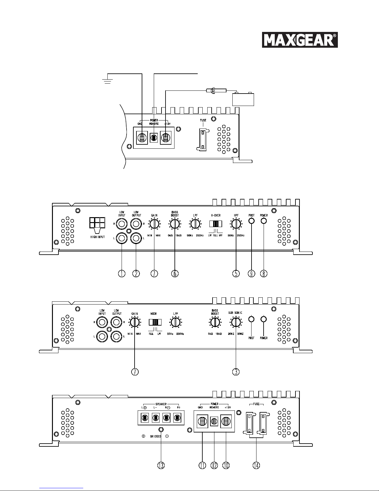
CONNECTING THE POWER
CAUTION! AS A PRECAUTION. IT IS ADVISABLE TO DISCONNECT THE VEHICLE’S BATTERY BEFORE
MAKING CONNCETIONG TO THE+12 VOLT SUPPLY WIRING.
10 GAUGE (or a large gauge of wire if planning for additional Amplifiers) wire is recommend the power
and ground wires. 20 Gauge, for the remote turn-on wire. Both types are available at most Mobile
Audio Dealers or installation Shops.
GROUND To Vehicle Chassis
Toavoid unwanted ignition noise caused by ground loops, it is essential that the Amplifier be groun-
ded to a clean, bare, metal surface of the vehicle’s chassis.
NOTE: GROUND WIRE SHOULD NOT BE EXTENDED MORE THAN 3 FT.(1 METER)
USING THIS METHOD CAN CAUSE TURN ON AND TRUN OFF TRANSIENTS (NOISE)
+12 Volt (Fused)Constant Power: To Battery (+)
Due to the power requirements of the Amplifier, this connection should be made directly to the posi-
tive (+) terminal of battery. For safety measures, install an in-line 50 Amp Fuse Holder(not
included)as close to the battery positive (+) terminal as possible, with an ampere rating not to exceed
the total value of fuses in amp.
Remote Turn-On Input: To Power Antenna output of Car Stereo
This Amplifier is turned “ON” remotely when the vehicle’s stereo is turned “ON”.
NOTE: IF YOUR RADIO DOES NOT HAVE A +12 VOLT OUTPUT LEAD WHEN THE RADIO IS TURNED
ON, “RMT” TERMINAL ON THE AMPLIFIER CAN BE CONNECTED TO VEHICLE’S ACCESSORY CIRCUIT
THAT IS LIVE WHEN THE KEY IS “ON”.

MAX 5073
Super Bass System
FEATURES & CONTROL
Remote Tun ON
TO Power Antenna
BATTERY
FUSE Holder
Near Battery
Ground
Chassis -!
Ground
Chassis

MAX 5073
Super Bass System
FEATURES&CONTROL
(1)RCA Line Input Jacks
To be connected to a line driver, crossover or head unit via RCA Cables.
(2)RCA Line Output Jacks
For connecting additional amplifiers for additional speakers.
(3)24dB Subsonic Filter Control
Permits a 24dB per octave high pass filter between 20-50Hz
(4)24dB Low Pass Variable Control
Adjustable low pass crossover frequency from 50Hz-250Hz
(5)24dB High Pass Variable Control
Adjustable high pass crossover frequency from 50Hz-250Hz
(6)0-18dB Bass Boost Control
The Bass Boost Control is used for a 0-18dB gain at 45Hz for extra bass punch.
(7)Input Gain Level Control
For adjusting the output of the amplifier to the input of the source unit. Adjustment range is from
0.2V to 8.0V.
(8)Power LED
The Blue color LED indicates that the power is on.
(9)Protection LED
The Red color LED indicates fault condition of amplifier.
When a fault condition occurs such as an overload, excessive heat or short circuit of speaker
terminals, the protection circuit is engaged to protect both the subwoofers and amplifier.
(10)Power Connection
Connect +12V DC power wire from battery source to amplifier.
(11)Ground Connection
Connects the Ground wire of amplifier to the chassis ground.
(12)Remote Connection
Connects the remote wire allowing the amplifier to be turned on/off by the head unit.
(13)Speaker Terminal
It allows the connection of a speaker to the amplifier.
(14)Fuse
Power protection for the amplifier.
HIGH/LOW PASS VARIABLE CROSSOVERS (50HZ-250HZ)
a) For use as a dedicated subwoofer channel(front or rear),select Lo pass switch. This activates the
low pass filter circuitry.
b) For us as a mid to hi range channel(front or rear),select Hi pass switch. This activates the hi pass
filter circuitry.
c) For normal full-range amplifier use, set to “FULL”.

MAX 5073
Super Bass System
CONNECTING HIGH LEVEL INPUTS
NOTE: DO NOT CONNECT THESE HIGH LEVEL INPUT WIRES IF YOU ARE USING THE LOW LEVEL
INPUT RCA JACKS.
GRAY :Connect to Right(+)Speaker output of Car Stereo
GRAY/BLK :Connect to Right(-)Speaker output of Car Stereo
WHITE :Connect to Left(+)Speaker output of Car Stereo
WHITE/BLK :Connect to Left(-)Speaker output of Car Stereo
BLACK :Connect to Car Stereo Ground Wire
CONNECTING LOW LEVEL INPUTS
NOTE: DO NOT USE THESE RCA JACKS IN CONJUNCTION WITH HIGH LEVEL INPUT WIRES.
1. Always use high quality RCA type shielded cables
2. Always use the shortest length possible. If the cable is too long, make an “S” shape loop (not a
coiled loop) in the center of the cable to take up any excess.
3. Never cut the shielded cable and re-splice it.
4. Never route any Amplifier input cables near or parallel to speaker outputs, high energy ignition
wires, or near computer controlled ignition circuit units (Computer units may be found behind or
under the dash panel in late model cars).
POWER INDICATOR LED
This GREEN LED will illuminate whenever the Amplifier is turned “ON”. If it fails to illuminate, check
the power connections to the Amplifier and fuses.
PROTECTION CIRCUIT
Should the amplifier become shorted, overloaded or overheated, the protect circuit will “SHUT-DOWN”
the Amplifier, and will remain inoperable until the condition that has caused the problem is corrected.
To reset, simply turn your radio “OFF” momentarily, and then turn “ON” again.
CAUTION: THIS AMPLIFIER IS DESIGNED TO OPERATE WITH A MINIMUM LOAD IMPEDANCE OF 2
OHMS IN STEREO, 4 OHMS IN MONO (BRIDGED), OR 8 OHM IN MULTI-MODE (TRI-MODE) CONSTI-
TUTE TO POTENTIAL DAMAGE TO THE MOSFET POWER SUPPLY.
L CH(+) WHITE
R CH(+) GRAY
CHASSIS GROUND BLACK
R CH(-) GRAY/BLACK
L CH(-) WITHE/BLACK

MAX 5073
Super Bass System
INPUT SENSITIVITY (LEVEL) CONTROLS
To be connected to a line driver, crossover or head unit via RCA Cables.In order to achieve maximum
signal-to-noise performance, these controls adjust the signal level from your Car stereo/source, to
match the Amplifier’s sensitivity. It is NOT a volume control. It also can be controlled by a remote
controller. For location of controls.
To adjust, proceed as follows:
a. Set INPUT LEVEL controls at mid-point.
b. Listen for audible distortion as you increase the Car Stereo VOLUME control. If none is heard, turn
the adjustment level control toward “MAX” in stages, until the onset of audible distortion is heard,
then decrease to “MIN” level prior to the immediate point of audible distortion.
c. If distortion is immediately heard, turn control to “MIN” until the sound is clear. Adjust both con-
trols to approximately the same level.
NOTE: NOT PERFORMING ABOVE ADJUSTMENT PROCEDURE ANDIOR SIMPLY SETTING THESE CON-
TROLS AT OR NEAR “MAX” POSITION.MAY INDUCE ELECTRICAL AUDIO NOISE INTO THE SYSTEM.
CONNECTING THE SPEAKERS
2Cannel Amplifier
Stereo mode:
Mono mode:

MAX 5073
Super Bass System
TROUBLE SHOOTING
Before removing your Amplifier, refer to list below and follow suggested procedure. Speakers and
their wires should be tested first.
No Output:
a. Confirm that all terminal strip connections are firmly connected.
b. Check in-line and built-in fuses. Both “+12V” and “RMT” terminals must have +12Volts to chassis
ground.
c. Confirm that signal source (Car Radio/Deck, EQ, X-over etc.) is connected and is supplying output
signal.
To confirm that the Amplifier is working, connect an RCA patch cord to LEFT & RIGHT low-Level inputs
of Amplifier only (Do not connect the other end of the patch cord).
Briefly tap the center pin of each (disconnected) RCA plug on the other (disconnected) end with your
finger.This should produce a noise (feedback) in the speakers.
Only One Channel Works:
a. Confirm that speaker terminal strip connections are firmly connected.
b. Check “BALANCE” control on Car Stereo (or signal source) to verify is at mid-point.
c. If using RCA Low-Level inputs, reverse the input plugs at the Amplifier (right to left or vice versa).
If the channel that is silent reverses position, the problem is in the Car Stereo(EQ, X-over, or other
signal source) or connecting cable.
Weak Output
a. If noise is a “whine” that goes and down with engine speed, confirm that Amplifier and any other
source unit (Radio, EQ, X-over etc.) is properly grounded.
b. A “clicking” or “popping” noise at a rate that follows engine speed is generally induced by the vehi-
cles ignition system.
Confirm that the vehicle is equipped with resistor plugs and plug wires. Or, ignition system may need
service.
c. Speaker and input wires should not be routed next to wires that interconnect lights and other
accessories/equipment.
d. If above steps do not improve/clear noise interference, the system should be checked by a profes-
sional mobile audio installer.

MAX 5073
Super Bass System
INLEIDING
Versterkers voor hoogkwalitatieve geluidsversterking van uw mobiele audioapparatuur. De veelzijdig-
heid maakt aanpassingen mogelijk aan equalizers, frequentie-splitters netwerk cross-overs en ande-
re audio processors in persoonlijke systemen. De multi-mode overbruggingsmogelijkheden staan
flexibiliteit toe bij het gebruik van verschillende configuraties van luidsprekers.
Wij adviseren, voor het verkrijgen van optimale prestatie, de stereocomponenten door een erkende
MAXGEAR dealer te laten installeren. Het wordt sterk aanbevolen dat u, voor het begin van de instal-
latie, deze handleiding goed leest.
BIJZONDERHEDEN VAN DE VERSTERKER
•ZILVEREN RCA CONNECTORS
• DC / DC SCHAKELSYSTEEM
•LED-INDICATIE VOOR VERMOGEN / BESCHERMING
• VERGULDE SCHROEFVERBINDINGEN
• BESCHERMING TEGEN VERHITTING / KORTSLUITING / OVERBELASTING
• VARIABELE VERSTERKING VAN BASS BOOST (0-18 dB)
• HOOG / LAAG SELECTIESCHAKELAAR
• VARIABELE HPF/LPF CROSS-OVER
• INSTELBARE INPUTGEVOELIGHEID
• SUBSONISCH FILTER 20-50 Hz (V-317SX)
BIJZONDERHEDEN VAN DE SUBWOOFER
•5/8” MDF CONSTRUCTIE
• ZEER STERK INDUSTRIEEL TAPIJT
•ZEER KRACHTIGE SUBWOOFERS
WAARSCHUWING
Zeer sterke audiosystemen in auto's hebben de mogelijkheid om “live concert” weer te geven met
een hoge drempel van geluidsdruk. Een continue blootstelling aan dit geluid van bijzonder hoog volu-
me kan gehoorbeschadiging of verlies daarvan tot gevolg hebben. Eveneens zal tijdens het autorij-
den, als de audio op hoog volume staat, de mogelijkheid bestaan buitengeluiden beperkt te kunnen
horen, zoals geluidssignalen, waarschuwingssignalen of sirenes hetgeen een verhoogd risico tot ver-
keersongevallen zal betekenen.

MAX 5073
Super Bass System
MONTAGE VAN UW VERSTERKER
De montageplaats van uw versterker heeft een groot effect op de mogelijkheid om zijn warmte af te geven
tijdens normaal gebruik. Het heeft voldoende koeling voor warmteafgifte nodig en is ook met een bescher-
mend circuit tegen oververhitting uitgevoerd waardoor verschillende montagevariaties mogelijk zijn. Elke
plaatsing, die een luchtstroming via de koelribben mogelijk maakt, zal de warmteafvoer aanmerkelijk ver-
beteren. NOOIT de versterker in een kleine behuizing inbouwen of afdekken zodat de lucht niet rondom de
koelribben kan stromen.
In de zomer worden in kofferruimtes van auto’s temperaturen hoger dan 80 ˚C gemeten. Omdat het over-
verhittingpunt voor een versterker 85 ˚C is, kan gemakkelijk vastgesteld worden dat de montageplaats er
één moet zijn met een maximale koeling. Om het maximale voordeel van luchtbeweging in een gesloten
kofferruimte te verkrijgen moet de versterker in verticale positie op een verticale oppervlakte worden
gemonteerd.
Bij montage in de passagierruimte zijn de eisen voor koeling veel lager; de bestuurder laat meestal de
temperatuur niet het kritische moment bereiken. Een montage op de vloer is meestal correct zolang er
minstens 1 inch (2,5 cm) boven de koelvinnen van de versterker ruimte is voor ventilatie.
a. Bepaal een geschikte plaats voor de montage die bereikbaar voor de bekabeling is en voldoende ruim-
te voor luchtcirculatie en koeling heeft.
b. Gebruik de versterker als een hulpmiddel om de montagegaten te markeren. Neem de versterker weg
en boor de 6 gaten. UITERSTE VOORZICHTIGHEID IS GEBODEN. INSPECTEER DE BASISOPPERVLAKTE
VOOR HET BEGIN VAN HET BOREN.
c. Monteer de versterker met de bijgeleverde schroeven.
AANSLUITING VAN DE SPANNING
WAARSCHUWING! UIT VOORZORG WORDT GEADVISEERD DE AANSLUITING VAN DE AUTOACCU LOS TE
MAKEN VOORDAT DE AANSLUITING AAN DE BEDRADING VAN DE VOEDINGSLEIDING VAN +12 VOLT
GEMAAKT WORDT.
10 A zekering (of een hogere bij het plannen van extraversterkers) is aanbevolen voor de spanning- en
aardingsbedrading. 20 A zekering bij gebruik van langere toevoerleidingen. Beide typen zijn bij de mees-
te dealers van mobiele audio’sof winkels met installatie-uitrustingen verkrijgbaar.
AARDING: aan autochassis
Om ongewenste ontstekingsgeluiden, veroorzaakt door aardlussen, te voorkomen is het noodzakelijk dat
de versterker aan een schoon en kaal metaaloppervlak van het autochassis wordt geaard.
OPMERKING: EEN AARDLEIDING DIENT NIET LANGER TE ZIJN DAN 3 FT (1 METER).
OP DEZE MANIER IS DE IN- EN UITSCHAKELING VAN OPTREDENDE BIJGELUIDEN MOGELIJK.
+12 volt (met zekering) constante voeding: naar accu (+)
Met het oog op de eisen betreffende de voeding van versterkers moet de aansluiting direct aan de positie-
ve (+) pool van de accu gemaakt worden. Als veiligheidsmaatregel moet in de leiding een 50 A zekering-
houder (niet meegeleverd), zo dicht mogelijk bij de accu, geïnstalleerd worden waarbij de waarde van de
zekering niet de totale waarde van de zekeringen in de versterker overschrijdt.
Remote Turn-On Input
(input voor afstandsinschakeling): naar voedingsoutput van de stereo-installatie van de autostereo.
De versterker wordt op afstand ingeschakeld als de stereo in de auto wordt aangezet.
OPMERKING: INDIEN UW RADIO GEEN +12 VOLT OUTPUT HEEFT, ALS DE RADIO WORDT AANGEZET,
KAN DE “RMT” CONNECTOR VAN DE VERSTERKER AAN EEN ACCESSOIRECIRCUIT AANGESLOTEN WOR-
DEN DAT AAN IS ALS DE AUTOSLEUTEL OP ”ON” STAAT.

MAX 5073
Super Bass System
BIJZONDERHEDEN EN BEDIENING
Remote Tun ON
TO Power Antenna
BATTERY
FUSE Holder
Near Battery
Ground
Chassis -!
Ground
Chassis

MAX 5073
Super Bass System
BIJZONDERHEDEN EN BEDIENING
(1) RCA Line Input Jacks (RCA connectoren voor lijninput)
Voor verbinding met een line driver, een cross-over of een hoofdunit via RCA kabels.
(2) RCA Line Output Jacks (RCA connectoren voor lijnoutput)
Voor verbinding met extra versterkers voor extra luidsprekers.
(3) 24 dB Subsonic Filter Control (24 dB bediening van subsonisch filter)
Staat een 24 dB per octaaf hoogdoorlaatfilter tussen 20 en 50 Hz toe.
(4) 24 dB Low Pass Variable Control (variabele bediening van laagdoorlaat)
Instelbare laagdoorlaat cross-over frequentie tussen 50 Hz en 250 Hz
(5) 24 dB High Pass Variabele Controle (variabele bediening van hoogdoorlaat)
Instelbare hoogdoorlaat cross-over frequentie tussen 50 Hz en 250 Hz
(6) 0-18 dB Bass Boost Control (Bass Boost bediening)
De functie Bass Boost Control wordt gebruikt voor een 0-18 dB versterking bij 45 Hz voor
extrabas versterking.
(7) Input Gain Level Control (Bediening van inputgevoeligheid)
Voor het instellen van de output van de versterker naar de input van de bronunit. De instelling is
van 0,2 V tot 8,0 V mogelijk.
(8) Power LED (LED voor voeding)
De blauwe LED geeft indicatie dat de spanning aan is.
(9) Protection LED (Indicatie van beschermingsconditie)
De rode kleur geeft een foutconditie van de versterker aan.
Indien een foutconditie optreedt, zoals overbelasting, oververhitting of kortsluiting van luidspre-
kercontacten, wordt het beschermende circuit ingeschakeld om de subwoofers en de versterker te
beschermen.
(10) Power connection (verbinding met voeding)
Verbindt +12 V DC voedingskabel vanaf de accu naar versterker.
(11) Ground Connection (aardverbinding)
Verbindt de aardkabel van de versterker met de aarding van het chassis.
(12) Remote Connection (Afstandsaansluiting)
Verbindt de afstandskabels om te bereiken dat de versterker door de hoofdunit aan-/uitgezet kan
worden.
(13) Speaker terminal (aansluitklemmen luidspreker)
Maakt het mogelijk een luidspreker aan een versterker aan te sluiten.
(14) Fuse (zekering)
Bescherming voor de voeding van de versterker.
HIGH/LOW PASS VARIABLE CROSSOVERS (50 Hz-250 Hz) (laagdoorlaat/hoogdoorlaat
variabele cross-overs 50 Hz – 250 Hz)
a) Voor gebruik als een apart subwoofer kanaal (voor- of achterkant), selecteer Lo pass schakelaar.
Dit activeert het laagdoorlaatfilter.
b) Voor gebruik als een kanaal voor midden- of hoge frequenties (voor of achterkant), selecteer Hi
pass schakelaar.Dit activeert het hoogdoorlaatfilter.
c) Voor een normaal gebruik van de versterker in volle omvang op “FULL” instellen

MAX 5073
Super Bass System
Aansluiting van hoogniveau inputs
OPMERKING: INDIEN U LAAGNIVEAU INPUT RCA CONNECTOREN GEBRUIKT, SLUIT DEZE KABELS
MET HOOGNIVEAU INPUT NIET AAN.
GRIJS : Verbind met de rechter (+) output van de luidspreker van de stereo-installatie in de auto.
GRIJS/ZWART : Verbind met de rechter (-) output van de luidspreker van de stereo-installatie in de auto.
WIT : Verbind met de linker (+) output van de luidspreker van de stereo-installatie in de auto.
WIT/ZWART : Verbind met de linker (-) output van de luidspreker van de stereo-installatie in de auto.
ZWART : Verbind met de aardingskabel van de stereo-installatie in de auto.
aansluiting van laagniveau inputs
OPMERKING: GEBRUIK DE RCA CONNECTOREN NIET TEGELIJK MET KABELS MET EEN HOOGNIVEAU
INPUT.
1. Gebruik altijd afgeschermde RCA kabels van hoge kwaliteit.
2. Gebruik altijd de kortst mogelijke lengtes. Als een kabel te lang is, maak dan een S-vormige loop
(niet een geknoopte loop) in het midden van de kabel om de extra lengte te compenseren.
3. Knip nooit de afgeschermde kabel door om de leidingen opnieuw met elkaar te verbinden.
4. Leg nooit inputkabels van de versterker dichtbij of parallel aan de outputs van luidsprekers, ont-
stekingskabels van hoge energie of dichtbij door computer gestuurde ontstekingscircuits.
(Computereenheden kunnen zich achter of onder het dashboard van moderne auto’s bevinden.)
POWER INDICATOR LED (LED indicatie voor voeding)
Deze GROENE LED licht op, indien de versterker op “ON” staat. Wanneer deze niet verlicht is, contro-
leer de verbindingen van de voeding met de versterker en de zekeringen.
PROTECTION CIRCUIT (beschermingscircuit)
Indien de versterker wordt kortgesloten, overbelast of oververhit, zal het beschermingscircuit de ver-
sterker op “SHUT-DOWN” zetten en blijft onbruikbaar tot de storing, die het probleem had veroor-
zaakt, verwijderd is. Om te resetten zet uw radio even op “OFF” en daarna weer op “ON”.
WAARSCHUWING! DEZE VERSTERKER IS ONTWORPEN OM MET EEN MINIMAAL BELASTENDE IMPE-
DANTIE VAN 2 OHM IN STEREO OF 4 OHM IN MONO (BRUG) OF 8 OHM IN MULTI-MODE (TRI-MODE)
EN VORMT POTENTIEEL GEVAAR VOOR DE MOSFET VOEDINGSBRON. LEES HET HOOFDSTUK “IV.
AANSLUITEN VAN LUIDSPREKERS” VOOR OPTIES VAN DE LUIDSPREKERCONFIGURATIE.
L CH(+) WHITE
R CH(+) GRAY
CHASSIS GROUND BLACK
R CH(-) GRAY/BLACK
L CH(-) WITHE/BLACK

MAX 5073
Super Bass System
INPUT SENSITIVITY (LEVEL) CONTROLS (bediening, van het niveau, van de inputgevoeligheid)
Om de maximale afstand tussen signaal / stoorgeluiden te bereiken, stel het signaalniveau van uw ste-
reo / bron in de auto in om de gevoeligheid van de versterker te regelen. Dit is GEEN volumeregeling.
De bediening kan ook m.b.v. een afstandsbediening plaatsvinden. Voor de plaats van de bediening.
VOOR INSTELLINGEN GA ALS VOLGT TE WERK:
a. Zet de INPUT LEVEL bediening in de middenstand.
b. Luister naar hoorbare vervorming tijdens het verhogen van de stereovolumeregeling in de auto.
Indien geen vervorming aanwezig is, draai de volumeregelaar in stappen naar de positie “MAX”, tot
een begin van hoorbare vervorming en verlaag dan het volume naar “MIN” tot het punt van de hoor-
bare vervorming.
c. Als de vervorming hoorbaar is, draai dan de regelaar naar “MIN”, tot het geluid helder is. Zet de
beide regelaars op hetzelfde niveau.
OPMERKING: HET NIET UITVOEREN VAN BOVENSTAANDE STAPPEN EN/OF EENVOUDIG INSTELLEN
OP OF VLAKBIJ “MAX” KAN ELEKTRISCHE AUDIO RUIS IN HET SYSTEEM VEROORZAKEN.
AANSLUITING VAN DE LUIDSPREKERS
2-kanaals versterker
Stereo mode:
Mono mode:

MAX 5073
Super Bass System
OPLOSSING VAN PROBLEMEN
Voor het demonteren van uw versterker raadpleeg de onderstaande lijst en volg de voorgestelde stap-
pen op. Luidsprekers en bedrading dienen eerst getest te worden.
Geen output:
a. Controleer of alle connectoren stevig aangesloten zijn.
b. Controleer de in lijn ingebouwde zekeringen. Beide “+12 V” en “RMT” connectoren moeten +12
volt aarding aan het chassis hebben.
c. Controleer of de signaalbron (autoradio/deck, EQ, X-over enz.) juist is aangesloten en een out-
putsignaal geeft.
Om de werking van de versterker te controleren, verbind een RCA patch kabel met LEFT & RIGHT van
laagniveau inputs of enkel de versterker. (Sluit het andere einde van de patch kabel niet aan.)
Klop even met de vinger op de centrale pen van elke (niet aangesloten) RCA plug. Dit zou (feedback)
in de luidsprekers hoorbaar moeten zijn.
Slechts één kanaal werkt:
a. Controleer of de connectoren van de luidspreker stevig aangesloten zijn.
b. Controleer of de balansregulering van uw stereo (of signaalbron) in het midden staat.
c. Bij het gebruik van RCA laagniveau input, verwissel de inputpluggen op de versterker (de linker
voor de rechter of andersom).
Als het kanaal ook in de verwisselde positie stil is, dan zit het probleem in de stereo in de auto
(EQ, X-over of andere geluidsbron) of in de aansluitkabel.
Zachte output:
a. Controleer de instelling van de bediening van de inputgevoeligheid.
Bijgeluid in audio:
a. Als het een gierend geluid is, dat met het motortoerental wisselt, controleer of de versterker of
een andere geluidsbron (radio, EQ, X-over enz.) correct zijn geaard.
b.Een klikkend of ploffend geluid, dat met de motorsnelheid wisselt, wordt in het algemeen door
het ontstekingssysteem veroorzaakt. Controleer dan of het voertuig van weerstandspluggen en plug-
kabels is voorzien of dat het ontstekingssysteem mogelijk onderhoud nodig heeft.
c. Luidspreker en inputbedrading moeten niet vlak bij andere kabels liggen die lampen en andere
accessoires / uitrusting onderling verbinden.
d. Wanneer bovenstaande stappen de hinder van bijgeluiden niet verbeteren / zuiveren, dient het
systeem door een professionele installateur van audio-installaties voor auto’s nagekeken te worden.

MAX 5073
Super Bass System
INTRODUCTION
Les amplificateurs fournissent un renforcement à haute performance de votre équipement audio
mobile. Sa polyvalence permet la compatibilité avec les égaliseurs optionnels, les répartiteurs de fré-
quences (Frequency Dividing Network Crossovers) et avec d'autres processeurs audio dans un systè-
me personnalisé. Les possibilités de branchement en pont multi-mode permettent un raccordement
flexible de différentes configurations de haut-parleurs.
Pour atteindre une puissance optimale. Nous recommandons de faire installer vos composants stéréo
par un revendeur autorisé de MAXGEAR. Il est fortement recommandé de lire attentivement cette
notice avant de commencer l’installation.
CARACTÉRISTIQUES PRINCIPALES DE L‘AMPLIFICATEUR
•CONNECTEURS RCA ARGENTÉS
•CIRCUITS C.C.-C.C.
•TÉMOIN LED D’ALIMENTATION/DE PROTECTION
• CONNEXIONS DORÉES Á VIS
•PROTECTION CONTRE LA SURCHAUFFE/COURT-CIRCUIT/ SURCHARGE
•AMPLIFICATION DES GRAVES SÉLECTIONNABLE - BASS BOOST (0-18Db)
• COMMUTATEUR HI/LO
• HPF/LPF CROSSOVER SÉLECTIONNABLE
• SENSIBILITÉ D’ENTRÉE RÉGLABLE
• FILTRE SUBSONIQUE 20-50HZ (V-317SX)
CARACTÉRISTIQUES PRINCIPALES DU SUBWOOFER
•CONSTRUCTION 5/8” MDF
• REVÊTEMENT INDUSTRIEL TRÈS RÉSISTANT
• SUBWOOFERS PUISSANTS
AVERTISSEMENT
Les systèmes audio à haute performance dans un véhicule sont capables de produire des niveaux éle-
vés de la pression acoustique comme pendant un « concert en live ». L'exposition continue aux
niveaux sonores excessivement élevés peut causer l’endommagement ou la perte d'audition. En
outre, le fait de conduire un véhicule et d‘écouter simultanément votre dispositif audio, peut altérer
votre capacité d'entendre des bruits externes comme, par exemple, les klaxons, signaux d'alarme, ou
véhicules de secours. De ce fait, vous représentez un risque potentiel pour le trafic.

MAX 5073
Super Bass System
MONTAGE DE VOTRE AMPLIFICATEUR
La position de montage de votre amplificateur influencera considérablement sa capacité d'absorber la
chaleur produite pendant le fonctionnement normal. L’amplificateur est équipé d‘un large radiateur pour
ladissipation thermique ainsi que d’un circuit thermique de protection avec l'arrêt, permettant diverses
possibilités de montage. N'importe quelle construction permettant la circulation de l’air à travers les aile-
rons de refroidissement améliorera considérablement la dissipation thermique. N'enfermez pas l'amplifi-
cateur dans un petit espace ou ne le couvrez pas, vous empêcheriez la circulation de l’air autours des
ailerons du radiateur.
Les températures dans les coffres de voitures mesurées en été excédaient 175 F (80 C). Le point ther-
mique d'arrêt pour l'amplificateur étant de 185 F (85 C), il est nécessaire de se rendre compte que le
montage doit être effectué de façon à garantir un refroidissement maximal. Pour obtenir le maximum
d‘avantages de la circulation d'air dans l’espace fermé d’un véhicule, montez l’amplificateur en position
verticale sur une surface verticale.
Les exigences de refroidissement sont beaucoup plus petites en montant le dispositif à l'intérieur de l’ha-
bitacle, puisque le conducteur ne permettra pas aux températures d'atteindre un point critique. Le mon-
tage au sol est en général satisfaisant à condition de respecter un espace d‘au moins 1 pouce (2,5cm)
au-dessus des ailerons de l'amplificateur pour la ventilation.
a. Choisissez un emplacement adéquat, convenable pour le montage, accessible pour l’installation du
câblage et permettant une bonne circulation d’air et un refroidissement correct.
b.Utilisez l’amplificateur en tant que patron pour le marquage des orifices de montage. Retirez l’amplifi-
cateur et percez 6 orifices. SOYEZ TRÈS ATTENTIFS ET CONTRÔLEZ LA SURFACE AVANT DE PERCER.
c. Fixez l’amplificateur à l’aide des vis fournies.
RACCORDEMENT DE L’ALIMENTATION
AVERTISSEMENT! IL CONVIENT DE DÉBRANCHER LA BATTERIE DU VÉHICULE AVANT LE BRANCHEMENT
AU CIRCUIT DE +12 VOLTS
Fil de calibre 10 (ou plus important si vous envisager d’autres amplificateurs) est recommandé pour l’ali-
mentation et la mise à la terre.
Fil de calibre 20 pour de longues alimentations. Les deux types sont disponibles chez la plupart des ven-
deurs d’audio mobile ou dans les magasins avec équipement d’installation.
MISE Á LA TERRE : Châssis du véhicule
Afin d’éviter les bruits indésirables lors de l’allumage provoqués par les boucles de terre, il est nécessai-
re que l’amplificateur soit mis à la terre par l’intermédiaire d’une surface métallique nue et propre du
châssis du véhicule.
NOTE: LE CONDUCTEUR DE TERRE NE DEVRAIT PAS ÊTRE RALLONGÉ DE PLUS DE 3 FT.(1 MÈTRE)
Puissance constante de +12 V (avec fusible) : BATTERIE (+)
Ácause des exigences d’alimentation de l’amplificateur
,le raccordement devrait être effectué directement
àla borne de batterie positive (+). Pour des mesures de sécurité, installez le porte-fusible in-line de 50
Amp (non fourni) le plus près possible de la borne de batterie positive(+), la valeur globale du fusible ne
doit pas excéder la valeur globale des fusibles dans l’amplificateur.
Remote Turn-On Input (Entrée pour la mise en marche à distance) : à la sortie d’alimentation du dispo-
sitif stéréo de l’automobile.
Mise en marche à distance de l’amplificateur lors de l’allumage du dispositif stéréo de l’automobile.
NOTE: SI VOTRE RADIO N'A PAS DE SORTIE DE +12 VOLT ALLUMEE LORSQUE LA RADIO S’ALLUME, LA
BORNE DE "RMT" DE L’AMPLIFICATEUR PEUT ETRE RELIEE AU CIRCUIT ACCESSOIRE DU VEHICULE QUI
EST SOUS TENSION LORSQUE LA CLE DANS L’ALLUMAGE EST EN POSITION "ON".

MAX 5073
Super Bass System
CARACTÉRISTIQUES PRINCIPALES & COMMANDE
Remote Tun ON
TO Power Antenna
BATTERY
FUSE Holder
Near Battery
Ground
Chassis -!
Ground
Chassis

MAX 5073
Super Bass System
(1)RCA Line Input Jacks (RCA connecteurs pour entrée de ligne)
Pour le raccordement de l’entrée de ligne, du crossover ou de l’unité principale par l’intermédiaire
des câbles RCA.
(2)RCA Line Output Jacks (RCA connecteurs pour sortie de ligne)
Pour le raccordement d’autres amplificateurs aux autres haut-parleurs.
(3)24dB Subsonic Filter Control (24 dB commande du filtre subsonique)
Permet le passage par le filtre passe-haut de 24 dB des octaves de 20 – 50Hz
(4)24dB Low Pass Variable Control (Commande variable du passe-bas)
Passe-bas réglable de 50Hz à 250Hz
(5)24dB High Pass Variable Control (Commande variable du passe-haut)
Passe-haut réglable de 50Hz à 250Hz
(6)0-18dB Bass Boost Control (Commande Bass Boost)
La fonction Bass Boost Control s’utilise pour le gain de 0-18dB à 45Hz pour accentuer les graves.
(7)Input Gain Level Control (Commande de la sensibilité d’entrée)
Pour le réglage de l’entrée de l’amplificateur à la sortie de l’unité de source. Gamme de réglage est
de 0.2V à 8.0V.
(8)Power LED (LED alimentation)
Le témoin LED bleu indique l’allumage de l’alimentation.
(9)Protection LED (indication de l’état des protections)
Le témoin LED rouge indique un état de panne de l’amplificateur.
Si l’état de panne se produit, par exemple, pendant la surcharge, l’excès de chaleur ou le court-cir-
cuit des bornes du haut-parleur, le circuit de protection s’active pour protéger le subwoofer et l’am-
plificateur.
(10)Raccordement de l‘alimentation
Raccordez le câble d’alimentation de +12V CC de la source de batterie à l’amplificateur.
(11) Raccordement de la mise à la terre
Raccordez le câble de mise à la terre de l’amplificateur à la masse.
(12)Remote Connection (Connexion à distance)
Permet la mise en marche/l’arrêt de l’amplificateur à l’aide de l’unité principale.
(13)Speaker Terminal (Bornes du haut-parleur)
Permet le raccordement du haut-parleur à l’amplificateur.
(14)Fusible
Protection de l’alimentation de l’amplificateur.
Crossover variable passe-bas/haut (50HZ-250HZ)
Pour l’utilisation en tant que canal du subwoofer (avant ou arrière), sélectionnez le commutateur Lo
pass. Ceci active les circuits du filtre passe-bas.
a) Pour l’utilisation en tant que canal pour fréquences moyennes et hautes (avant ou arrière), utili-
sez le commutateur Hi pass. Ceci active les circuits du filtre passe-haut.
b) Pour l’utilisation normale dans toute la gamme de l’amplificateur, réglez sur “FULL”.

MAX 5073
Super Bass System
Connexion des entrées à haut niveau
NOTE : SI VOUS UTILISEZ DES JACKS RCA A BAS NIVEAU, NE CONNECTEZ PAS CES FILS AU NIVEAU
D’ENTREE ELEVE.
GRAY : Connectez à la sortie (+) droite du haut-parleur du dispositif stéréo de l’automobile.
GRAY/BLK : Connectez à la sortie (-) droite du haut-parleur du dispositif stéréo de l’automobile.
WHITE : Connectez à la sortie (+) gauche du haut-parleur du dispositif stéréo de l’automobile.
WHITE/BLK : Connectez à la sortie (-) gauche du haut-parleur du dispositif stéréo de l’automobile.
BLACK : Connectez au câble de mise à la terre du dispositif stéréo de l’automobile.
Connexion des entrées à bas niveau
NOTE: N’UTILISEZ PAS CES CONNECTEURS RCA SIMULTANEMENT AVEC LES CABLES A NIVEAU
D’ENTREE ELEVE.
1. Always use high quality RCA type shielded cables
2. Always use the shortest length possible. If the cable is too long, make an “S” shape loop (not a
coiled loop) in the center of the cable to take up any excess.
3. Never cut the shielded cable and re-splice it.
4. Never route any Amplifier input cables near or parallel to speaker outputs, high energy ignition
wires, or near computer controlled ignition circuit units (Computer units may be found behind or
under the dash panel in late model cars).
LED INDICATION D‘ALIMENTATION
Ce témoin LED VERT s’allume, lorsque l’amplificateur est en marche „ON“. Si le témoin LED est éteint,
vérifiez la connexion de l’alimentation à l’amplificateur et les fusibles.
CIRCUIT DE PROTECTION
Si l’amplificateur a court-circuité, surchargé ou surchauffé, le circuit de protection „ARRÊTE“ l’ampli-
ficateur et restera hors service jusqu’à la suppression de la cause du problème. Pour le réinitialiser,
arrêtez momentanément la radio („OFF“), puis remettez-la en marche („ON“).
AVERTISSEMENT: L’amplificateur est conçu pour fonctionner avec une impédance minimale de char-
ge de 2 Ohms en stéréo, de 4Ohms en mono (ponté) ou de 8 ohms en mode multi-mode (tri- mode),
il représente un danger potentiel pour la source d’alimentation du MOSTEC. Lisez, s’il vous plaît, l’ar-
ticle „ IV connexion des haut-parleurs“.
L CH(+) WHITE
R CH(+) GRAY
CHASSIS GROUND BLACK
R CH(-) GRAY/BLACK
L CH(-) WITHE/BLACK

MAX 5073
Super Bass System
INPUT SENSITIVITY (LEVEL) CONTROLS (Commande du niveau de sensibilité d’entrée)
Afin d’obtenir un rapport signal/bruit maximal, ces commandes permettent de régler le niveau d’en-
trée du signal de votre dispositif stéréo/source de l’automobile pour l’adaptation de la sensibilité de
l’amplificateur. Ceci N’EST PAS une commande du volume. La commande s’effectue à l’aide d’une
commande à distance.
Pour le réglage, procédez de la façon suivante :
a. Réglez la commande INPUT LEVEL à la position intermédiaire.
b. Recherchez le seuil de la distorsion audible de votre commande de volume stéréo d’automobile. Si
vous n’entendez rien, tournez la commande de volume vers la position MAX, jusqu’à ce que la distor-
sion soit audible, puis réduisez vers le niveau MIN juste avant le point audible de distorsion.
c. Si la distorsion est immédiatement audible, tournez la commande vers MIN, jusqu’à ce que le son
soit clair. Réglez les deux commandes approximativement au même niveau.
NOTE: LE NON RESPECT DU PROCEDE INDIQUE CI-DESSOUS ET/OU LE NON REGLAGE DES COM-
MANDES A LA POSITION MAX OU A SA PROXIMITE PEUT PROVOQUER UN BRUIT ELECTRIQUE AUDIO
DANS LE SYSTEME.
Connexion des haut-parleurs
Amplificateur à 2 canaux
Stereo mode:
Mono mode:
Table of contents
Languages:
Other Maxgear Amplifier manuals