maxon motor
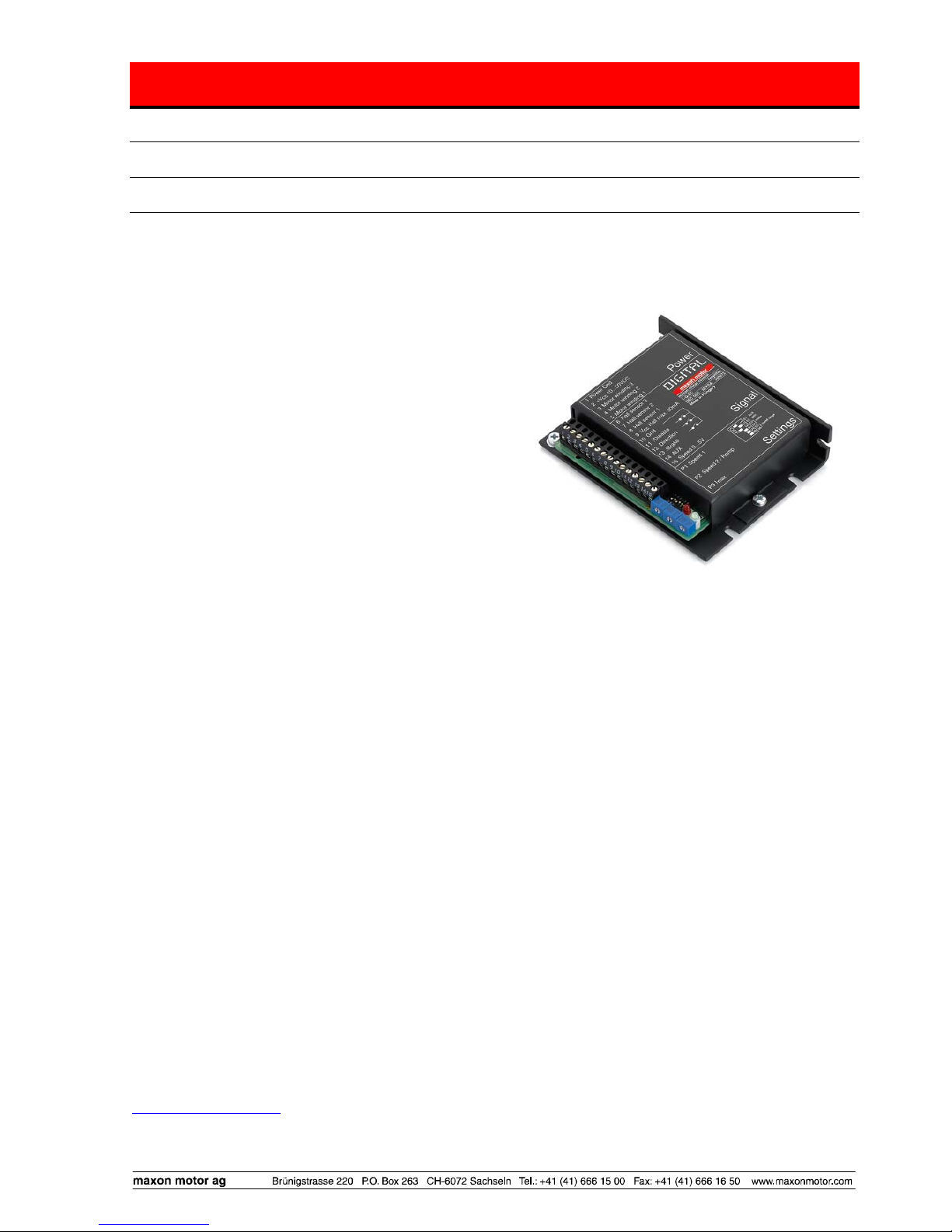
Operating Instructions 1-Q-EC Amplifier DEC 50/5
2 Performance Data
2.1 Electrical data
Supply voltage VCC (Ripple < 5 %)..............................................................................10 - 50 VDC
Max. output voltage........................................................................................................ 0.95 · VCC
Continuous output current Icont ..................................................................................................5 A
Max. output current Imax...........................................................................................................10 A
Switching frequency............................................................................................................39 kHz
Max. speed (motor with 1 pole pair)...........................................................................120 000 rpm
2.2 Inputs Speed .....................................................................................................analogue input (0 ... 5 V)
Resolution: 1024 steps
/Disable............................................................................TTL, CMOS (5V) or switch against Gnd
Direction.........................................................................TTL, CMOS (5V) ) or switch against Gnd
/Brake ............................................................................TTL, CMOS (5V) ) or switch against Gnd
Hall sensor...........................................................................................................................1, 2, 3
2.3 Inputs / outputs
AUX (configurable).............................................................................digital input / +5 VDC output
2.4 Voltage outputs
Hall sensors supply voltage VCC Hall .....................................................7 ... 12 VDC, max. 30 mA
2.5 Motor connections
Motor winding 1
Motor winding 2
Motor winding 3
2.6 Trim potentiometers
Speed 1, Speed 2 / Ramp, Imax, gain
2.7 LED indicator
Operating indicator: green LED
Error indicator: red LED
2.8 Ambient temperature / humidity range
Operation...................................................................................................................-10 ... +45°C
Storage ......................................................................................................................-40 ... +85°C
No condensation...........................................................................................................20 ... 80 %
2.9 Protective functions
Heat monitoring of power stage.....................................................................................T > 100°C
Blockage protection .................. Motor current limit, if motor shaft is blocked for longer than 1.5 s
2.10 Mechanical data
Weight...................................................................................................................... approx. 155 g
Dimensions (L x W x H) ..........................................................see dimension drawing, chapter 13
Mounting plate ......................................................................................................for 4 screws M3
Mounting hole separation............................................................................................ 87 x 39 mm
2.11 Terminals PCB clamps (plug-in terminal clamps)..............................................................................15 poles
Pitch.............................................................................................................................3.5 mm
suitable for wire cross section ..... 0.14...1mm2multiple-stranded or 0.14...1.3mm2single wire
AWG 16-26
October 2008 Edition / Doc.No. 544910-06 / subject to change maxon motor control 3