maxon motor ADS_E 50/5 User manual

maxon motor control ADS_E 50/5
Order number 166143
Operating Instructions June 1999 edition
The ADS_E 50/5 is a powerful servo-
amplifier for driving permanent magnet
DC motors up to 250 Watts.
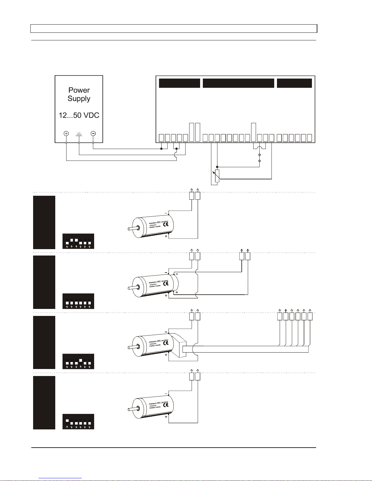
Four modes can be selected by
DIP switches on the board:
•Speed control using tacho signals
•Speed control using encoder signals
•I x R compensated speed control
•Torque or current control
The ADS_E 50/5 is protected against
excess current, excess temperature and
short circuit on the motor winding.
With the FET power transistors incorpo-
rated in the servoamplifier, an efficiency of
up to 95% is achieved.
A built in motor choke combined with the
high PWM frequency of 50 kHz allows the
connection of motors with a very low
inductivity.
In most cases an external choke can be
omitted.
Thanks to the wide input power supply range of 12 - 50 VDC, the ADS_E 50/5 is very versatile and can be used
with various power supplies.
The Europa card size allows the unit to be installed in a 19“-subrack or in a plug-in card system. Thanks to the
controller circuit design, the ADS_E 50/5 is easily and quickly installed.
Table of Contents
1 Safety Instructions.............................................................................................................................................2
2 Performance Data..............................................................................................................................................3
3 Minimum External Wiring for Different Modes of Operation ..............................................................................4
4 Operating Instructions........................................................................................................................................5
5 Functions ...........................................................................................................................................................7
6 Additional Possible Adjustments......................................................................................................................10
7 Error Handling..................................................................................................................................................11
8 Block Circuit Diagram......................................................................................................................................12
9 Pin Allocation Connector DIN 41612 Version H7/F24...................................................................................12
10 Dimension Drawing..........................................................................................................................................13
11 Accessories (not part of delivery) ...................................................................................................................13
The latest edition of this operating instructions may also be found in the internet under
http://www.maxonmotor.com («Downloads» in the category «Service & Support»).

maxon motor
4-Q-DC Servoamplifier ADS_E 50/5 Operating Instructions
2maxon motor control June 1999 edition / subject to change
1 Safety Instructions
Skilled Personnel
Installation and starting of the equipment shall only be performed by experienced,
skilled personnel.
Statutory Regulations
The user must ensure that the servoamplifier and the components belonging to it
are assembled and connected according to local statutory regulations.
Load Disconnected
For primary operation the motor should be free running, i.e. with the load
disconnected.
Additional Safety Equipment
An electronic apparatus is not fail-safe in principle. Machines and apparatus must
there-fore be fitted with independent monitoring and safety equipment. If the
equipment breaks down, if it is operated incorrectly, if the control unit breaks down
or if the cables break, etc., it must be ensured that the drive or the complete
apparatus is kept in a safe operating mode.
Repairs
Repairs may be made by authorised personnel only or by the manufacturer. It is
dangerous for the user to open the unit or make repairs to it.
Danger
Do ensure that during the installation of the ADS_E 50/5 no apparatus is connected
to the electrical supply. After switching on, do not touch any live parts.
Max. Supply Voltage
Make sure that the supply voltage is between 12 and 50 VDC. Voltages higher
than 50 VDC or of wrong polarity will destroy the unit.
Motor choke
The built in motor choke allows operation with almost all maxon DC motors with an
output power higher than 10 Watt. For a few exeptions (A-max ∅26, 11W as well
as RE ∅25 and RE ∅26 with terminal inductance lower than 0.35 mH) an extra
inductance (choke) of at least 200 µH is necessary.
Electrostatic Sensitive Device (ESD)

maxon motor
Operating Instructions 4-Q-DC Servoamplifier ADS_E 50/5
June 1999 edition / subject to change maxon motor control 3
2 Performance Data
2.1 Electrical data Supply voltage Vcc (Ripple < 5%)................................................................12 - 50 VDC
Max. output current Imax............................................................................................10 A
Continuous output current Icont ................................................................................... 5 A
Switching frequency............................................................................................. 50 kHz
Efficiency................................................................................................................. 95 %
Band width current controller .............................................................................. 2.5 kHz
Built-in motor choke .....................................................................................160 µH/5A
2.2 Inputs Set value................................................................................-10 ... +10 V (Ri=20kΩ)
Enable................................................................................+4 ... +50 VDC (Ri=15kΩ)
Input voltage DC tacho.....................................min. 2 VDC, max. 50 VDC (Ri=14kΩ)
Encoder signals...............................................Encoder A, A\, B, B\, max. 100 kHz, TTL
2.3 Outputs Current monitor „Monitor I“ , short-circuit protected.........-10 ...+10 VDC (RO=10kΩ)
Speed monitor „Monitor n“ , short-circuit protected..........-10 ...+10 VDC (RO=10kΩ)
Status reading „READY“
Open collector......................................................................max. 30 VDC (IL<20mA)
2.4 Voltage outputsAux. voltage, short-circuit protected.............................+12 VDC, -12 VDC, max. 12 mA
Encoder supply voltage..................................................................+5 VDC, max. 80 mA
2.5 Trim potentiometers
IxR
Offset
nmax
Imax
gain
2.6 LED indicator 2 colors LED......................................................................................... READY /ERROR
green = READY, red = ERROR
2.7 Ambient temperature- / Humidity range
Operating ................................................................................................... -10 ... +35 °C
Storage....................................................................................................... -40 ... +85 °C
noncondensating............................................................................................ 20 ... 80 %
2.8 Mechanical data
Weight...............................................................................................................ca. 315 g
Dimensions .................................................................................see dimension drawing
2.9 Terminal Connector DIN 41612 .............................................................................Version H7/F24

maxon motor
4-Q-DC Servoamplifier ADS_E 50/5 Operating Instructions
4maxon motor control June 1999 edition / subject to change
3 Minimum External Wiring for Different Modes of Operation
123456 ON
OFF
1 2 3456 ON
OFF
1 2 3456 ON
OFF
1 2 3456 ON
OFF
current mode
I x R compensation
EMF feedback
sensor selection
encoder frequency
current limit mode
current mode
I x R compensation
EMF feedback
sensor selection
encoder frequency
current limit mode
current mode
I x R compensation
EMF feedback
sensor selection
encoder frequency
current limit mode
current mode
I x R compensation
EMF feedback
sensor selection
encoder frequency
current limit mode
Enable
10 k
Ω
IxR
TachoEncoder
Current
z32
z32
d22
d22
z28
z24
/
d30
z20
/
d26
b16
z10
d10
z8
d16
d14
d8
d6
b12
/
b14
b2
b8
b6
z4
d4
z2
d2
z16
z14
Power Gnd
Power Gnd
+Vcc 12-50 VDC
+Vcc 12-50 VDC
Ground Safety Earth
- Motor
+Motor
Gnd
-12V
/
12mA OUT
+12V
/
12mA OUT
Ready
Monitor I
Monitor n
- Tacho Input
+Tacho Input
Gnd
Enable
-Setvalue
+Set value
Encoder B
Encoder B
/
EncoderA
EncoderA
/
Gnd
+5V
/
80mA
Power Signal Encoder
z24z24z24z24 z20z20z20z20
z14
z16
d2
z2
d4
z4
d8
d6

maxon motor
Operating Instructions 4-Q-DC Servoamplifier ADS_E 50/5
June 1999 edition / subject to change maxon motor control 5
4 Operating Instructions
4.1 Determine power supply requirements
You may make use of any available power supply, as long as it meets the
minimal requirements spelled out below.
During set up and adjustment phases, we recommend separating the motor
mechanically from the machine to prevent damage due to uncontrolled motion.
Power supply requirements
Output voltage Vcc min. 12 VDC; max. 50 VDC
Ripple < 5 %
Output current 5 A continuous (10 A peak)
The required voltage can be calculated as follows:
Known values:
•Operating torque MB[mNm]
•Operating speed nB[min-1]
•Nominal motor voltage UN[Volt]
•Motor no-load speed at UN,n
0[min-1]
•Speed/torque gradient of the motor ∆n/∆M [min-1 mNm-1]
Sought values:
•Supply voltage Vcc [Volt]
Solution:
Choose a power supply capable of supplying this calculated voltage under load.
The formula takes a 2 Volt max. voltage drop at the ADS_E 50/5 into account.
4.2 Function of the potentiometers
Potentiometer Function Turn to the
left right
P1 I x R I x R compensation weak
compensation strong
compensation
P2 Offset Adjustment n=0
at set value 0V motor turns
CCW motor turns
CW
P3 nmax max. speed
at 10V set value speed
slower speed
faster
P4 Imax current limit lower
min. 0.5 A higher
max. 10 A
P5 gain amplification lower higher
P6
P7
P8
•For additional possible adjustments refer to chapter 6.
•In use with the original frontplate, the potentiometers are covered !

maxon motor
4-Q-DC Servoamplifier ADS_E 50/5 Operating Instructions
6maxon motor control June 1999 edition / subject to change
4.3 Adjustment of the Potentiometers
4.3.1 Pre-adjustment
With the pre-adjustment, the potentiometers are set in a preferred position.
ADS_E units in original packing are already pre-adjusted.
4.3.2 Adjustment
Encoder mode
DC-Tacho mode 1. Adjust set value to maximum (e.g. 10V) and turn potentiometer P3 nmax
so far that the required speed is achieved.
I x R compensation 2. Set potentiometer P4 Imax to the limiting value desired.
Important
: The limiting value lmax should be below the max. continuous
current as shown on the motor data sheet.
3. Increase potentiometer P5 gain slowly until the amplification is set large
enough.
Caution:
If the motor vibrates or becomes loud, the amplification is
adjusted too high and the potentiometer must be readjusted until the
instability of the closed loop of the drive under all loads disappears.
4. Adjust set value to zero, e.g. by short circuiting the set value input (link
pins [b6] and [b8]). Then set the motor speed to zero with the potentio-
meter P2 Offset.
In addition, only in the case of lxR compensation:
5. Slowly increase potentiometer P1 IxR until the compensation is set large
enough so that in the case of high motor load the motor speed remains
the same or decreases only slightly.
Current controller mode 1. Set potentiometer P4 lmax at the limiting value desired.
Important
: The limiting value lmax should be below the max. continuous
current as shown in the motor data sheet.
Pre-adjustment
P1 I X R 0 %
P2 Offset 50 %
P3 nmax 50 %
P4 Imax 50 %
P5 gain 10 %
P6
n
gain
25 %
P7
I
gain
50 %
P8
I
cont
50 %
Additional possible
adjustments:
refer to section 6.1/6.2
Adjustment:
refer to section 4.3.2

maxon motor
Operating Instructions 4-Q-DC Servoamplifier ADS_E 50/5
June 1999 edition / subject to change maxon motor control 7
5 Functions
5.1 Inputs
5.1.1 Set value
The set value input is wired as a differential amplifier.
Input voltage range -10...+10 V
Input resistance 20 kΩ
Positive set value ( + set value [b6]) >( - set value [b8])
Negative set value ( + set value [b6]) <( - set value [b8])
5.1.2 Enable
If a voltage is given at “Enable”, the servoamplifier switches the motor voltage to
the winding connections. If the “Enable” input is not switched on or is connected
to the Gnd, the power stage will be highly resistant and will be disabled.
The “Enable” input is short-circuit protected.
Enable Minimum input voltage + 4,0 VDC
Maximum input voltage + 50,0 VDC
Input resistance 15 kΩ
Switching time typ 500 µsec (by 5 V)
Disable Minimum input voltage 0VDC
Maximum input voltage + 2,5 VDC
Input resistance 15 kΩ
Switching time typ 100 µsec (by 0 V)
5.1.3 DC Tacho
Minimum input voltage 2,0 V
Maximum input voltage 50,0 V
Input resistance 14 kΩ
The nmax potentiometer allows you to adjust the motor speed for a given set
value input.
The lowest adjustable motor speed range is ±3850rpm with a ±10V set value
and a tacho with 0.52V/1000rpm.
(3850rpm x 0.52V/1000rpm = 2V ; see table above)
Lower speed ranges can be achieved either by reducing the set value input
range (i.e. ±5V for ±1925rpm) or using a tacho type with higher output voltage,
such as 5V/1000rpm.

maxon motor
4-Q-DC Servoamplifier ADS_E 50/5 Operating Instructions
8maxon motor control June 1999 edition / subject to change
5.1.4 Encoder
Encoder supply voltage + 5 VDC max. 80 mA
Maximum encoder frequency DIP - Switch 5 ON: 10 kHz
DIP - Switch 5 OFF: 100 kHz
Voltage value TTL
low max. 0,8 V
high min. 2,0 V
It is strongly recommended that the encoder be used with a built-in line driver.
If the encoder is used without a line driver (without EncoderA\ and EncoderB\),
speed breakdowns and max. speed limits must be expected because of the
slower switching slope.
The servoamplifier does not need any home impulse I and I\.

maxon motor
Operating Instructions 4-Q-DC Servoamplifier ADS_E 50/5
June 1999 edition / subject to change maxon motor control 9
5.2 Outputs
5.2.1 Current monitor „Monitor I“
The servoamplifier makes a current actual value available for monitoring
purposes. The signal is proportional to the motor current.
The „Monitor I“ output is short-circuit protected.
Output voltage range -10... +10 VDC
Output resistance 10 kΩ
Gradient approx. 0,8 V / A
5.2.2 Speed monitor „Monitor n“
The speed monitor is primarily intended for the qualitative estimation of the
dynamics. The absolute speed is determined by the properties of the speed
sensors and by the setting of the nmax potentiometer. The output voltage of the
speed monitor is proportional to the number of revolutions. The output voltage
of the speed monitor is 10V when the maximum number of revolutions set by
the nmax potentiometer has been reached.
The “Monitor n” output is short-circuit protected.
Output voltage range -10... +10 VDC
Output resistance 10 kΩ
5.2.3 Status reading „Ready“
The “Ready“ signal can be used to report the state of operational readiness or a
fault condition on a master control unit. The „Open Collector“ output is, in
normal cases, i.e. no faults, switched to Gnd. In the case of a fault due to
excess temperature or excess current, the output transistor is not conducting
(high resistance).
An external additional voltage is required:
Input voltage range max. 30 VDC
Load current <20 mA
The fault condition is stored. In order to reset the fault condition, the servoampli-
fier must be re-released (Enable). If the cause of the fault situation cannot be
removed, the output transistor will immediately change to the not conducting
state again.

maxon motor
4-Q-DC Servoamplifier ADS_E 50/5 Operating Instructions
10 maxon motor control June 1999 edition / subject to change
6 Additional Possible Adjustments
Potentiometer Function Position
left right
P6 ngain speed gain low high
P7 Igain current gain low high
P8 Icont continuous current limit lower higher
6.1 Adjustments potentiometer P6 ngain and potentiometer P7 Igain
In most applications, regulation setting is completely satisfactory using potentio-
meters P1 to P5. In special cases the transient response can be optimized by
setting the P6 “speed regulation gain” potentiometer. The P7 “current regulator
gain” potentiometer can, in addition, be adapted to the dynamics of the current
regulator.
It is recommend that the success of changes to the settings of P6 ngain and P7
Igain be checked by measuring the transient response with an oscilloscope at the
“Monitor n” and “Monitor I” outputs.
Pre-adjustment P6 ngain = 25 % and P7 Igain =50%.
6.2 Adjustments potentiometer P8 Icont and current limit mode DIP-Switch 6
It is standard that a maximum current limiter is activated (DIP switch 6 OFF) as
the only current limiter. In this way the motor current is limited to the value set
on potentiometer P4 Imax (0.5 ... 10A).
If DIP switch 6 is turned to ON, a cyclical current limiter is also activated. This
current limiter method makes a certain level of motor protection against thermal
overload possible.
For 0.1 seconds the motor current is limited to the value set on potentiometer
P4 Imax (0.5 - 10A) and then for 0.9 seconds current is limited to the value set on
potentiometer P8 Icont (0.5 - 10A). After one second a current of lmax is allowed.
Pre-adjustment P8 Icont = 50%.
DIP-Switch 6 ON ↑DIP-Switch 6 OFF ↓
cyclical current limiter active maximum current limit active
P4 Imax
t
Imax
P4 Imax
t
1sec0.1 sec
Imax
Icont P8 Icont

maxon motor
Operating Instructions 4-Q-DC Servoamplifier ADS_E 50/5
June 1999 edition / subject to change maxon motor control 11
6.3 Maximal encoder frequency DIP-Switch 5
DIP switch 5 permits selection of the maximum encoder input frequency.
A max. encoder frequency of 100 kHz is standard.
DIP-Switch 5 ON ↑DIP-Switch 5 OFF ↓
Max. Input frequency is 10 kHz Max. Input frequency is 100 kHz
Encoder pulse
per turn maximum
motor speed Encoder pulse
per turn maximum
motor speed
100 6’000 rpm 100 60’000 rpm
500 1’200 rpm 500 12’000 rpm
1000 600 rpm 1000 6’000 rpm
7 Error Handling
Defect Possible source of defect Measures
Shaft does not rotate Supply voltage < 12 VDC check power plug pin [d22]
Enable not activated check signal plug pin [b2]
Set value is 0V check signal plug pin [b6] and pin [b8]
Current limit too low check adjustment pot. P4 Imax
Wrong operational mode check DIP switch settings
Bad contacts check wiring
Wrong wiring check wiring
Speed is not controlled Encoder mode: encoder signals check encoder signal
DC- Tacho mode: tacho signals check pin [d6] and [d8] (polarity)
I x R mode: compensation wrong check adjustment pot. P1 I x R

maxon motor
4-Q-DC Servoamplifier ADS_E 50/5 Operating Instructions
12 maxon motor control June 1999 edition / subject to change
8 Block Circuit Diagram
MOSFET
Full-Bridge
J301
J302
J303
J305
J304
+Motor
-Motor
Power Gnd
+Vcc 12-50VDC
PWM,
Control &
Protection
Logic
Current
Detector Voltage
Detector
Monitor I
Current
limit
+12V
P8 I cont
P4 Imax
DIP6
P7 I gain
P6 n gain
P5 gain
DIP2
DIP3
+12V -12V
P2 Offset
P3 n max
-Tacho Input
Monitor n
DIP1
-Set value
+Set value
F/V Converter
+5V/80mA
Gnd
Encoder A
Encoder A\
Encoder B
Encoder B\
DIP5
DIP4
+5V
+12V
-12V
Supply
+12V -12V
+12V OUT -12V OUT Enable Ready
1K 1K
10K
10K
P1 IxR
9 Pin Allocation Connector DIN 41612 Version H7/F24
Encoder A\ Enable Encoder A
d
2bz
Encoder B\ n.c. Encoder B
4
6
+ Tacho Input + Set value n.c.
dbz
8
10
12
14
16
- Tacho Input - Set value Ready
+12V/12mA OUT n.c. -12V/12mA OUT
n.c. Gnd n.c.
Monitor n Gnd + 5V/80mA
Monitor I Gnd Gnd
20
+Motor
22
+Vcc 12-50VDC
24
- Motor
26
+Motor
28
Ground Safety Earth
30
- Motor
32
Power Gnd

maxon motor
Operating Instructions 4-Q-DC Servoamplifier ADS_E 50/5
June 1999 edition / subject to change maxon motor control 13
10 Dimension Drawing
160 max. 0.5 TE
1.6
21.6
3.57
5.55 88.9
100
(2.54)
123456
2.8
11 Accessories (not part of delivery)
11.1 Front panel: Order number 167850
128.4
25.06 2.5
maxon motor
Dimensions in [mm]
Dimensions in [mm]
clear anodised
5TE,3HE

maxon motor
4-Q-DC Servoamplifier ADS_E 50/5 Operating Instructions
14 maxon motor control June 1999 edition / subject to change
11.2 Backplane with screw terminals: Order number 166873
23
130
.................[z14]
...........................[z16]
.................[d 2]
..................[z 2]
.................[d 4]
..................[z 4]
..................[b 6]
..................[b 8]
........................[b 2]
..................[b14 / b12]
..............[d 6]
..............[d 8]
...................[d14]
....................[d16]
.........................[z 8]
.......[d10]
.......[z10]
...........................[b16]
..............[d26 / z20]
..............[d30 / z24]
..[z28]
.......[d22]
.......[d22]
................[z32]
+5V/80mA
Gnd
Encoder A\
Encoder A
Encoder B\
Encoder B
+Set value
-Setvalue
Enable
Gnd
+Tacho Input
- Tacho Input
Monitor n
Monitor I
Ready
+12V/12mA OUT
-12V/12mAOUT
Gnd
+Motor
- Motor
Ground Safety Earth
+Vcc 12-50 VDC
+Vcc 12-50 VDC
Power Gnd
Power Gnd
1
2
3
4
5
6
1
2
3
4
5
6
7
8
9
10
11
12
1
2
3
4
5
6
7
11.6
1.6
EncoderSignalPower
No. of poles Pitch suitable for wire cross section
Encoder 6 3.81 [mm] 0.14 - 1.5 [mm2] (single wire)
0.10 - 1.0 [mm2] (multiple-stranded wire)
Signal 12 3.81 [mm] 0.14 - 1.5 [mm2] (single wire)
0.10 - 1.0 [mm2] (multiple-stranded wire)
Power 7 5.08 [mm] 0.14 - 1.5 [mm2] (single wire)
0.14 - 1.5 [mm2] (multiple-stranded wire)
Dimensions in [mm]
This manual suits for next models
1
Table of contents
Other maxon motor Amplifier manuals