maxxkool MK13000 User manual

RECORD THIS UNIT INFORMATION FOR FUTURE REFERENCE:
Model Number:
Serial Number:
Date Purchased:
This manual must be read and understood before installation, adjustment, service, or maintenance
is performed. This unit must be installed by a qualified service technician. Modification of this
product can be extremely hazardous and could result in personal injury or property damage.
AIR CONDITIONER & HEAT PUMP
DIGITAL CONTROL FOR DUCTED SYSTEM
INSTALLATION AND OPERATING INSTRUCTIONS
FOR MK13000
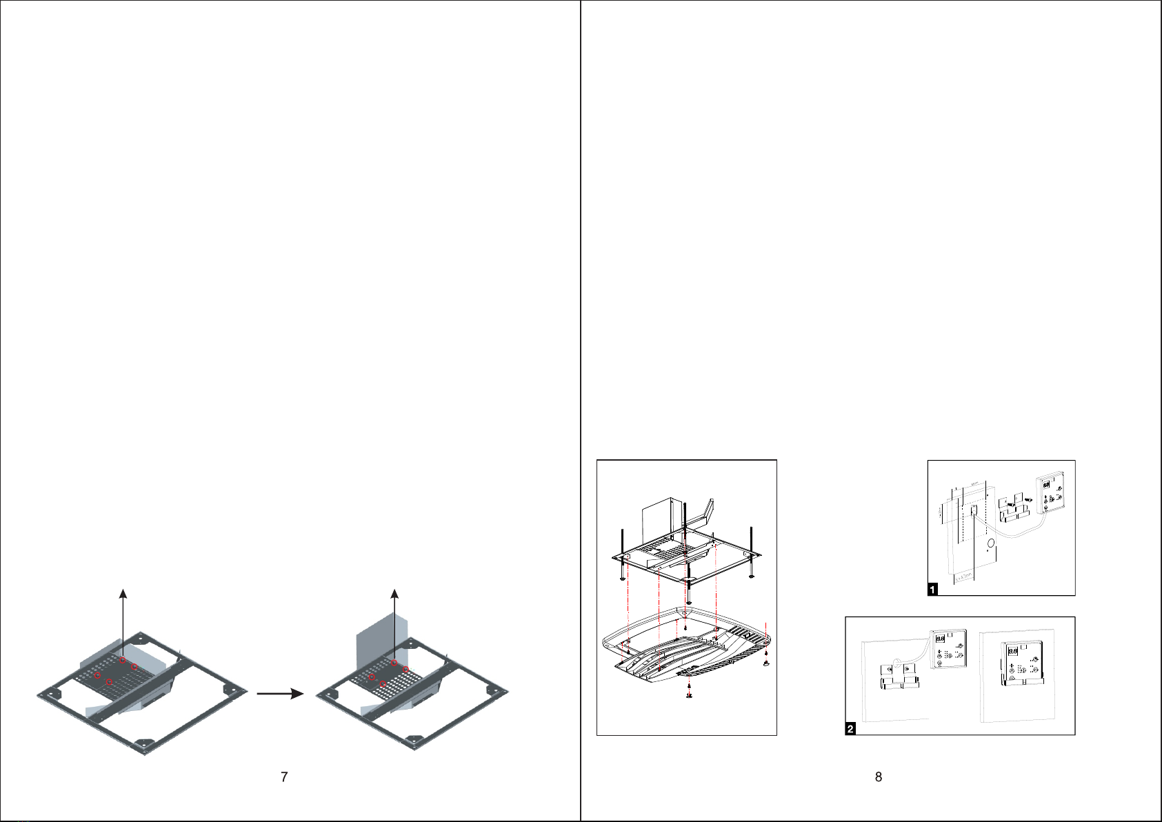
CONNECTING 220VAC WIRING
1. WARNING - SHOCK HAZARD: To prevent the possibility of severe personal injury
or equipment damage due to electrical shock, always be sure the electrical power
is disconnected or off before beginning installation.
2. Route the 220VAC supply wiring previously routed into the frame of the roof
opening, through the strain relief of the electrical box and into the high voltage
wiring area.
TO PREVENT THE POSSIBILITY OF SHOCK INJURY FROM APPLIANCE
OPERATION: THE WHITE WIRE MUST BE CONNECTED TO NEUTRAL IN THE
SERVICE BOX ENTRANCE AND THE GREEN GROUND WIRE MUST BE
CONNECTED TO A GROUNDING SCREW.
ATTACH CEILING GRILL
1. Position the grill next to the interior frame and attach it with the provided screws.
2. Install the filter on the air intake grill section.
3. Snap the intake grill section onto the main grille.
4. Install the screw covers.
MAINTENANCE
1. AIR FILTER:
Remove the return air filter (after every 30 days of use) located above the removable
air intake grill. Wash the filter with soap and warm water, let dry and then reinstall.
Note: Never run the air conditioner / heat pump without putting the air filter back in
place. This may plug the indoor coil with dirt and may substantially affect the
performance of the unit.
2. Air Return Grill:
Clean panel and control panel with a soft cloth dampened with a mild detergent. Never
use furniture polish or harsh chemicals.
3. FAN MOTOR:
Factory lubricated and requires no service.
4. FROST FORMATION ON COOLING COIL:
Under certain conditions, frost may form on the indoor coil. If this should occur, inspect
the filter and clean if dirty. Make sure air louvers are not obstructed. Air conditioners /
heat pumps have a greater tendency to frost when the outside temperature is relatively
low. This may be prevented by adjusting the thermostat control to a warmer setting.
SERVICE
If the unit does not operate:
1. If RV is connected to a generator, check to be sure generator is running and producing
the proper power.
2. If RV is connected to shore power, check to be sure supply breaker is sized properly to
run air conditioner / heat pump load and it is plugged into power supply.
3. Check your fuse or circuit breaker to see if it is off.
4. After the above checks, call your local service center for further help. This unit must be
serviced by qualified service personnel only.

INSTALLATION & OPERATING INSTRUCTIONS
These instructions must stay with the unit
Safety Instructions
This manual has safety information and instructions to help users eliminate or reduce the risk of
accidents and injuries.
Read and follow all safety information, installation guides, recommended precautions, and safe
operating instructions.
GENERAL INFORMATION
A. This air conditioner / heat pump is designed for:
1. Installation on a recreational vehicle.
2. Mounting on the roof of a recreational vehicle.
3. Roof construction with rafters/joists on 16 inch centers.
4. 1.18" inch thick roofs.
B. The efficiency of the air conditioner / heat pump will be affected by the
conditions inside and outside of the RV. Reducing the heat gain of the RV will
allow the air conditioner / heat pump to function with greater efficiency. Here
are some suggestions to reduce heat gain in your RV.
1. Select a shaded area to park your RV
2. Close windows and utilize the blinds and / or curtains.
3. Keep doors shut.
4. Avoid using appliances that produce heat.
Beginning the cooling / heating process early in the day will greatly improve the heat pump’s
ability to maintain the desired temperature.
In high temperature and high humidity environments, the air conditioner / heat pump should be
set in Cool mode with the Fan Speed in the high position, This will allow for optimal cooling
efficiency.
C. Condensation
The manufacturer of this air conditioner / heat pump will not be responsible for
damage caused by condensed moisture on ceilings or other surfaces, Air contains
moisture and this moisture tends to condense on cold surfaces, When air enters
the RV, condensed moisture may appear on the ceiling, windows, metal parts, etc.
The air conditioner / heat pump removes this moisture from the air during cooling
operation, Keeping doors and windows closed when this air conditioner /heat
pump is operating will minimize condensation.
Timer off mode
Timer on mode

Notes:
1. Consult the National Electric Code for proper sizing for wire lengths over 24 ft.
2. When sizing the generator, the total power usage of your recreational vehicle
must be considered. Keep in mind generators lose power at high altitudes and
from lack of maintenance.
3. CIRCUIT PROTECTION: Time Delay Fuse or HACR Circuit Breakers Required.
INSTALLATION INSTRUCTIONS
1. PRECAUTIONS
2. CHOOSING A LOCATION FOR THE AIR CONDITIONER / HEAT PUMP
A. Read installation and operating instructions carefully before attempting to start
your air conditioner / heat pump installation.
B. The manufacturer will not be liable for any damages or injury incurred due to
failure to follow these instructions.
C. Installation must comply with the National Electrical Code and any State or
Local Codes or regulations.
D. DO NOT add any devices or accessories to this air conditioner / heat pump
except those specifically authorized by manufacturer.
E. This equipment must be serviced by qualified personnel and some states
require licensed personnel.
This product is designed for use as a RV roof top air conditioner / heat pump. The
use of this product in other applications will void the manufactures warranty.
A. NORMAL LOCATIONS:
The unit is designed to fit over an existing roof vent opening. When the vent is
removed, it normally creates a 14-1/4" x14-1/4"±1/8" opening.
B. OTHER LOCATIONS:
When a roof vent is not available or another location is desired, the following
is recommended:
220VAC
/60Hz/
1PH
Model
MK13000
Cooling
capacity
(BTU/h)
13000
Electrical
rating
Compressor
rated load
(Amps)
6.6
Compressor
locked
rotor
current
(Amps)
26
Airflow
(High
speed)
3
(m /h)
550
Refrigerant
(R410a)
(oz.)
20.1
Min. wire
size
12AWG
copper
up to
24'
AC circuit
protection
(User
supplied)
20Amp
Unit
dimensions
(mm)
788x632
x256
Packing
dimensions
(mm)
855x655
x315
Weight
(net/grass)
(kg.)
32/36
Heating
capacity/
Electrical
heater
(BTU/h)
13000
Fanmotor
rated
load
(Amps)
1.1
Fanmotor
locked
rotor
(Amps)
2.5
Heat pump mode
Night mode

1. For one unit installation: The air conditioner / heat pump should be mounted slightly
forward of center (front to back) and centered from side to side. See FIG.1.
2. For two unit installation: Install one air conditioner / heat pump 1/3 distance and the
other air conditioner / heat pump 2/3's from front of RV and centered from side to side.
See FIG.2.
It is preferred that this air conditioner / heat pump be installed in a relatively flat and
level roof section measured with the RV parked on a level surface; however, up to 15
degree slant to either side, or front-to-back is acceptable.
FIGURE 1
FIGURE 2
Dehumidification mode
Ventilation mode

C. POST LOCATION SELECTION:
1. Check for obstructions in the area where air conditioner / heat pump will be
installed. A minimum clearance of 18" is required for the rear section of the air
conditioner / heat pump to any other roof mounted object.
2. The roof must be capable of supporting 100 Ibs while the RV is in motion. Normally,
a 200 Ib. static load design will meet this requirement.
3. ROOF PREPARATION
A. EXISTING ROOF VENT REMOVAL:
1.Unscrew and remove the roof vent.
2. Remove all caulking compound around opening.
3. Seal all screw holes and seams where the roof gasket will be located. Use a good
grade of all weather sealant.
B. NEW OPENING:
1.A 14-1/4" x 14-1/4"+1/8" opening must be cut through the roof and ceiling of the RV.
It is recommended this opening be located between roof framework.
2. Mark a 14-1/4" x 14-1/4" square on the roof and carefully cut the opening.
3. Using the roof opening as a guide, cut the matching hole in the ceiling. See FIG.3.
There may be electrical wiring between the roof and the
ceiling. Disconnect 220 volt AC power cord .
Failure to follow this instruction may create a shock
hazard causing death or severe personal injury.
WARNING
!
FIG.3
Automatic mode
Cold mode

C. OPENING PREPARATION:
1. If the opening exceeds 14-3/8" x 14-3/8", it will be necessary to install spacers.
2. If the opening is less than 14-1/8" x 14-1/8", it must be enlarged.
3. Route a 12/3 Rmoex type supply line from the circuit breaker box to the Front of
the roof opening.
a. The power supply must be on a separate 20 amp Time Delay Fuse or HACR
Circuit Breaker.
b. Wiring must comply with all National, State and Local wiring codes.
c. Make sure at least 15" of wire extend into the roof opening to ensure easy
connections.
4. The opening must be framed to provide adequate support and prevent air from
being drawn from the roof cavity. Lumber 3/4" thick or more and long enough to
bridge the opening must be used. Remember to provide an entrance hole in the
front of the opening for 220v, and thermostat wires. See FIG.4.
5. The 14-1/4" x14-1/4"(+1/8) roof opening is part of the return air duct and must be
finished in accordance with National Code, regulations related to RV Industrial.
CAUTION
It is the responsibility of the installer of this system to ensure structural
integrity of the RV roof. Never create a low spot on the roof where water
will collect. Water standing around the air conditioner/heat pump may
leak into the interior causing damage to the product and RV
FIG.4
Description of the controls
Selecting functional status
Press the “MODE” button to move between the possible states (automatic, cold,
dehumidification,ventilation, heat pump) and wait two seconds on the selected state
for this to be confirmed by the system with an audible warning (the buzzer is inside the
machine). Always point the remote control towards the wall pad to send all the signals.
At the time of switching on, the system waits for a few minutes before operating
the compressor.

AIR RETURN GRILL INSTALLATION (ACRG15)
The Air Return Grill is designed for application in systems that utilize field fabricated
(OEM supplied)air ducting. The ducting must be routed through the ceiling cavity
(between the interior ceiling and roof). Ducting specifications are given in the section
labeled Supply Ducting and Registers.
INSTALLATION REQUIREMENTS
(ROOF THICKNESS MUST BE AT LEAST 1.18")
1. The ACRG15 must be installed under the roof opening. The ACRG15 bolts to the
underside of the roof unit. Compression of the framed ceiling cavity between the
unit and the ACRG15 is what holds both components in place.
2. Ceiling cavity depth (the measurement from the ceiling to the roof):
3. The 220 VAC service for the air conditioner / heat pump must be routed into the
ACRG15 (refer to Fig.5 below).
roof
1.18" .
FIGURE 5 WIRING DIAGRAM FOR HEAT PUMP
4WAY VALVE
4.The ACRG15 has a 6pin, two 3 pin & two 2 pin connectors extending from the front of
the relay kit. These connectors mate with the air conditioner / heat pump. When
making this connection, verify that the plugs are properly aligned and have snapped
together securely.
5.Provided with the ACRG15,is a divider plate which is used to separate the warm return
air from the cold supply air. If the roof thickness is greater than 1.18", you MUST use the
additional divider provided.
Description of the wall pad
1. Signal receiver
2. Press the ON/OFF button to switch ON or OFF the air conditioner, it will run
in memory mode.
3. Press the MODE button to select cooling or heating mode.
4. Press the FAN button to select fan speed.
5. Press the UP or DOWN button to select the desired temperature.
2
3
4
5
wall pad
1
Installing and changing the remote control batteries
Take off the battery cover.
Insert the two batteries supplied(size AAA), paying
attention to their polarity.
Fit the battery cover back on.
Check the remote control works properly by pressing
the on button: if, on pressing the button, no icon
appears on the display then you need to reinstall
the batteries checking their polarity. The machine
is connected tothe power supply and ready for use.
附件袋 :there is a pocket for wall pad, remote control with battery and support, and
extension cable. To fix wall pad on the wall, you need to make a diameter 20mm
hole for cable to pass through.(refer to drawing2). Using 2 wooden screws to fix
support to the wall, connect extension cable to wall pad then put wall pad into it’s
support.

3. Position the mount frame into the ceiling opening. See Figure 7.
4. Using the four bolts provided, hold up the mount template to the ceiling. The four
mounting bolts are to be inserted up through the bottom of the mount template and
into the bottom of the air conditioner / heat pump. Tighten all 4 boles equally to
compress gasket 33-35 inch pounds. When moving the air conditioner / heat pump
be sure not to damage the gasket by sliding it across the roof. If the gasket is
damaged and needs replaced, please contact MAXXKOOL and purchase an authorized
gasket for replacement. Using other gasket material is not recommended and could
result in warranty denial.
5. Install divider with foam seal against base pan of upper unit. On thinner roofs, the
divider may be too high, so break away additional portion. Remove paper cover on
fixed divider, insert loose divider against base pan and stick to fixed divider.
6. Cut the insulation to the height of the divider, center insulation on divider before
removing paper backing and apply to divider. Excess insulation will help ensure the
seal at the end of the divider/frame.
7. Connect 220VAC , Heat Pump specific
(Indoor Coil Thermistor, Indoor Ambient Thermistor), and thermostat cable
according to the wiring diagram. Install the cover over the electrical box using the
small screw provided .
8. Seal all seams between output airside and return airside with insulation and foil tape.
SUPPLY DUCTING AND REGISTERS
A. Ducting
1. The field fabricated supply ducting must attach to both sides of the ACRG15. A
minimum of two ducts are required, with one duct attached to each side of the plenum.
2. Each duct must have a minimum height of 1.18".
Total free area inside each duct must be no less than 10 square inches.
NOTE: To decrease restriction and increase airflow, the ducting should make as few
bends and turns as possible. When corners or turns are required, we recommend
that you add radii to the corners to keep airflow at a airflow and system
performance.
3. All field fabricated air supply ducting must be insulated to avoid condensation and
prevent cooling / heating loss.
B. Registers
Air registers should have a minimum discharge area of 48 square inches per system,
24 square inches per duct run.
Warnings about wiring:
1. It requires the power supply to be copper conductors with minimum
#12AWG.
2. To prevent voltage drops greater than 10% during starting loads, adhere to the
following guideline: For lengths greater than 50 feet, use #10 AWG.
or
TEMPLATE MOUNTING
Frame Mounting
1. Place the air conditioner / heat pump over the roof opening.
2. Remove the control box from the frame and reinstall it in vertical direction with the
four screws provided.
MAIN RELAY KIT WIRING
FIG.7
Unscrew Tighten screws
FIG.6
Fitting the infrared wall pad
Table of contents
Popular Heat Pump manuals by other brands

Johnson Controls
Johnson Controls JRC Series Installation operation & maintenance

Daikin
Daikin LXE10E-A32A Service manual and parts list

Marvair
Marvair GeoScholar Series manual

REMKO
REMKO RVT 264 ARCTIC Assembly and operating instructions

Heat Controller
Heat Controller AS-W303DPZ0 Service manual

Mitsubishi Heavy Industries
Mitsubishi Heavy Industries ESA30EH2-25 Technical manual

Polytropic
Polytropic PAC 16 Instruction handbook

AAON
AAON ProFit WH Series Installation operation & maintenance

HIdRos
HIdRos WHK Series Technical manual

All Swim
All Swim POOLSTYLE GHD-150-0318 Installation and user manual

ACS
ACS Eubank EAA1020H Installation & operation manual

York
York E9FD018 Series Installation instruction