MaxxOne Falcon User manual

www.maxxone.com
H.265 NETWORK VIDEO RECORDER
USER MANUAL

USER MANUAL
2

USER MANUAL
1
Contents
SAFETY INSTRUCTION............................................................................................... 3
CHAPTER 1 OVERVIEW OF NVR ................................................................................. 1
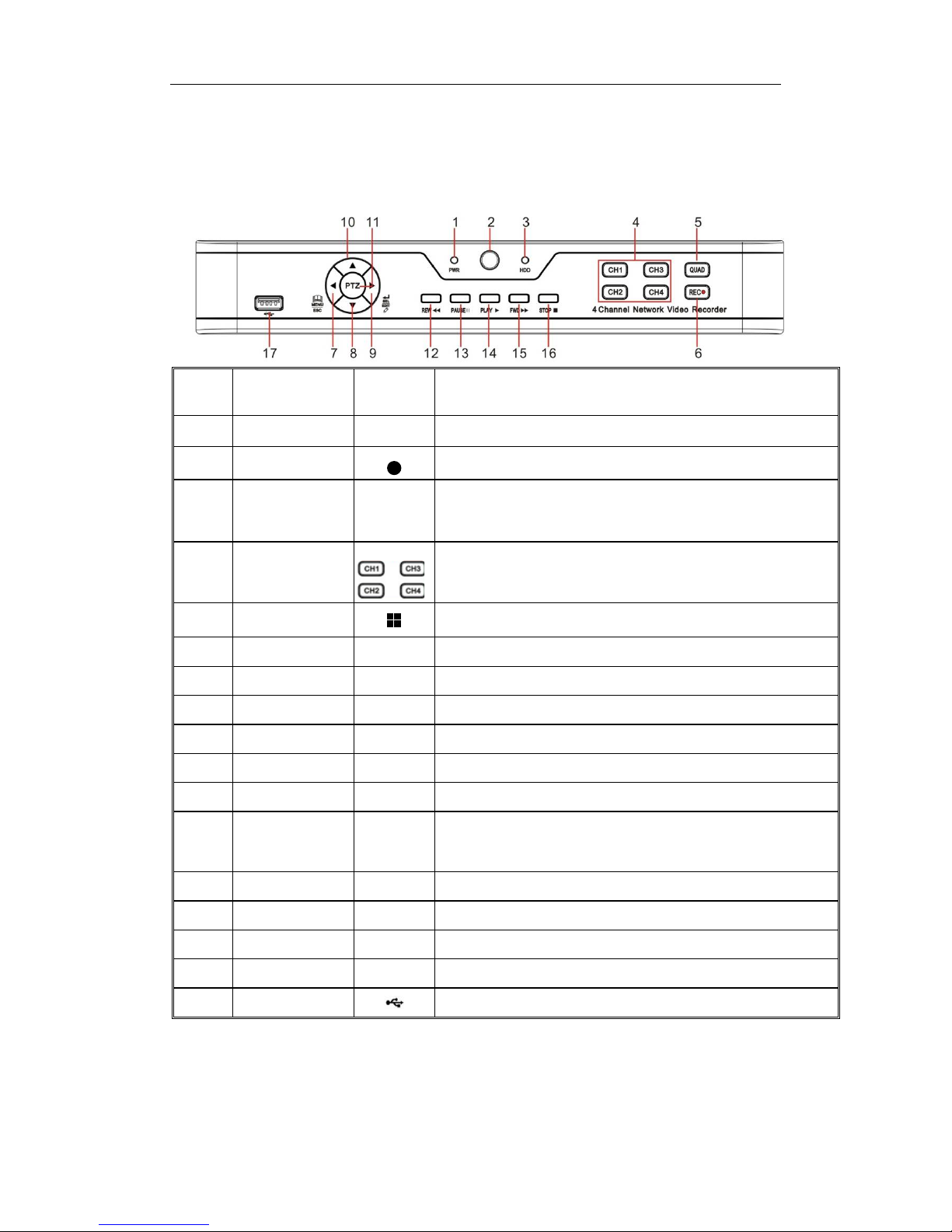
1.1 FRONT PANEL ...............................................................................................................1
1.2 REAR PANEL .................................................................................................................2
1.3 REMOTE CONTROLLER (FOR REFERENCE ONLY) ....................................................................3
CHAPTER 2 NVR CONNECTION .................................................................................. 3
2.1 HDD INSTALLATION .......................................................................................................3
2.2 WEB CAMERA AND MONITOR CONNECTION .......................................................................3
2.3 POWER SUPPLY CONNECTION ..........................................................................................3
CHAPTER 3 NVR BOOT UP......................................................................................... 4
3.1 SYSTEM INITIALIZATION...................................................................................................4
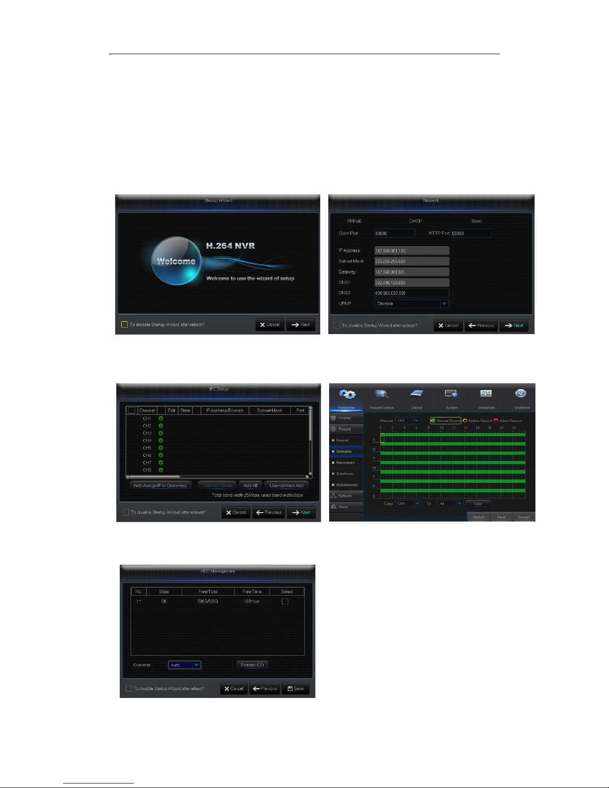
3.2 STARTUP WIZARD ..........................................................................................................5
3.3 MAIN INTERFACE ...........................................................................................................6
CHAPTER 4 NVR MENU ............................................................................................. 6
4.1 MAIN MENU GUIDE ......................................................................................................7
4.2 MAIN MENU ................................................................................................................8
4.2.1 Parameter ..........................................................................................................8
4.2.2 Record Search ..................................................................................................16
4.2.3 Device ..............................................................................................................20
4.2.4 System .............................................................................................................21
4.2.4 Log ...................................................................................................................23
4.2.5 Advanced .........................................................................................................24
4.2.6 Shutdown ........................................................................................................25
4.3 MENU LOCK ...............................................................................................................25
4.4 SPLIT MODE ...............................................................................................................26
4.5 RECORD SEARCH..........................................................................................................26
4.6 MUTE .......................................................................................................................26
4.7 START SEQUENCE.........................................................................................................26
CHAPTER 5 WEB APPLICATION MANAGER............................................................... 27
5.1 ACTIVEXCONTROL DOWNLOAD AND INSTALLATION .............................................................27
5.2 WEB APPLICATION MANAGER LOGIN ..............................................................................28
5.3 LIVE INTERFACE ...........................................................................................................28
5.3.1 Menu Bar.........................................................................................................29
5.3.2 Playback...........................................................................................................30
5.3.3 Parameter Setting............................................................................................33
5.3.4 Local Setting ....................................................................................................41
5.3.5 Logout..............................................................................................................41
CHAPTER 6 APPENDIX............................................................................................. 42

USER MANUAL
2
6.1 TROUBLESHOOTING......................................................................................................42
6.2 USAGE MAINTENANCE .................................................................................................43
CHAPTER 7 WARRANTY .......................................................................................... 44
7.1 LIMITED WARRANTY ....................................................................................................44
7.2 WARRANTY PERIOD .....................................................................................................44
7.3 WARRANTY EXCLUSIONS ...............................................................................................44
8.4 WARRANTY CLAIMS AND VALIDATION..............................................................................45
8.5 LIMITATION OF LIABILITY ...............................................................................................46
8.6 MISCELLANEOUS PROVISIONS ........................................................................................46
8.7 STANDARD WARRANTY CONDITIONS ...............................................................................46
8.8 REPAIR/REPLACEMENT PROCEDURE ................................................................................46

USER MANUAL
3
SAFETY INSTRUCTION
Please carefully read the following safety instruction so as to avoid personal injuries and prevent
the equipment and other connection devices from being damaged.
1. Use the power supply included or specified by the manufacturer only
Never operate the equipment using an unspecified or incompatible power supply.
2. Never push objects of any kind through openings of NVR
Never push objects of any kind through openings of NVR so as to avoid electric shock, fire or
other accidents.
3. Do not expose the equipment to dust
Clean around the device regularly to prevent overheating and damage.
4. Do not place the equipment under rain or humid environment
Do not place the equipment in humid environments like basements. If the equipment
accidentally comes in contact with water, please unplug the power cable immediately and
contact your local dealer.
5. Keep the surface of the equipment clean and dry
Use soft damp cloth to clean the outer case of NVR (do not use liquid aerosol cleaners).
6. Do not operate if any problems are found
If there are any strange smells or sounds coming from the NVR, unplug the power cable and
contact an authorized dealer or service center.
7. Do not try to remove the upper cover during operation
Warning: Do not remove the top cover of NVR so as to avoid electric shock.
8. Handle with care
Physical damage to this unit can cause it to fail to operate and you will need to contact an
authorized dealer for repair or replacement.
9. Use standard lithium battery (Note: Use the batteries specified by the manufacturer)
After disconnecting the power supply, if the system clock does not continue to work, please
replace the standard 3V lithium battery on the main board.
Warning: Turn off NVR before replacing the batteries, or you may suffer from a serious electric
shock. Please properly dispose of any used batteries.
10. Place the equipment in a place with good ventilation
An NVR system with a HDD installed, produces a large amount of heat during operation. As a
result, do not block the ventilation openings (on the top, bottom, both sides and the reverse
side). These are for cooling the system during operation. Install or place the equipment in the
place with good ventilation.
11. The attached power adapter can only be used for a single NVR unit
Do not connect additional equipment, or NVR may be restarted repeatedly because of
insufficient power
12. Keep away from water at all times
Do not place objects containing water, such as flower vase, on or near the equipment.

USER MANUAL
1
Chapter 1 Overview of NVR
1.1 Front Panel
NVR Front Panel(For reference only)
Item
Key title
or Indicator
Remark Function & Description
1 Power Indicator PWR If the “Green” indicator is on, NVR is getting power normally.
2 IR Receiver Receive IR signal from Remote Controller.
3 HDD Indicator HDD If the “Red” indicator flashes, the hard drive is being read or written to. If the
indicator is always on, it means the hard disk is abnormal, unformatted or
has no recording files.
4 Channel select:
CH1 CH2
CH3 CH4
Select a channel
5 QUAD On Live or Playback mode, switch to Quad display.
6 REC ●Press the button to start manual record.
7 MENU/ESC Enter into Main menu, exit or stop playing
8 Down Key Move down
9 SEL/EDIT Enter into shortcut menu and select ENTER and EDIT
10 Up Key Move up
11 PTZ PTZ Enter into PTZ control interface
12 REW Move to left; Rewind function;
decrease PTZ rotation speed and parameter value of graphic setting
13 PAUSE Pause / play frame by frame manually
14 PLAY Enter into Record Search menu and play.
15 FWD Right key; increase PTZ rotation speed and Parameter value.
16 STOP Stop playing or stop manual record
17 USB USB port
Table 1-1

USER MANUAL
2
1.2 Rear Panel
NVR Rear Panel(For reference only)
Item
Physical Port
Connection Method
1
Power Port
Startup and shutdown
2
Power Switch
Connect the attached power supply
3
USB Port
Connect USB devices, such as USB mouse and USB flash disk.
4
Sensor/Alarm
Connect to sensor or alarming device
5
HDMI Port
HDMI high definition port
6
VGA Port
Connect to VGA monitor, such as PC monitor
7
AUDIO OUTPUT
Audio signal output, RCAinterface
8
WAN Port
Network input interface of the router/Connect to web camera.
9
LAN Port
LAN network interface, support POE, can supply power to the camera.
Table 1-2

USER MANUAL
3
1.3 Remote Controller (For reference only)
Table 2-3 Key functions of the remote controller
Chapter 2 NVR Connection
2.1 HDD Installation
Caution: Please do not attempt to remove a hard drive when the NVR is running!
HDD Installation:
(1) Disconnect the power, and then remove screws on both sides and rear panel and
open NVR’s upper cover.
(2) Connect HDD data cable and power cable to the main board. Install the HDD on the
bracket using screws provided and then connect the HDD power cable and data cable.
(3) Replace the upper cover back carefully
Note: If user requires higher performance HDD, it is strongly recommended to use hard
drive designed for surveillance.
2.2 Web Camera and Monitor Connection
Transmit signals of web camera to NVR by network cable and connect VGA port or HDMI
port for output (Refer to section 2.2 Rear Panel). Refer to Chapter 7 System Connection
Diagram.
2.3 Power Supply Connection
Please use attached power adapter to connect NVR. Before power on,make sure network
port is well connected.
Item Key title Key function
1 1-8 Channel select 1-8; Numeric key
2 9、0 Numeric key
3 ALL Multiple display mode
4 Menu Enter into Main menu/Exit
5 Mute Mute On/off
6
Submenu
Go to submenu
7
▲
Up arrow key, volume increase
8
SEL
Select key/Edit key
9
◄/
Left/Right key; Decrease/increase parameter value of control bar.
10 ▼Down arrow key, Volume decrease
11
Rewind key
12
Forward key
13
Enter into record search menu / Play key
14 ●Record key
15 ■Stop manual record; stop playing
16
Pause/Sequence key
Table 1-3
1
2
3 4
5 6
7
8
9
10
9
11 12
13
14 15
16

USER MANUAL
4
Chapter 3 NVR Boot up
3.1 System Initialization
After connecting the power cable of NVR to wall outlet and pressing the power button, you
will enter into the NVR system initializing screen shown as Picture3-1.
Picture3-1
Note
:
The illustrations in this user
manual may not match the menu
interface in your monitor exactly. All
the illustrations are for users’
reference only. If you are having
difficulty, please contact our support
team.

USER MANUAL
5
3.2 Startup Wizard
After NVR startup is completed, the startup wizard will be displayed. If you do not want to
make any setting, you may click “Don't show this window next time” to cancel, as shown in
Picture3-2.
Wizard setting menu includes:Homepage, Network setup, IPC setup, Record Schedule
and hard disk maintenance.
1.Homepage and network setup. In network setup page, user may set the network of
NVR.
Picture3-2 Picture3-3
2.IPC Setup Picture3-4. In this page, user may add and delete IPC; Record Schedule
Picture3-4. In this page, user may set recording time and scheduled recording of NVR.
Picture3-4 Picture3-5
3. HDD Picture3-6. It supports HDD formatting and overwriting type.
Picture3-6

USER MANUAL
6
3.3 Main Interface
Picture3.2-1
Note: When internal HDD is not connected to NVR or the HDD is not formatted, first
channel of the live screen and accompany buzzer alarm. If you want to close the buzzer
alarm, please enter into [EventAlarm] to set HDD loss, HDD space not enough and alarm
output to “off”.
Chapter 4 NVR Menu
Popup Menu
After finishing system initialization, click right key of mouse on preview interface or slide
the mouse to the bottom of screen to enter into Pop-up Menu. Now you could perform
parameter setting and operate on Main Menu, Multi-Pics, Auto Cruise, Record Search,
Sequence, Volume setting and Stream switching, shown as Picture 4-1.
The options in the pop-up menu may be varied slightly according to different parameter
settings. The options in the menu will be explained in detail in the following chapters.
Picture4-1

USER MANUAL
7
4.1 Main Menu Guide
Display
System
Live
Output
Mainstream
Schedule
DDNS
Shutdown
Main Menu
Privacy Zone
IP Camera
Parameter
Network
Record
Alarm
Record Search
Event Search
Device
General
Users
Info
Log
Substream
Record
Email
Network
Alarm
Motion
Maintain
Advanced
Events
Record Search
HDD

USER MANUAL
8
4.2 Main Menu
Picture 4-2
4.2.1 Parameter
4.2.1.1 Display
4.2.1.1.1 IP Camera
Go to “Main Menu” → “Display” → “IP Camera” to enter into the interface shown as
Picture4-3.
Picture4-3
Picture4-4
On LIVE mode, click the mouse button,
or [Menu] button on the remote controller, or
click [ ] icon on the toolbar to enter the
main menu screen, as shown in Picture 4-2.
If system interface is locked, refer to
section 4.3 to unlock by inputting password.
In Main Menu mode, you can make
settings for Parameter, Record Search,
Device, System,Advanced and Shutdown.
Channel
:
IPC camera channel
Edit
:
Modify the name and location of channels,
change other IPC or protocols, etc., as shown in
Picture 4-4.
State
:
Display IPC on-line state
IP address
:
Modify IP address of IPC camera.
IP Address/Domain
:IP address of the IPC
connected of the channel
Subnet Mask
:
IPC camera subnet mask
Port:Connection port number of the currently set
IPC.
Manufacturer:Manufacturer for different IPC
Device type:Add IPC with different protocols.
Protocol:The selectedaccess protocol for IPC to
connect to NVR
MAC Address:Physical address for device
Software:Display current version of IPC.

USER MANUAL
9
4.2.1.1.2 Live
Go to “Main Menu” → “Display” → “Live” to enter into the interface shown as Picture4-5.
Picture4-5
Picture4-6
4.2.1.1.3 Output
Go to “Main Menu” → “Display” → “Output” to enter into the interface shown as
Picture4-7
Picture4-7
Video Output
:
Live Output
SEQ Mode
:
Set sequence mode
SEQ Dwell Time
:
Sequence dwell timeis
set 5 seconds by default. User may set it
as required.
VGA/HDMI Resolution
:
VGA output or
HDMI output. Including 1024×768 ,
1280×1024 ,1440×900 ,1280×720 ,
1920×1080,1680×1050,1600×1200,1900
×1200
2560×1440,3840×2160
Transparency
:
Set the transparency of
the menu in the range of 0—128.
Channel:Select channel number.
Show Time:Tick the checkbox to display time.
Channel Name:Name marked on IPC
Date Format:Set date format such as m/d/y or
y/m/d
Time Format:12 hour or 24 hour
OSD Position:Freely set the position of IPC
name and time
Color:Adjust the chroma, brightness, contrast
and saturation of the IPC of the channel.
Refer to Picture 4-6

USER MANUAL
10
4.2.1.1.4 Privacy Zone
Privacy Zone is for setting some invisible parts in the selected channel, as shown in
Picture4-8 and Picture4-9.
1. Select the number of the zone to be set (maximum 4 zones can be set forsingle channel)
2. Click “Setup” to adjust the position of the zone.
3.After finish setting, right click the mouse to return to the “Privacy Zone”page.
4. Click “Save” to save the setting.
Picture4-8 Picture4-9
4.2.1.2 Record
4.2.1.2.1 Record
Go to “Main Menu” → “Record” → “Record” to enter into the interface shown as Picture4-10.
Picture4-10
Channel
:
Set the desired channel in the
drop-down menu
Record
:
Set up the record
status(Enable/Disable) of each channel.
Stream Mode
:Select Mainstream or
Substream.
Prerecord
:
“Enable”
status supports
pre-record for motion detection record or
I/O trigger record.

USER MANUAL
11
4.2.1.2.2 Schedule
Go to “Main Menu” → “Record” → “Schedule” to enter into the Schedule interface shown as
Picture4-11 and set the record schedule of NVR.
4.2.1.2.3 Mainstream/Substream
Go to “Main Menu” → “Record” → “Mainstream/Substream” to enter into the menu
interface as shown in Picture 4-12.
Select the channel and the date to be set. One
week’s schedule can be set.
The record schedule of the current channel can
be copied to any other channel or all channels.
Note:
1.
In the Record menu and Record Search
menu, No Color stands for no record;
2.“Green” stands for normal record and
“yellow” stands for motion record
3. “Red” stands for alarm record,
Picture 4-12
Picture4-11
Mainstream and substream are the two
video stream of IPC. Mainstream is mostly
used for recording and the substream is
mostly used for remote network monitoring.
Channel
:
Select a channel
Resolution
:Set IPC resolution as
required
FPS
:
Min 1 and max 30
code type: H.264 and H.265
Bite rate control: Dynamic and Statics
Bitrate Mode:Preview Mode and User-
defined Mode
Bitrate
:
Set IPC bitrate

USER MANUAL
12
4.2.1.3 Network
4.2.1.3.1 Network
Go to “Main Menu” → “Parameter” → “Network” to enter into the interface shown as Picture
4-13.
Select a kind of network connection (PPPOE, DHCP, Static) and set Port, then user may
remotely control the monitoring, recording, playback or backup of NVR through network,
as shown in Picture 4-13.
Picture 4-13
4.2.1.3.2 E-mail
Go to “Main Menu” → “Parameter” → “Network” → “Email” to enter into the menu interface.
Receive or Send NVR alarm Email and set parameters like Email address, SSL, Email
Enable, Interval and Email Schedule. The related parameter setting should be consistent
with NVR local setting.
Picture 4-14
For PPPoe, Static and DHCP, after setting IP
address of NVR, the extranet port sh
all be
mapped on the router before visiting NVR
through public network.
Note: Save after setting to make effective. If there
are multiple NVR in a LAN, make sure their MAC
addresses are different (Refer to System).
Take DHCP as an example. In this mode, the
router automatically assigns IP address for
NVR.After restarting NVR or DHCP server, the
IP address obtained by NVR may be different.
As a result, user shall check IP address and
port number for each remote access of NVR.
The operation procedure is as follows:
1. Select DHCP, click Save and refresh NVR.
Input Client Port and HTTP Port (the two
values must not be the same).
2. Set obtained IP address of NVR and the
mapping port. Refer to section4.2.4.2.
3. Remotely visit NVR by IP address:
http://Public network IP: Web port number
(such as 00080)
http://IntranetIP:Webportnumber(such as
00080)( Only available in the same LAN)

USER MANUAL
13
4.2.1.3.3 DDNS
Goto “MainMenu” → “Parameter” → “Network” → “DDNS” to enterintothemenuinterface.
User may set DDNS in any one of the above network connection after applying dynamic
domain service. User may remotely access NVR through domain by using browser in the
form of http://applied domain: mappedWeb port number. When using DDNS domain name
to access NVR, user shall confirm that the port can be normally connected to current IP on
the public network and the settings for server address/host name/user/password/setting
should be consistent with NVR local setting. See Picture 4-15.
Picture 4-15

USER MANUAL
14
4.2.1.4 Alarm
Go to “Main Menu” → “Parameter“ → “Alarm” → “Motion” to enter into the interface shown
as picture 4-16-1.
Picture 4-16-1
4.2.1.4.1 Motion
Picture 4-16-2
Area:Click it to enter into the interface shown as Picture 4-16-2 to set the motion
detection area to be monitored intensively.
A single channel is divided into 15 x 12(PAL)or 15 x 10(NTSC)configurable
grids. The red grids indicate that the motion detection in the area is enabled, white
semitransparent ones indicates that the motion detection in the area is disabled.
After setting is completed, right click the mouse button to return and click Save to
make the parameter setting effective.
Record Channel:When object motion is detected, the record channel setting will
be activated.
Channel: Enable or disable Motion function.
Sensitivity: Support 1-8 level, 8 is the highest level.
Buzzer:
When detecting object moving, buzzer
makes alarms (disable, 10 seconds, 20 seconds, 40
seconds and 60 seconds).
Alarm Out: Connect to the alarm switch of the alarm
apparatus.
Show Message:Messages will be displayed on the
screen when moving object is detected and alarms
are made.
Send Email: When moving object is detected, send
Email to the specified Email address.
Full Screen:
When moving object is detected,
messages will be displayed in full screen.
Latch Time: When moving object is detected, the
alarm time can be set as 10 seconds, 20 seconds,
40 seconds and 60 seconds.
Post Recording:
After the alarm finishes, the
duration time of the alarm recording can be set as 30
seconds, 1 minute, 2 minutes and 5 minutes.

USER MANUAL
15
4.2.1.4.2 Alarm
Go to “Main Menu” → “Alarm” → “Alarm” to enter into the interface shown as Picture 4-
17.
Picture 4-17
Show Message: Display the alarm messages on the screen when motion alarm is
detected.
Send Email: Set to send email to specified email when motion alarm is detected.
Full Screen Alarm: When the motion is detected, the corresponding channel will be
switched to the full screen mode.
Latch time: you can set how long the buzzerwill sound when objectmove is detected
by external sensor(10s, 20s, 40s, 60s)
Post Recording: You can set how long alarm record will last when alarm ends (30s,
1minutes, 2minutes, 5minutes).
Record Channel: The record channel will be activated when the object move is
detected.
Copy: Allow you copy current channel parameters to any other channel (setting of
record channel cannot be copied).
Alarm Type Functions & Descriptions
Video Loss
When NVR fails to receive video signals due to some problems (camera damage, line
dropout or damage, power failure), the alarm will appear.
Motion
Detection
When IP camera detects object moving, alarm will be activated. Sensitivity is subject to
the actual application environment test. Sensitivity
is adjusted according to the
sensitivity of moving object detection and parameters are modified by combining the
area setting.
I/O Status
Communicate with alarm device through I/O port. Alarm signals sent by IR sensor or
other devices will be transformed to the system recognized signal and activate relevant
channel to record or control the device output.
HDD Status
Alarm will appear when HDD does not work due to damage, power failure, HDD auto-
overwrite off and insufficient space.
Table 2-4
It is the alarm management and setting of the machine. User
may set alarms under different status in the interface. Please
refer to Table 2-4
Alarm in: User may set four groups of alarm input.
Alarm Type: There are three kinds of status, i.e.
Always ON, Always OFF, and OFF. Always ON: When
the trigger is on, I/O alarm appears;Always OFF:When
the trigger is off, I/O alarm appears; OFF: Do not
receive I/O alarm from trigger.
Buzzer Time: You can set how long the buzzer will
sound when motion is detected (off, 10s,20s, 40s, 60s)
Alarm out: Connect the external alarm switch.
Table of contents