Maytag Commercial MYR20 User manual

Maytag Commercial
Multi Load Washer
SERVICE MANUAL
MYR20 MYR30
MYR25 MYR40
W11262428
TECHNICAL EDUCATION
MODELS:

ii
WHIRLPOOL CORPORATION assumes no responsibility
for any repairs made on our products by anyone other than
authorized Commercial Laundry Service Professionals.
Copyright © 2018, Whirlpool Corporation, Benton Harbor, MI 49022
FORWARD
This Service Manual, (Part No. W11262428), provides the Commercial Laundry
Service Professional with information on the operation, and service of the Maytag
Commercial Multi Load Washer. For specic information on the model being serviced,
refer to the “Installation Instructions,” provided with the Multi Load Washer or on the
Service Website. The Wiring Diagrams used in this Service Manual are typical and
should be used for training purposes only. Always use the Wiring Diagram located in
the Tech Sheet supplied with the product, or on the Service Website, when servicing
the Multi Load Washer.
The Service Website is located online at www.serviceconnections.org. For access to
the website or for questions, please contact your Field Service Manager.
GOALS AND OBJECTIVES
The goal of this Service Manual is to provide information that will enable the
Commercial Laundry Service Professional to properly diagnose malfunctions and
repair the Maytag Commercial Multi Load Washer. The objectives of this Service
Manual are to:
• Understand and follow proper safety messages.
• Understand and diagnose improper installations.
• Successfully troubleshoot and diagnose malfunctions.
• Successfully perform necessary repairs.
• Successfully return the Multi Load Washer to its proper operational status.
Phillips is a registered trademark of Phillips Screw Company
Torx is a registered trademark of ACUMENT INTELLECTUAL PROPERTIES, LLC

iii
Page
TABLE OF CONTENTS
GENERAL................................................................................................................................. 1-1
Washer safety................................................................................................................... 1-1
Model number designations.............................................................................................. 1-2
Serial number designations .............................................................................................. 1-3
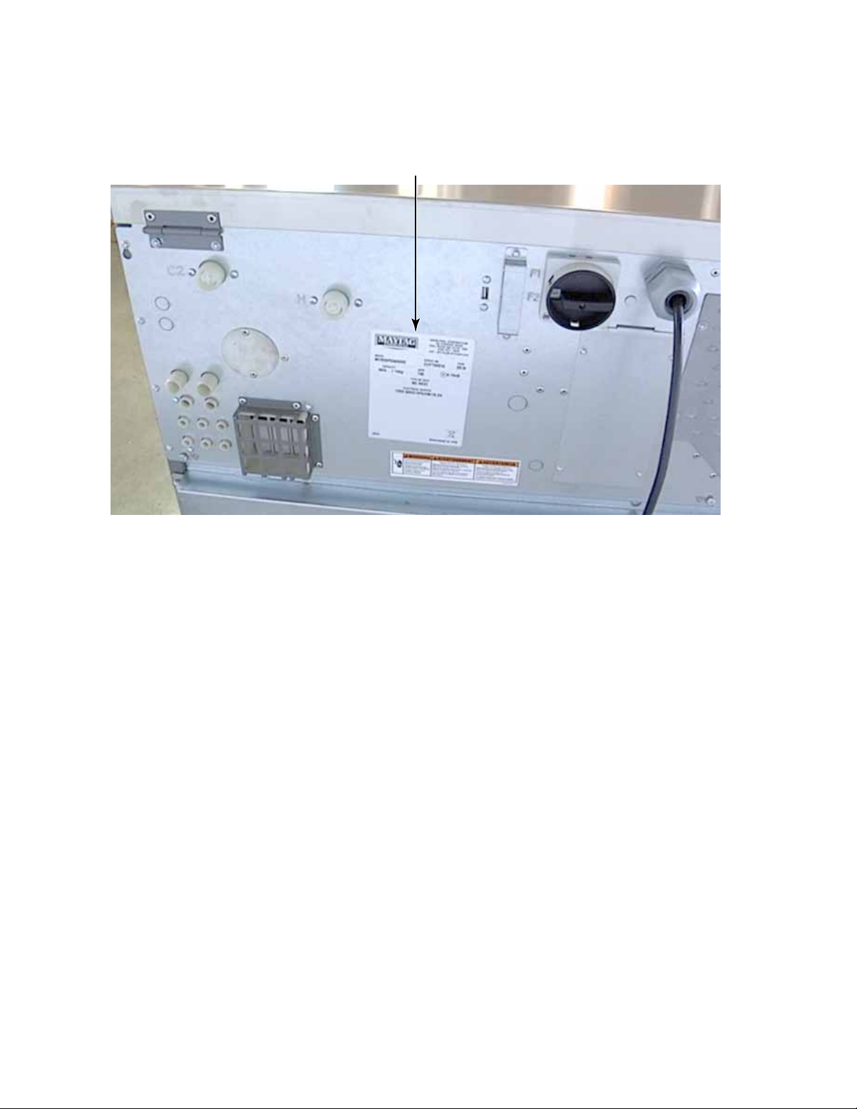
Data plate location ............................................................................................................ 1-4
Warranty for vended product ............................................................................................ 1-5
Warranty for on-premise product ...................................................................................... 1-6
INFORMATION & SPECIFICATIONS....................................................................................... 2-1
Rigid model dimensions.................................................................................................... 2-1
Specications.................................................................................................................... 2-2
Bolt torque values ............................................................................................................. 2-6
BASIC OPERATION ................................................................................................................. 3-1
Power................................................................................................................................ 3-1
Door lock........................................................................................................................... 3-1
Water inlet valves.............................................................................................................. 3-2
USB update procedure .....................................................................................................3-3
Chemical injection............................................................................................................. 3-3
Washer maintenance........................................................................................................ 3-4
Belt inspection and adjustment......................................................................................... 3-5
COMPONENT ACCESS ........................................................................................................... 4-1
Top panel open ................................................................................................................. 4-1
Components accessible under the top panel.................................................................... 4-2
Chemical dispenser assembly .......................................................................................... 4-3
Top panel lock................................................................................................................... 4-5
Top panel removal ............................................................................................................4-6
EMI lter............................................................................................................................ 4-7
Drive contactor.................................................................................................................. 4-8
Supply power transformer................................................................................................. 4-9
Supply power switch ......................................................................................................... 4-10
Fuse replace ..................................................................................................................... 4-11
Soap signal board............................................................................................................. 4-12
Variable frequency drive ................................................................................................... 4-13
Water inlet valve repair ..................................................................................................... 4-15
Water inlet valve removal.................................................................................................. 4-16
Control panel open ........................................................................................................... 4-18
Emergency stop button..................................................................................................... 4-19
Coin drop .......................................................................................................................... 4-20
HMI - connections............................................................................................................. 4-21
Human machine interface - removal................................................................................. 4-22
Appliance control unit - ACU - connections ...................................................................... 4-23
Appliance control unit - removal ....................................................................................... 4-24
Wi module ....................................................................................................................... 4-25

iv
TABLE OF CONTENTS - CONTINUED
Page
Service switch................................................................................................................... 4-26
Door handle ...................................................................................................................... 4-27
Door strike ........................................................................................................................ 4-27
Door and Door hinges....................................................................................................... 4-28
Door glass......................................................................................................................... 4-29
Toe panel .......................................................................................................................... 4-30
Drain valve........................................................................................................................ 4-31
Front panel........................................................................................................................ 4-32
Door lock........................................................................................................................... 4-33
Heating elements.............................................................................................................. 4-34
Ornament panel ................................................................................................................ 4-35
Back panel ........................................................................................................................ 4-36
Lower back panel.............................................................................................................. 4-37
Drive belt........................................................................................................................... 4-38
Temperature sensor.......................................................................................................... 4-38
Speed sensor.................................................................................................................... 4-39
Drive motor ....................................................................................................................... 4-40
Bearing housing................................................................................................................ 4-41
Bearing and basket replacement - Preferred method....................................................... 4-44
COMPONENT TESTING........................................................................................................... 5-1
Component resistance values .......................................................................................... 5-1
Door lock........................................................................................................................... 5-2
Variable frequency drive ................................................................................................... 5-4
Variable frequency drive wiring......................................................................................... 5-6
Drive contactor.................................................................................................................. 5-7
Coin drop acceptor ........................................................................................................... 5-8
DIAGNOSIS AND TROUBLESHOOTING ................................................................................ 6-1
Service diagnostics........................................................................................................... 6-1
Diagnostic cycle chart....................................................................................................... 6-2
Error codes ....................................................................................................................... 6-3
WIRING DIAGRAM................................................................................................................... 7-1
Single phase ..................................................................................................................... 7-1
ALPHABETICAL COMPONENT INDEX .................................................................................. 7-3

v
INTERACTIVE SERVICE MANUAL INSTRUCTIONS
View on PC, MAC, iPad, iPhone and Android devices.
Acrobat Reader is available for all devices to open .pdf documents.
Click on any topic in the Table of Contents to go directly to that section.
Click on any link that says (See page ?-?) to go directly to the page referenced.
Click to view the video procedure on YouTube.
VIEW EQUIPMENT & SAFETY VIDEO

vi
---- NOTES ----

1-1
GENERAL
IMPORTANT
Electrostatic Discharge (ESD)
Sensitive Electronics
ESD problems are present everywhere. ESD may damage or weaken
the electronic control assembly. The new control assembly may appear
to work well after repair is nished, but failure may occur at a later date
due to ESD stress.
• Use an anti-static wrist strap. Connect wrist strap to green ground
connection point or unpainted metal in the appliance
-OR-
Touch your nger repeatedly to a green ground connection point or
unpainted metal in the appliance.
• Before removing the part from its package, touch the anti-static bag
to a green ground connection point or unpainted metal in the
appliance.
• Avoid touching electronic parts or terminal contacts; handle
electronic control assembly by edges only.
• When repackaging failed electronic control assembly in anti-static
bag, observe above instructions.
WASHER SAFETY

1-2
MODEL NUMBER DESIGNATIONS
MODEL NUMBER M YR 30 PD W 0 0 0 0
BRAND
M Maytag
MOUNTING TYPE
YR Rigid Mount
YS Soft Mount
DRY WEIGHT CAPACITY
20 20 lbs / 9.1 kg
25 25 lbs / 11.4 kg
30 30 lbs / 13.6 kg
40 40 lbs / 18.2 kg
55 55 lbs / 25 kg
65 65 lbs / 29.5 kg
PAYMENT METHOD / CONTROL TYPE
PR Card Reader Ready
PD Single Coin Drop Mechanism (US$0.25)
PE Dual Coin Drop Mechanism (CA$0.25/CA$1.00)
PF Electronic Coin Drop Mechanism
PN OPL Control (no payment system)
ELECTRIC POWER CONNECTION
W 120V / 60Hz / 1-Phase (Non-IEC, no electric heat)
T 208-240V / 50/60Hz / 1 Phase (Non-IEC, no electric heat)
S 220-240V / 50/60Hz / 1 Phase (Non-IEC, no electric heat)
V 220-240V / 50/60Hz / 3 Phase (IEC)
N 380-415V / 50/60Hz / 3 Phase (IEC)
R 440-480V / 50/60Hz / 3 Phase (IEC)
ELECTRIC HEAT OPTION CODE
0 No Internal Heating
1 8 kW
2 12 kW
3 16 kW
4 18 kW
PANEL MATERIAL / COLOR OPTION CODE
0 Painted Sides, Stainless Fronts
1 Stainless Sides and Front
EXTERNAL CHEMICAL SIGNAL OPTION CODE
0 No
1 Yes
WATER INLET & DRAIN OPTION CODE
0 2 Inlets & 1 Drain 2 2 Inlets & 2 Drains
1 3 Inlets & 1 Drain 3 3 Inlets & 2 Drains

1-3
SERIAL NUMBER DESIGNATIONS
SERIAL NUMBER MC 7 35 109
DIVISION RESPONSIBILITY
MC Fall River, MA
YEAR OF PRODUCTION
7 2017
8 2018
9 2019
WEEK OF PRODUCTION
35 35th Week in the calendar year
MANUFACTURING SEQUENCE NUMBER

1-4
DATA PLATE LOCATION
Data Plate On Back Panel

1-5
WARRANTY FOR VENDED PRODUCT
26
MAYTAG COMMERCIAL LAUNDRY® WARRANTY
FOR VENDED PRODUCT MULTI-LOAD WASHERS
MYR20, MYR25, MYR30, MYR40, MYR55, MYR65
1. All other costs including labor, transportation, shipping, or custom duties
for covered parts.
2. Factory specified replacement parts if this commercial appliance is
used for other than normal, commercial use or when it is used in a manner
that is inconsistent to published user or operator instructions and/or
installation instructions.
3. Service calls to correct the installation of your commercial appliance,
to instruct you on how to use your commercial appliance, to replace
or repair house fuses, or to correct external wiring or plumbing.
4. Service calls to repair or replace appliance light bulbs, air filters, or water
filters. Consumable parts are excluded from warranty coverage.
5. Damage resulting from improper handling of product during delivery, theft,
accident, alteration, misuse, abuse, fire, flood, acts of God, improper
installation, installation not in accordance with local electrical or plumbing
codes, or use of products not approved by Maytag.
6. Pick up and delivery. This commercial appliance is designed to be
repaired on location.
7. Repairs to parts or systems resulting from unauthorized modifications
made to the commercial appliance.
8. The removal and reinstallation of your commercial appliance if it is
installed in an inaccessible location or is not installed in accordance
with published installation instructions.
9. Damage resulting from exposure to chemicals.
10. Changes to the building, room, or location needed in order to make the
commercial appliance operate correctly.
11. Factory specified replacement parts on commercial appliances with
original model/serial numbers that have been removed, altered, or cannot
be easily determined.
12. Discoloration, rust, or oxidation of stainless steel surfaces.
13. Factory specified replacement parts as a result of incorrect diagnosis
or repair by an “unauthorized” service company.
14. Replacement parts during the sixth through tenth years from the date of
original purchase where the commercial appliance is installed, operated
and maintained in a setting other than a vended and/or multi-housing
environment.
15. Replacement parts during the sixth through tenth years from the
date of original purchase where the defective part is not preventing the
functioning of the product.
The cost of repair or replacement under these excluded circumstances
shall be borne by the customer.
FIVE YEAR LIMITED WARRANTY
(PARTS ONLY — LABOR NOT INCLUDED)
For the first five years from the original date of purchase,
when this commercial appliance is installed, operated, and
maintained according to the instructions attached to or
furnished with the product, Maytag brand of Whirlpool
Corporation (hereafter “Maytag”) will pay for factory specified
replacement parts to correct defects in materials or
workmanship that existed when this commercial appliance
was purchased. This limited warranty does not include labor.
SIXTH THROUGH TENTH YEAR LIMITED WARRANTY
(CERTAIN COMPONENT PARTS ONLY –
LABOR NOT INCLUDED)
In the sixth through tenth years from the date of original
purchase, when this commercial appliance is installed,
operated, and maintained according to instructions attached
to or furnished with the product, Maytag will pay for factory
specified replacement parts for the following components to
correct non-cosmetic defects in materials or workmanship in
the part that prevent function of the product and that existed
when this commercial appliance was purchased. This is a
limited 10-year warranty on the below named parts only and
does not include labor.
Outer shell, Drum and shaft assembly, Inner welded frame,
Bearings and seals.
YOUR SOLE AND EXCLUSIVE REMEDY UNDER THIS
LIMITED WARRANTY SHALL BE PART REPLACEMENT AS
PROVIDED HEREIN. Maytag recommends that you use an “in
network” service provider to diagnose and repair your
Commercial Laundry product. Maytag will not be responsible
under this warranty to provide additional replacement parts as
a result of incorrect diagnosis or repair by an “out of network”
service company. This limited warranty is valid in the United
States or Canada and applies only when the commercial
appliance is used in the country in which it was purchased.
This limited warranty is effective from the date of the original
consumer purchase. Proof of original purchase date is
required to obtain service under this limited warranty.
DISCLAIMER OF IMPLIED WARRANTIES
IMPLIED WARRANTIES, INCLUDING ANY IMPLIED WARRANTY OF MERCHANTABILITY OR IMPLIED WARRANTY OF FITNESS FOR A
PARTICULAR PURPOSE, ARE LIMITED TO ONE YEAR OR THE SHORTEST PERIOD ALLOWED BY LAW. Some states and provinces do
not allow limitations on the duration of implied warranties of merchantability or fitness, so this limitation may not apply to you. This warranty
gives you specific legal rights, and you also may have other rights that vary from state to state or province to province.
LIMITATION OF REMEDIES; EXCLUSION OF INCIDENTAL AND CONSEQUENTIAL DAMAGES
YOUR SOLE AND EXCLUSIVE REMEDY UNDER THIS LIMITED WARRANTY SHALL BE PART REPLACEMENT AS PROVIDED HEREIN.
MAYTAG SHALL NOT BE LIABLE FOR INCIDENTAL OR CONSEQUENTIAL DAMAGES. Some states and provinces do not allow the exclusion
or limitation of incidental or consequential damages, so these limitations and exclusions may not apply to you. This warranty gives you
specific legal rights, and you also may have other rights that vary from state to state or province to province.
DISCLAIMER OF REPRESENTATIONS OUTSIDE OF WARRANTY
Maytag makes no representations about the quality, durability, or need for service or repair of this commercial appliance other than the
representations contained in this warranty. If you want a longer or more comprehensive warranty than the limited warranty that comes with
this commercial appliance, you should ask Maytag or your retailer about buying an extended warranty.
07/18
TEN YEAR LIMITED WARRANTY
WHAT IS COVERED WHAT IS NOT COVERED
IF YOU NEED SERVICE:
Contact your authorized Maytag Commercial Laundry
®
distributor.
To locate your authorized Maytag Commercial Laundry
®
distributor,
call 1-800-662-3587, or for web inquiries, visit
www.MaytagCommercialLaundry.com.
For written correspondence:
Maytag Commercial Laundry
®
Service Department
2000 N M 63
Benton Harbor, Michigan 49022-2632 USA

1-6
27
MAYTAG COMMERCIAL LAUNDRY® WARRANTY
FOR ON-PREMISE PRODUCT MULTI-LOAD WASHERS
MYR20, MYR25, MYR30, MYR40, MYR55, MYR65
1. All other costs including labor, transportation, shipping, or custom duties
for covered parts.
2. Factory specified replacement parts if this commercial appliance is
used for other than normal, commercial use or when it is used in a manner
that is inconsistent to published user or operator instructions and/or
installation instructions.
3. Service calls to correct the installation of your commercial appliance,
to instruct you on how to use your commercial appliance, to replace
or repair house fuses, or to correct external wiring or plumbing.
4. Service calls to repair or replace appliance light bulbs, air filters, or water
filters. Consumable parts are excluded from warranty coverage.
5. Damage resulting from improper handling of product during delivery, theft,
accident, alteration, misuse, abuse, fire, flood, acts of God, improper
installation, installation not in accordance with local electrical or plumbing
codes, or use of products not approved by Maytag.
6. Pick up and delivery. This commercial appliance is designed to be repaired
on location.
7. Repairs to parts or systems resulting from unauthorized modifications
made to the commercial appliance.
8. The removal and reinstallation of your commercial appliance if it is installed
in an inaccessible location or is not installed in accordance
with published installation instructions.
9. Damage resulting from exposure to chemicals.
10. Changes to the building, room, or location needed in order to make the
commercial appliance operate correctly.
11. Factory specified replacement parts on commercial appliances with
original model/serial numbers that have been removed, altered, or cannot
be easily determined.
12. Discoloration, rust, or oxidation of stainless steel surfaces.
13. Factory specified replacement parts as a result of incorrect diagnosis
or repair by an “unauthorized” service company.
14. Replacement parts during the Forth and Fifth years from the date of
original purchase where the commercial appliance is installed, operated
and maintained in a setting other than a vended and/or multi-housing
environment.
15. Replacement parts during the Forth and Fifth years from the
date of original purchase where the defective part is not preventing the
functioning of the product.
The cost of repair or replacement under these excluded circumstances
shall be borne by the customer.
THREE YEAR LIMITED WARRANTY
(PARTS ONLY — LABOR NOT INCLUDED)
For the first Three years from the original date of purchase,
when this commercial appliance is installed, operated, and
maintained according to the instructions attached to or
furnished with the product, Maytag brand of Whirlpool
Corporation (hereafter “Maytag”) will pay for factory specified
replacement parts to correct defects in materials or
workmanship that existed when this commercial appliance
was purchased. This limited warranty does not include labor.
FORTH AND FIFTH YEAR LIMITED WARRANTY
(CERTAIN COMPONENT PARTS ONLY –
LABOR NOT INCLUDED)
In the Forth and Fifth years from the date of original purchase,
when this commercial appliance is installed, operated, and
maintained according to instructions attached to or furnished
with the product, Maytag will pay for factory specified
replacement parts for the following components to correct
non-cosmetic defects in materials or workmanship in the part
that prevent function of the product and that existed when
this commercial appliance was purchased. This is a limited
5-year warranty on the below named parts only and does not
include labor.
Outer shell, Drum and shaft assembly, Inner welded frame,
Bearings and seals.
YOUR SOLE AND EXCLUSIVE REMEDY UNDER THIS
LIMITED WARRANTY SHALL BE PART REPLACEMENT AS
PROVIDED HEREIN. Maytag recommends that you use an “in
network” service provider to diagnose and repair your
Commercial Laundry product. Maytag will not be responsible
under this warranty to provide additional replacement parts
as a result of incorrect diagnosis or repair by an “out of
network” service company. This limited warranty is valid in
the United States or Canada and applies only when the
commercial appliance is used in the country in which it was
purchased. This limited warranty is effective from the date of
the original consumer purchase. Proof of original purchase
date is required to obtain service under this limited warranty.
DISCLAIMER OF IMPLIED WARRANTIES
IMPLIED WARRANTIES, INCLUDING ANY IMPLIED WARRANTY OF MERCHANTABILITY OR IMPLIED WARRANTY OF FITNESS FOR A
PARTICULAR PURPOSE, ARE LIMITED TO ONE YEAR OR THE SHORTEST PERIOD ALLOWED BY LAW. Some states and provinces do
not allow limitations on the duration of implied warranties of merchantability or fitness, so this limitation may not apply to you. This warranty
gives you specific legal rights, and you also may have other rights that vary from state to state or province to province.
LIMITATION OF REMEDIES; EXCLUSION OF INCIDENTAL AND CONSEQUENTIAL DAMAGES
YOUR SOLE AND EXCLUSIVE REMEDY UNDER THIS LIMITED WARRANTY SHALL BE PART REPLACEMENT AS PROVIDED HEREIN.
MAYTAG SHALL NOT BE LIABLE FOR INCIDENTAL OR CONSEQUENTIAL DAMAGES. Some states and provinces do not allow the exclusion
or limitation of incidental or consequential damages, so these limitations and exclusions may not apply to you. This warranty gives you
specific legal rights, and you also may have other rights that vary from state to state or province to province.
DISCLAIMER OF REPRESENTATIONS OUTSIDE OF WARRANTY
Maytag makes no representations about the quality, durability, or need for service or repair of this commercial appliance other than the
representations contained in this warranty. If you want a longer or more comprehensive warranty than the limited warranty that comes with
this commercial appliance, you should ask Maytag or your retailer about buying an extended warranty.
07/18
FIVE YEAR LIMITED WARRANTY
WHAT IS COVERED WHAT IS NOT COVERED
IF YOU NEED SERVICE:
Contact your authorized Maytag Commercial Laundry
®
distributor.
To locate your authorized Maytag Commercial Laundry
®
distributor,
call 1-800-662-3587, or for web inquiries, visit
www.MaytagCommercialLaundry.com.
For written correspondence:
Maytag Commercial Laundry
®
Service Department
2000 N M 63
Benton Harbor, Michigan 49022-2632 USA
WARRANTY FOR ON-PREMISE PRODUCT

2-1
INFORMATION & SPECIFICATIONS
RIGID MODEL DIMENSIONS

2-2
SPECIFICATIONS
4
SPECIFICATIONS
Model Cylinder Volume
Liters (cu. ft.)
Cylinder diameter
mm (in.)
Cylinder depth
mm (in.)
Dry load
capacity kg (lb)
Max. spin
RPM
Max. extract
force (G-force)
MYR20 78 (2.74) 530 (20.9) 352 (13.9) 9 (20) 838 200
MYR25 108 (3.76) 620 (24.4) 352 (13.9) 11 (25) 790 200
MYR30 138 (4.86) 620 (24.4) 454 (17.9) 14 (30) 790 200
MYR40 183 (6.45) 750 (29.5) 411 (16.2) 18 (40) 693 200
MYR55 242 (8.56) 750 (29.5) 548 (21.6) 25 (55) 693 200
MYR65 276 (9.76) 750 (29.5) 621 (24.4) 30 (65) 693 200
Dimensions
Washer Dimensions
B
C
D
A
A B C D
Model Width
mm (in.)
Door
Opening
mm (in.)
Depth
mm (in.)
Height
mm (in.)
MYR20 660 (26) 328 (12.9) 686 (27) 1112 (43.8)
MYR25 750 (29.5) 410 (16.1) 725 (28.5) 1222 (48.1)
MYR30 750 (29.5) 410 (16.1) 840 (33.1) 1222 (48.1)
MYR40 890 (35.0) 459 (18.1) 876 (34.5) 1410 (55.5)
MYR55 890 (35.0) 459 (18.1) 1011 (39.8) 1410 (55.5)
MYR65 890 (35.0) 459 (18.1) 1085 (42.7) 1410 (55.5)

2-3
5
SPECIFICATIONS
Dimensions
Washer Rear Dimensions MYR20 MYR25 MYR30 MYR40 MYR55 MYR65
N1
mm
(in.)
45
(1.8)
41
(1.6)
41
(1.6)
45
(1.8)
45
(1.8)
45
(1.8)
M2
mm
(in.)
95
(3.7)
95
(3.7)
95
(3.7)
133
(5.2)
133
(5.2)
133
(5.2)
M1
mm
(in.)
168
(6.6)
213
(8.4)
213
(8.4)
283
(11.1)
283
(11.1)
283
(11.1)
Q2
mm
(in.)
1019
(40.1)
1130
(44.5)
1130
(44.5)
1317
(51.8)
1317
(51.8)
1317
(51.8)
R3
mm
(in.)
1019
(40.1)
1130
(44.5)
1130
(44.5)
1318
(51.8)
1318
(51.8)
1318
(51.8)
P2
mm
(in.)
1032
(42.6)
1140
(44.9)
1140
(44.9)
1330
(52.3)
1330
(52.3)
1330
(52.3)
I2
mm
(in.)
1045
(41.1)
1156
(45.5)
1156
(45.5)
1343
(52.8)
1343
(52.8)
1343
(52.8)
K1
mm
(in.)
101
(4.0)
101
(4.0)
101
(4.0)
175
(6.8)
175
(6.8)
175
(6.8)
L1
mm
(in.)
146
(5.7)
146
(5.7)
146
(5.7)
175
(6.8)
175
(6.8)
175
(6.8)
J1
mm
(in.)
225
(8.8)
225
(8.8)
225
(8.8)
289
(11.4)
289
(11.4)
289
(11.4)
Q1
mm
(in.)
280
(11)
371
(14.6)
371
(14.6)
406
(16.0)
406
(16.0)
406
(16.0)
R1
mm
(in.)
305
(12)
394
(15.5)
394
(15.5)
429
(16.8)
429
(16.8)
429
(16.8)
P1
mm
(in.)
368
(14.5)
458
(18)
458
(18)
492
(19.4)
492
(19.4)
492
(19.4)
I1
mm
(in.)
451
(17.7)
543
(21.4)
543
(21.4)
578
(22.7)
578
(22.7)
578
(22.7)
O1
mm
(in.)
60
(2.3)
70
(2.7)
70
(2.7)
70
(2.7)
70
(2.7)
70
(2.7)
R2
K1
L1
J1
I1
R1
Q1
P1
01
K2
J2
L2
R3
P2
I2
O2
N2
M2
N1
M1
M3
Q2
MYR20 MYR25 MYR30 MYR40 MYR55 MYR65
R2
mm
(in.)
1054
(41.5)
1155
(45.5)
1155
(45.5)
1343
(52.9)
1343
(52.9)
1343
(52.9)
K2
mm
(in.)
1023
(40.3)
1133
(44.6)
1133
(44.6)
1321
(52)
1321
(52)
1321
(52)
J2
mm
(in.)
1000
(39.4)
1108
(43.6)
1108
(43.6)
1224
(48.2)
1224
(48.2)
1224
(48.2)
L2
mm
(in.)
927
(36.5)
1035
(40.8)
1035
(40.8)
1224
(48.2)
1224
(48.2)
1224
(48.2)
O2
mm
(in.)
826
(32.5)
937
(36.9)
937
(36.9)
1095
(43.1)
1095
(43.1)
1095
(43.1)
N2
mm
(in.)
372
(14.6)
537
(21.1)
537
(21.1)
534
(21)
534
(21)
534
(21)

2-4
6
SPECIFICATIONS
Dimensions
Crated Dimensions
Model Crated Width
mm (in.)
Crated Depth
mm (in.)
Crated Height
mm (in.)
MYR20 705 (27.8) 841 (33.1) 1270 (50.0)
MYR25 800 (31.5) 880 (34.6) 1381 (54.4)
MYR30 800 (31.5) 991 (39.0) 1381 (54.4)
MYR40 940 (37.0) 1029 (40.5) 1560 (61.43)
MYR55 940 (37.0) 1169 (46.0) 1560 (61.4)
MYR65 940 (37.0) 1242 (48.9) 1560 (61.4)
Approximate Weight
Model Uncrated-kg (lb) Crated-kg (lb)
MYR20 151 (334) 166 (365)
MYR25 203 (447) 218 (480)
MYR30 222 (489) 237 (523)
MYR40 312 (688) 328 (724)
MYR55 332 (731) 349 (769)
MYR65 347 (764) 364 (802)
Water Heating (Factory Option Only)
Model Electrical heating, optional alternate heating
element size-kW
MYR20 8 or 12
MYR25 8 or 12
MYR30 8 or 12
MYR40 16
MYR55 18
MYR65 18

2-5
7
SPECIFICATIONS
Water, Drain, External Supply Connections
Model
Number
of water
inlets
Optional
third
water inlet
Inlet sizes
mm (in.)
Operating
Pressure
Bar (Psi)
Number of
dispenser
compartments
External
chemical
connections,
number
Drain valve
drain, Size
mm (in.)
Optional
Second
Drain Valve
MYR20 2 Yes 13 (1/2") 1-8 (20-120) 4 8 76 (3) NO
MYR25 2 Yes 13 (1/2") 1-8 (20-120) 4 8 76 (3) NO
MYR30 2 Yes 13 (1/2") 1-8 (20-120) 4 8 76 (3) NO
MYR40 2 Yes 13 (1/2") 1-8 (20-120) 4 8 76 (3) NO
MYR55 2 Yes 13 (1/2") 1-8 (20-120) 4 8 76 (3) YES
MYR65 2 Yes 13 (1/2") 1-8 (20-120) 4 8 76 (3) YES
Energy/Water Usage
Model
Average Cycle Water Use
lbs Hot
Water
Total
Water
Total/Hot
Ratio
MYR20 20 4 11.7 2.925
MYR25 25 6 17.6 2.925
MYR30 30 8 23.4 2.925
MYR40 40 11 32.2 2.925
MYR55 55 14 41.0 2.925
MYR65 65 17 49.7 2.925
Gallons

2-6
BOLT TORQUE VALUES
IMPORTANT: Replace a damaged bolt with a bolt of the same strength value marked on its head.
Standard torques are used, except in the locations specied below:
Component MYR25 - MYR30 MYR40 - MYR55 - MYR65
Ft Lbs NM Ft Lbs NM
Tub Cover
Clamp
9 12 9 12
Tub Strap 18 25 18 25
Drive Pulley 37 50 74 100
Bearing
Housing
18 25 52 70
Crosspiece
(Outer Bolts)
37 50 70 95
Crosspiece
(Inner Bolts)
15 21 18 25

3-1
BASIC OPERATION
Power supply voltage initiates at the power
disconnect switch mounted to the upper back
panel and ows through the line lter to the
controls transformer and drive contactor. The
controls transformer provides 220VAC to the
ACU and to the liquid supply board. Protection
is provided by 1amp fuses. The drive
contactor supplies line voltage to the VFD only
when cycle is initiated or in diagnostic test
mode.
The door lock assembly is non-serviceable
and only replaceable as a complete
component. There are three internal switches
to providing lock status to the ACU. With
the washer idle and the door open, the door
detection and door locked switches will be
in an open state and the door unlocked
switch closed. When the door is closed with
the door pin making initial insertion into the
lock assembly the door detection switch will
change from open to closed. The door lock
switch remains open and the door unlock
switch remains closed. When a cycle is
initiated, the ACU will provide 12VDC to the
door lock motor and pull the door into a locked
position. This will change the door locked
switch to closed and door unlocked switch to
open. The door detection switch will remain
closed.
POWER DOOR LOCK

3-2
The Hot and Cold inlet Valves are mounted
to the top right side of the upper back panel.
The Cold inlet is a four way valve and the Hot
inlet is a three way valve. See Inlets Valve
Chart, below, for Dispenser connections.
Each port will ll at approximately 20 liters per
minute. Valve Coils are 220 VAC.
(See page 4-17) for proper connection of
each water inlet valve.
Valve # Water Temp Dispenser
1 Cold PreWash
2 Cold Main Wash
3 Cold Bleach
4 Cold Fabric Softener
5 Hot PreWash
6 Hot Main Wash
7 Hot Bleach
The inlet valves are designed to operate over
a water pressure range of 30 to 120 pounds
per square inch. Low water pressure and
particularly low ow pressure may result in a
valve not closing properly. Debris in the water
line may also affect operation of the valves.
NOTE: Less than 20 psi, valves may leak.
The rst time the washer is hooked up and
the water is turned on, there will be a small
amount of water released through the valve(s)
as the water line pressure builds up behind
the rubber diaphragm(s) in the guide tube of
the valve(s). It is this internal pressure that
keeps the diaphragm seated against the valve
seat and avoids water ow through the valve.
The water at the inlet (G) pushes against the
diaphragm (H). The solenoid plunger (B) and
the spring (A) by themselves are not strong
enough to overcome the water pressure
trying to raise the diaphragm. Therefore, it is
necessary to equalize the pressure on both
sides of the diaphragm in order to keep the
diaphragm in a closed position. Pressure
builds up in the guide tube above the
diaphragm and keeps it in the closed position.
The ow of water is blocked until the solenoid
is energized. To accomplish this, a small pilot
hole (C) is provided in the diaphragm to allow
water to ow into the plunger area. The water
in the plunger area equalizes the pressure
on both sides of the diaphragm. The spring
pushes the plunger down into the center
hole (D) of the diaphragm and closes it until
the solenoid is energized. To energize the
solenoid an electromagnetic eld is created
that pulls the plunger upwards, which opens
the center hole. Water is allowed to escape
through the center hole in the diaphragm,
reducing the pressure in the plunger area.
The pressure from the water supply forces the
diaphragm up and allows the water to pass
under the diaphragm and into the washer.
WATER INLET VALVES
Other manuals for MYR20
1
This manual suits for next models
5
Table of contents
Other Maytag Commercial Washer manuals

Maytag Commercial
Maytag Commercial MAT20PDFGW User manual

Maytag Commercial
Maytag Commercial MAT20PDFGW User manual

Maytag Commercial
Maytag Commercial MYR20 User manual

Maytag Commercial
Maytag Commercial MHN30PD User manual

Maytag Commercial
Maytag Commercial MAT20MNAGW User manual

Maytag Commercial
Maytag Commercial MVWP586GW User manual

Maytag Commercial
Maytag Commercial MAT20PDAGW User manual

Maytag Commercial
Maytag Commercial MVWP576KW0 User manual

Maytag Commercial
Maytag Commercial MVWP575GW User manual

Maytag Commercial
Maytag Commercial MHN33PD User manual