Maytronics ecoclear EC 12KW User manual

Inverter Heat Pump
Installation
& Operation
Manual
EC 12KW
EC 16KW
EC 20KW
EC 24KW
Should the installer or owner be unfamiliar with the correct installation or operation
of this type of equipment, you should contact the distributor/manufacturer for the
correct advice before proceeding with the installation or operation of this product.
The equipment operator or owner must be provided with this owner’s manual.
Manufactured by

2Inverter Heat Pump Owner’s Manual
CUSTOMER SERVICE / TECHNICAL SUPPORT
If you have questions about ordering Maytronics Ecoclear® replacement parts, and pool prod-
ucts, please contact:
Head Oce: Brisbane, Queensland
Address: 2/91 Rudd Street (entry o Boundary Road), Oxley QLD 4075
Phone Number: 1300 693 657
Email: infoau@maytronics.com
Support Contact

3
Inverter Heat Pump Owner’s Manual
Notices and Warnings����������������������������������������������������������������������������������������������������������������������������4
Ecoclear® Contents and Overview ������������������������������������������������������������������������������������������������������6
Ecoclear® Inverter Heat Pump Package Contents ......................................................................................................................................6
Ecoclear® Inverter Heat Pump Overview........................................................................................................................................................6
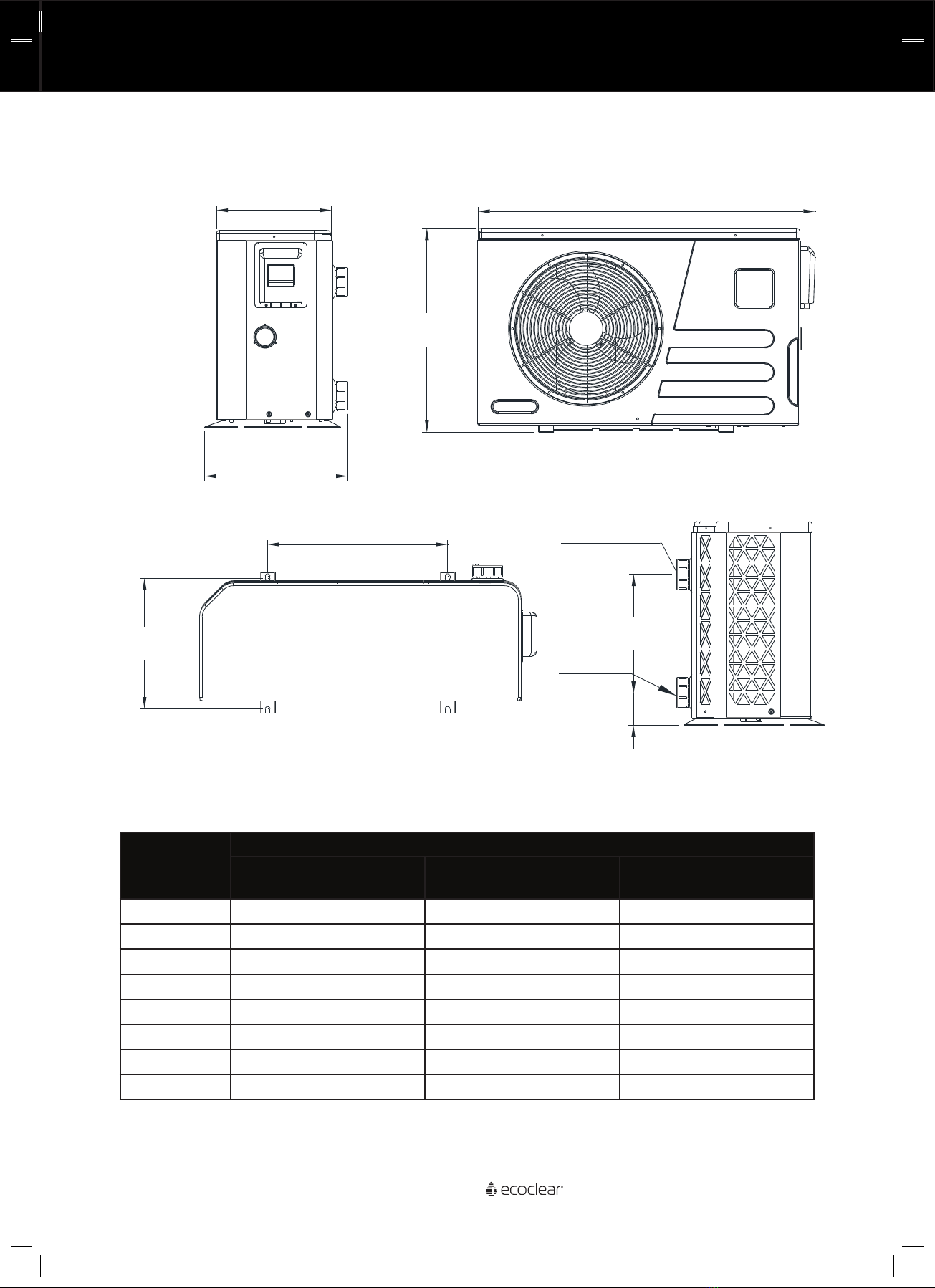
Dimensions & Specifications ���������������������������������������������������������������������������������������������������������������� 7
Dimensions .................................................................................................................................................................................................................. 7
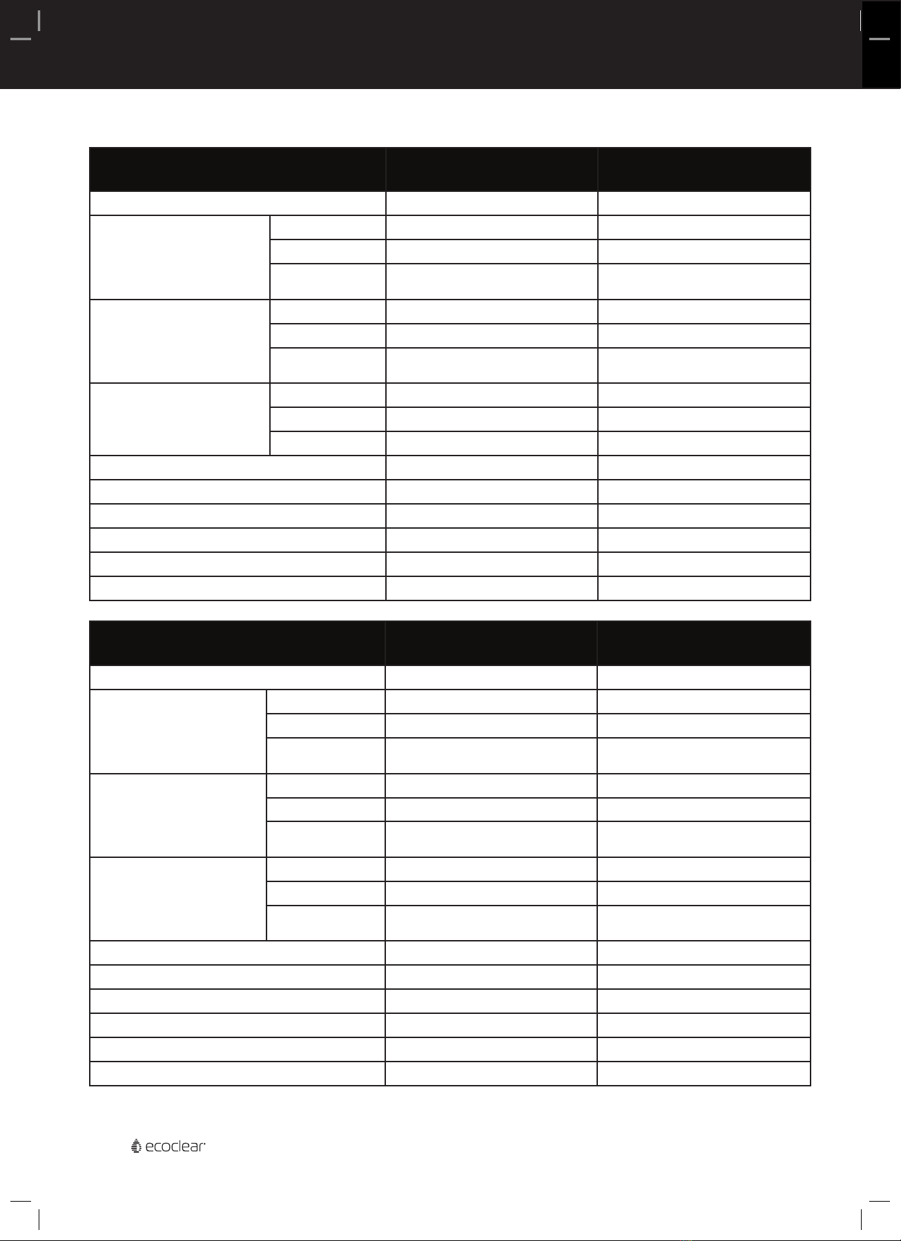
Specifications ..............................................................................................................................................................................................................8
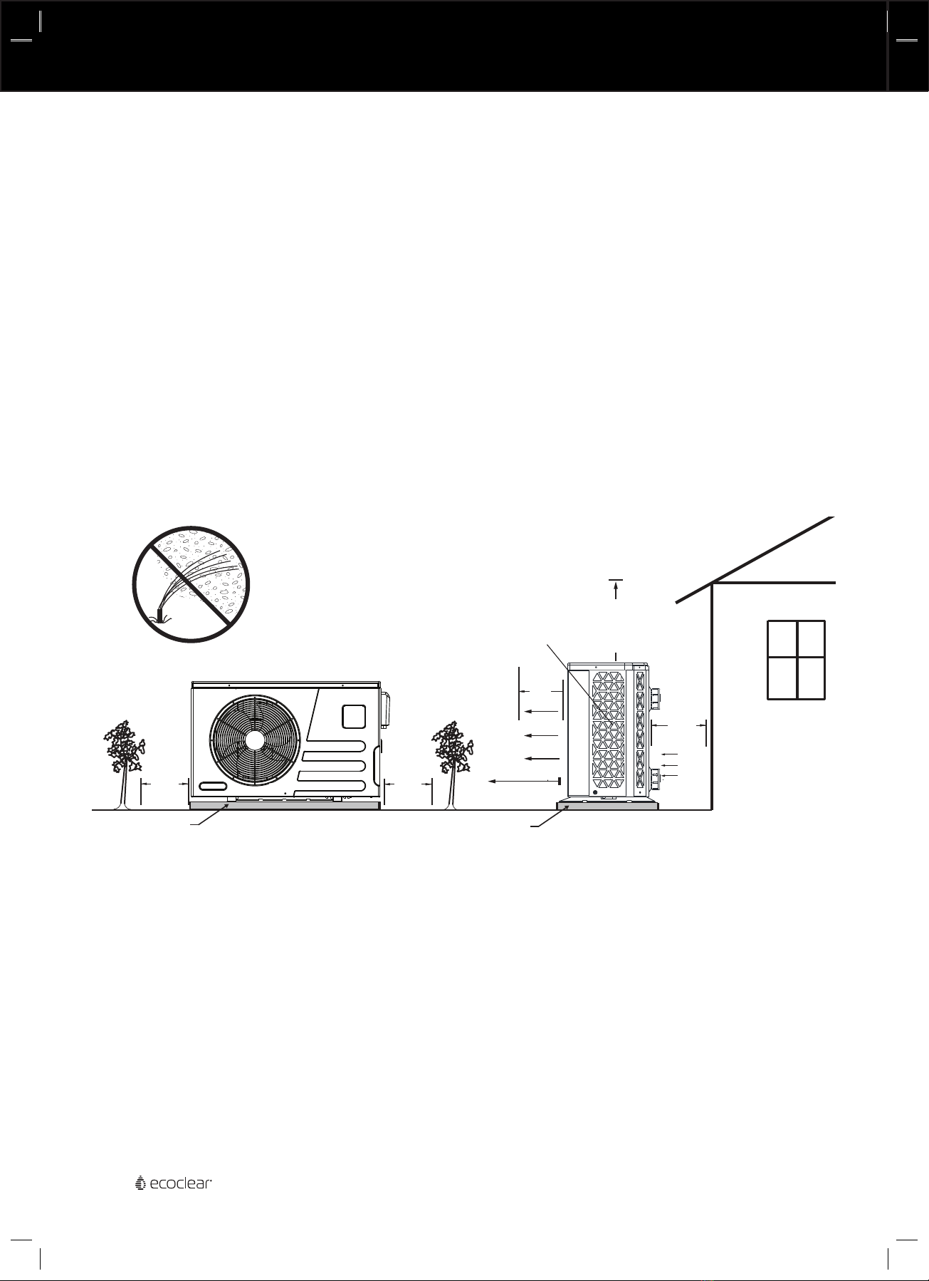
Installation����������������������������������������������������������������������������������������������������������������������������������������������9
Location and Clearances......................................................................................................................................................................................10
Anchor Clamp Installation ...................................................................................................................................................................................10
Water Connections to the Heat Pump............................................................................................................................................................ 11
Plumbing Connections - Standard................................................................................................................................................................... 12
Plumbing Connections - Separate Circulation System............................................................................................................................ 13
Multiple Heater Type Installation ..................................................................................................................................................................... 14
Multiple Heat Pump Installation....................................................................................................................................................................... 14
Electrical Connections ��������������������������������������������������������������������������������������������������������������������������15
General Information............................................................................................................................................................................................... 15
Equipotential Bonding........................................................................................................................................................................................... 15
Main Power................................................................................................................................................................................................................ 15
Configuration�����������������������������������������������������������������������������������������������������������������������������������������17
Control Panel..............................................................................................................................................................................................................17
Setting the Clock...................................................................................................................................................................................................... 19
Setting the On/O Timer ..................................................................................................................................................................................... 21
Setting the Mute Timer ........................................................................................................................................................................................ 21
Menu / Setting Parameters................................................................................................................................................................................ 21
Forced Defrost Mode............................................................................................................................................................................................. 21
Turning Heat Pump On and O........................................................................................................................................................................ 20
Setting the Temperature and Mode .............................................................................................................................................................. 20
Status Query..............................................................................................................................................................................................................22
Scenario (Operating Mode) ................................................................................................................................................................................ 23
Connecting the Heat Pump to Automation���������������������������������������������������������������������������������������24
Pool/Spa Heating Combinations (Recommended Configurations) ................................................................................................. 24
Maintenance & Troubleshooting ��������������������������������������������������������������������������������������������������������26
Water Chemistry..................................................................................................................................................................................................... 26
Inspection and Service ........................................................................................................................................................................................ 26
Owner Inspection................................................................................................................................................................................................... 26
Professional Maintenance and Service.........................................................................................................................................................27
Winterising .................................................................................................................................................................................................................27
Troubleshooting...................................................................................................................................................................................................... 29
System Protections / Error Codes ................................................................................................................................................................... 30
Replacement Parts ������������������������������������������������������������������������������������������������������������������������������34
Wiring Diagrams�����������������������������������������������������������������������������������������������������������������������������������35
Environmental Information�����������������������������������������������������������������������������������������������������������������38
Disposal Requirements ....................................................................................................................................................................................... 38
Table of Contents
Table of Contents

4Inverter Heat Pump Owner’s Manual
Important Notice This manual provides installation and operation instructions for the prod-
uct. Consult Maytronics with any questions regarding this product.
Attention Installer: This manual contains important information about the installation, opera-
tion and safe use of this product. Leave this manual with the owner and/
or operator of this product after installation.
Attention User: This manual contains important information that will help you in operat-
ing and maintaining this product. Please retain it for future reference.
WARNING
Before installing this product, read and follow all safety warning notices
and instructions which are included. Failure to follow safety warnings and
instructions can result in severe injury, death, or property damage.
Call 1300 693 657 for additional free copies of these instructions.
Read and Follow all Safety Instructions
This product is designed and manufactured for safe and reliable service when installed, operated and
maintained according to the information and installation codes referred to in this manual.
This is a safety alert symbol. When you see this symbol in this manual or on the product, look
for one of the following signal words; DANGER, WARNING, CAUTION and NOTICE and comply with the
information. Be alert to the potential hazard. Ensure to read and comply with all of the warnings and
cautions in this manual.
DANGER
Risk of Electrical Shock or Electrocution!
This product must be installed by a licensed electrician. Installations must
comply with:
- The Wiring Rules AS/NZS 3000.
- All applicable local codes and ordinances.
- Always disconnect power at the circuit breaker before servicing the
product. Failure to do so could result in death or serious injury to installer,
service person, pool users, or others due to electrical shock.
- Improper installation can create an electrical shock hazard that can re-
sult in death or serious injury.
WARNING
Water temperature in excess of 38 degrees Celsius may be hazardous to
your health. Prolonged immersion in hot water may induce hyperther-
mia. Hyperthermia occurs when the internal temperature of the body
reaches a level several degrees above normal body temperature of 37°C.
The symptoms of hyperthermia include drowsiness, lethargy, dizziness,
fainting, and an increase in the internal temperature of the body.
The eects of hyperthermia include: 1) Unawareness of impending dan-
ger. 2) Failure to perceive heat. 3) Failure to recognize the need to leave
the spa. 4) Physical inability to exit the spa. 5) Foetal damage in pregnant
women. 6) Unconsciousness resulting in danger of drowning.
WARNING To reduce the risk of injury, do not permit children to use this product
unless they are closely supervised at all times.
WARNING The use of alcohol, drugs, or medication can greatly increase the risk of
fatal hyperthermia in hot tubs and spas.
Notices and Warnings

5
Inverter Heat Pump Owner’s Manual
WARNING The unit should be located on a solid, level, horizontal surface and se-
curely fixed. Ensure free air-flow to all sides of the unit.
WARNING
Never use an extension cable to connect the unit to the electric power
supply
If there is no suitable earthed supply available, have one installed by a
qualified electrician.
WARNING
Do not move/repair the unit yourself - Before carrying out any main-
tenance, service or repair work, the product must be isolated from the
mains electrical supply. To prevent possible injury, only qualified engi-
neers should carry out these works.
WARNING
This appliance is not intended for use by persons (including children) with
reduced physical, sensory or mental capabilities, or lack of experience
and knowledge, unless they have been given supervision or instruction
concerning the use of the appliance by a person responsible for their
safety. Please ensure that young children are supervised to ensure that
they do not play with the appliance.
WARNING
Do not install the unit in a place where there is a chance of flam-
mable gas leaks. If there is a gas leak and gas accumulates in the
area surrounding the unit, it could cause an explosion.
WARNING
Water Connections - All plumbing connections should be carried
out as per the instructions in this manual. Failure to do so could
result in water damage to property.
WARNING
Cleaning the Unit - To prevent injury always shut the power ‘OFF’
when cleaning or servicing the unit. Avoid contact with the fan
when running as this will cause serious injury.
WARNING Error Codes - If an error code occurs or you can smell burning, iso-
late the unit immediately and call your local installer.
General Installation Information
1. All wiring work must be performed by a licensed electrician, and must conform to all national,
state, and local codes.
2. Installer to provide drainage of compartment for electrical components.
3. Power to all circuits must be supplied via a suitably sized Residual Current Device (RCD) in the
fixed wiring.
4. An Earth terminal is located inside the supply terminal box. To reduce the risk of electric shock,
this terminal must be connected to the grounding means provided in the electric supply service
panel with a continuous copper wire equivalent in size to the circuit conductors supplying this
equipment and as per the wiring rules.
5. The electrical supply for this product must include a suitably rated switch or circuit breaker to
open all ungrounded supply conductors to comply with the Wiring Rules. The disconnecting
means must be readily accessible to the occupant.
6. Supply conductor must be sized to support all loads.
Notices and Warnings (Continued)
Notices and Warnings

6Inverter Heat Pump Owner’s Manual
Contents
• Heat Pump Unit
• Owners Manual
• Barrel unions x2
• Drain Hose x1
• Anti-vibration pads x4
Overview
The swimming pool heat pump is one of the most economical ways of heating your swimming pool ef-
ficiently. Using the free renewable energy from the air,it is up to 14 times more ecient than traditional
heating. The swimming pool heat pump extends your swimming season and gives you comfort at high
level. You could enjoy swimming not only in summer,but also in spring,autumn and even winter time.
ECO Friendly
The Heat Pump uses R32 Refrigerant which is ozone friendly and dramatically reducing carbon emis-
sions with a low GWP (Global Warming Potential).
Titanium heat exchanger
The advanced titanium heat exchanger guarantees a longer life span, free of corrosion. It can be used
with all types of water treatment including chlorine, iodine, bromine and salt water.
Multiple functions
- Cooling and heating functions available
- Auto operation, Auto-restart, Auto defrost
- Auto timer on/o: no human attendance is required
- Wide ambient working range: -7°C to 43°C
Reliable operation
The Heat Pump has several built in safety features, which include insucient water flow protection,
high/low pressure protection, overload protection, compressor protection.
Self-diagnosis
When there is malfunction,the swimming pool heat pump will make self-diagnosis by displaying error
code on the control panel. To identify the problem,please refer to ERROR CODES pages in this manual.
Contents and Overview

7
Inverter Heat Pump Owner’s Manual
Figure 1: Dimensions
Key
Dimensions
EC 12KW EC 16KW EC 20KW
EC 24KW
A625mm 775mm 855mm
B1015mm 1025mm 1159mm
C350mm 385mm 428mm
D425mm 475mm 520mm
E535mm 615mm 790mm
F385mm 430mm 467mm
G95mm 95mm 100mm
H350mm 350mm 465mm
Dimensions
Dimensions & Specifications
B
A
C
D
E
F
G
H
Inlet
Outlet

8Inverter Heat Pump Owner’s Manual
Specifications
Description Ecoclear® 12kW
Inverter Heat Pump
Ecoclear® 16kW
Inverter Heat Pump
Part No� EC 12KW EC 16KW
Ambient 270C
Water 260C in 280C
out
80% Humidity
Capacity (kW) 2.5~12.0 3.1~16.0
Power (kW) 0.18~1.90 0.22~2.54
COP 14.1~6.3 13.9~6.3
Ambient 150C
Water 260C in 280C
out
70% Humidity
Capacity (kW) 2.1~9.0 2.4~12.6
Power (kW) 0.29~1.91 0.34~2.57
COP 7.1~4.7 7.0~4.6
Ambient 350C
Water 290C in 270C
out
Capacity (kW) 3.75 5.61
Power (kW) 1.58 2.2
EER 2.37 2.55
Power Supply 230-240VAC 50Hz 230-240VAC 50Hz
Max Current 10.9 16.6
Compressor Type Rotary Inverter Rotary Inverter
Water Flow (LPM) 66 86
Sound Pressure (1m dBa) 41-52 42-53
Refrigerant R32 480g R32 600g
Description Ecoclear® 20kW
Inverter Heat Pump
Ecoclear® 24kW
Inverter Heat Pump
Part No� EC 20KW EC 24KW
Ambient 270C
Water 260C in 280C
out
80% Humidity
Capacity (kW) 3.70~20.0 6.5~24.3
Power (kW) 0.27~3.08 0.45~3.74
COP 13.8~6.2 14.5~6.5
Ambient 150C
Water 260C in 280C
out
70% Humidity
Capacity (kW) 2.6~14.5 4.5~19.0
Power (kW) 0.38~3.15 0.62~3.88
COP 6.9~4.6 7.3~4.9
Ambient 350C
Water 300C in 280C
out
41% Humidity
Capacity (kW) 7.85 8.93
Power (kW) 3.18 3.43
EER 2.47 2.61
Power Supply 230-240VAC 50Hz 230-240VAC 50Hz
Max Current 17.5A 22A
Compressor Type Rotary Inverter Rotary Inverter
Water Flow (LPM) 100 141
Sound Pressure (1m dBa) 43-54 44~55
Refrigerant R32 670g R32 1150g
Dimensions & Specifications

9
Inverter Heat Pump Owner’s Manual
Installation
Installation
Only a qualified service person should install the Ecoclear® TM Heat Pump. Before installing this
product, refer to the Important Warning and Safety Instructions on page 4.
Materials Needed for Installation
The following items are needed and are to be supplied by the installer for all heat pump
installations:
1. Plumbing connections (50mm).
2. Level surface for proper drainage.
3. Suitable electrical supply line. See rating plate on unit for electrical specifications. A junction
box is not needed at the heat pump; connections are made inside of the heat pump electrical
compartment. Conduit may be attached directly to the heat pump jacket.
4. Electric isolation switch that will interrupt all power to the unit. This switch must be
within line of sight of the heat pump. Check local codes and wiring rules AS/NZS 3000 for
requirements.
5. Watertight conduit to run the electrical supply line.
Equipment Pad
For proper drainage of condensation and rain water, place the heat pump on a flat slightly
pitched surface, such as a concrete or fabricated slab (pad). If possible, place the pad at the
same level or slightly higher than the filter system equipment pad.
Note: Be sure that the pad is pitched not more than 20mm per metre in any direction as
needed for runo.
Drainage and Condensation
Condensation occurs from the evaporator coil while the unit is running, and drains at a steady
rate (up to 20L per hour), depending upon ambient air temperature and humidity. The more
humid the ambient conditions, the more condensation will be produced. The bottom of the
unit acts as a tray to catch rainwater and condensation. Keep the drain holes, located on the
bottom pan of the base of the unit, clear of debris.
Roof Run-o
Make sure the heat pump is not located where large amounts of water may run-o from
a roof into the unit. Sharp sloping roofs without gutters will allow massive amounts of rain
water, mixed with debris from the roof to be forced through the unit. A gutter or down spout
may be needed to protect the heat pump.
Lawn Sprinklers
Avoid placing lawn sprinkler near the heater - they can spray water into the heater and void
the warranty. Be sure to direct any spraying water away from the heater. Note the wind
direction to be sure water from sprinklers is not blown toward the heater. Sprinkler heads
can produce high water pressure and spray at an angle, dierent from typical rain and humid
weather. Also, sprinklers connected to a well water system can cause mineral build up on the
evaporator coils and electronics.
Coastal Environments
Salt spray from coastal environments can cause corrosion of certain heat pump components,
which is not covered by warranty. Care and attention should be taken to locate the heat pump
to avoid salt spray from the surrounding environment.

10 Inverter Heat Pump Owner’s Manual
Location and Clearances
All criteria given in the following sections reflect minimum clearances. However, each
installation must also be evaluated, taking into account the prevailing local conditions such as
proximity and height of walls, and proximity to public access areas. The Ecoclear® Heat Pump
must be placed to provide clearances on all sides for maintenance and inspection.
1. At least 2.5m access must be available in the front and 300 mm on all the other sides of the
heat pump for service and proper air flow. (Manufacturer’s recommendation).
2. If the heat pump is to be installed under a cover or under a vertical overhang, the unit must
have a minimum of 500mm clearance from the top of the heat pump. (Manufacturer’s
recommendation).
3. Install a minimum of 3.5m from the inside wall of the pool or spa unless the heat pump is
separated from the pool or spa by a 1.8m high solid fence or other permanent barrier.
4. Install heat pump a minimum of 300mm from the wall of the house.
5. Allow 500mm clearance above the heat pump for service access.
6. Base must be level. It is important that condensate and rain water will drain away from the
drip tray. Any unevenness in the base will cause water to pool in the drip tray and corrosion
may occur.
SLAB
2.5m
min.
CLEARANCE
EVAPORATOR
COILS
SLAB
AIR
FLOW
300mm
(min)
IN
AIR FLOW OUT
OPEN
SERVICE
ACCESS
500mm
(min)
700mm
(min)
NO SPRINKLERS
700mm
(min)
Figure 2: Location and Clearances
Anchor Clamp Installation
Installation of the anchor clamps is recommended in all installations. Anchor clamps hold the
heat pump to the equipment pad in order to withstand high winds, accidental movement and
excessive vibration.
To install the anchor clamps:
1. Be sure the heat pump is in its permanent location on the equipment pad.
2. Locate the clamps at the base of the heat pump in the four (4) locations, shown in the
image to the right.
Note: Bolts and bolt anchors are not included with the heat pump. The installer must
provide 1/4” x 1-3/8” stainless steel anchor bolts and the appropriate size concrete anchor to
mount the clamp to the equipment pad. Be sure to check local codes.
3. Fit the anti-vibration pad (included) under each anchor clamp.
Installation

11
Inverter Heat Pump Owner’s Manual
4. Mark the position of the hole in each clamp on the equipment pad.
5. Use a masonry drill bit and drill a hole in the cement with a diameter as determined by
the concrete anchor, at each of the marks on the equipment pad. The hole should be
approximately 40mm deep.
6. Insert a bolt anchor into each of the holes. Be sure the anchors are set completely into the
holes.
7. Position the anchor clamps so that the holes in the clamps are over the bolt anchors. Be
sure that the clamp hooks are over the lip of the heat pump base.
8. Insert an anchor bolt through each clamp into the anchor and tighten to secure the clamp
and heat pump to the equipment pad.
700mm
(min)
700mm
(min)
300mm
(min)
2.5m
(min)
Clearance
HEAT PUMP
ANCHOR CLAMP
BOLT ANCHOR
(installer provided)
HEAT PUMP
BASE
1-3/8" HEX BOLT
(installer provided)
CONCRETE
EQUIPMENT PAD
ANTI-VIBRATION
PAD
Figure 3: Anchor Clamp Installation
Water Connections to the Heat Pump
2” / 50mm quick connect union fittings have been supplied for the water inlet and outlet
connections. Filtered cool water is plumbed to the inlet, as labelled. Heated water flows
through the outlet, as labelled. PVC piping (AS/NZS 1477) should be connected to the heat
pump. The unions, provided with the unit, accept 50mm PVC pipe.
OUTLET
INLET
Figure 4: Water Connections to the Heat Pump
Anchor Clamp Installation (Continued)
Installation

12 Inverter Heat Pump Owner’s Manual
Plumbing Connections - Standard
The image below shows the standard plumbing layout with a single Ecoclear® Inverter Heat
Pump unit. Arrangement of pool system components (other than the standard plumbing im-
age below), can aect the operation of the heat pump.
Note: Be advised that when pool equipment is located below the pool surface a leak can re-
sult in large-scale water loss or flooding. Maytronics is not responsible for such water loss or
flooding or damage.
The heat pump should be connected to a filtration circuit through a by-pass which consists of
3 valves. It is imperative that the by-pass is placed after the pump and the filter. These valves
allow to regulate the water flow which passes through the heat pump and to isolate the heat
pump completely for any maintenance work, without cutting the filtration flow.
If your installation is equipped with water treatment devices (chlorine, bromine feeder, salt
water chlorine generator, others) the by-pass must be installed before the water treatment
devices, with a non-return check valve between the by-pass and water treatment devices.
Water inlet and outlet are designed to be connected to rigid pressure PVC tube (for swimming
pool) 50mm, directly glued to the union connectors provided.
Water pipes must be fixed on the floor or the walls, so the heat pump will not support the
weight of the water inside the plumbing.
SALT CHLORINATOR
OR FEEDER
TO POOL/SPA
PUMP
FROM POOL/SPA
FILTER
BYPASS VALVE MANIFOLD
(RECOMMENDED)
CHECK VALVE
Figure 5: Plumbing Connections - Standard Circulation System
Installation

13
Inverter Heat Pump Owner’s Manual
Plumbing Connections - Separate Circulation System
The Ecoclear® Inverter Heat Pump can also be connected on plumbing separate to the main
filtration system. In this configuration the pump will take water from separate pool outlets and
flow directly into the heat pump. A filter is not essential in this configuration, however it may
be required in circumstances where there is large debris in the water, or poor water quality,
which could cause blockages in the heat pump.
PUMP
FROM POOL/SPA
BYPASS VALVE MANIFOLD
(RECOMMENDED)
TO POOL/SPA
Figure 6: Plumbing Connections - Separate Circulation System
The heat pump should be connected through a by-pass which consists of 3 valves. These
valves allow to regulate the water flow which passes through the heat pump to optimise
performance and also to isolate the heat pump for service. The valve network is not required
when using a variable speed pump, in this configuration, as the pump can be adjusted to opti-
mise the flow through the heat pump.
When installing the pool plumbing for this configuration, at least two pool outlets shall be
used with minimum separation as per AS1926.3. Ensure that the plumbing configuration of the
pool outlets and the pool outlet covers are compliant to AS1926.3.
Figure 7: Twin Safety Suctions
In this configuration, the circulation pump can be powered by the heat pump. Refer to the
electrical wiring diagram for connection details and ensure this work is undertaken by a quali-
fied electrician in accordance with the wiring rules.
Installation

14 Inverter Heat Pump Owner’s Manual
Multiple Heater Type Installation
The Maytronics Ecoclear® heat pump may be used in conjunction with a gas or electric heater
or any combination of heat sources including solar. When using multiple heater types, all heat
sources should be plumbed in series to work correctly and eciently. A recommended plumb-
ing layout for a heat pump / heater / solar combination heating system for a pool / spa com-
bination is shown below. Your system may not contain all of these components, but the basic
plumbing will apply by eliminating the component in the illustration that is not a part of your
system. Each heater should be activated electronically and not operated simultaneously.
GAS
HEATER
F R OM SOLAR
FI LTE
R
S
A
SPA
INTAKE
POOL
RETURN
SPA
RETURN
POOL
RETURN
S
P
M
12"
min.
(305 mm)
HEAT PUMP
CHECK
VALVE
FROM SOLAR
TO SOLAR
PUMP
POOL
DRAIN
SPA
DRAIN
CHECK
VALVE
SPA
MAKE-UP
Figure 8: Multiple Heat Source Configuration
Multiple Heat Pump Installation
When installing multiple heat pumps, they shall be plumbed in parallel in accordance with the
below figure.
Extend 300mm
past heater inlet
for hydraulic
balancing.
Flow Meter
50mm Pipe
Flow Meter
To Pool
Check vlaves
will help with
system balancing
250mm
80mm Pipe
Clearance for
service access.
250mm
50mm Pipe 50mm Pipe
80mm Pipe
50mm Pipe
Extend 300mm
past heater inlet
for hydraulic
balancing.
Ball-valves for bypass
and isolation
From Pump/Filter
Figure 9: Multiple Heat Pumps Configuration
Installation

15
Inverter Heat Pump Owner’s Manual
Electrical Connections
General Information
Wiring connections must be made exactly as shown in the wiring diagram found on the inside
of the heat pump access panel; see the wiring diagrams on page 35.
The Ecoclear® Inverter Heat Pump must include a definite means of grounding and bonding.
There is a ground lug inside the heat pump electrical compartment.
Equipotential Bonding
The Wiring Rules (AS/NZS 3000) and most other codes require in many circumstances that
metallic components of a pool structure, including reinforcing steel, metal fittings, and above
ground equipment be bonded together with a solid copper conductor. The heat pump contains
a metal (titanium) heat exchanger which is in contact with the pool water, which may need to
be connected to this bonding grid. A bonding lug is provided to ensure this requirement can be
met. Please refer to the Wiring Rules (AS/NZS 3000) and any local codes for details on wheth-
er equipotential bonding is required.
Main Power
Electrical wiring to the heat pump must be in accordance with the latest edition of the Wiring
Rules (AS/NZS 3000). All wiring must be done by a certified or qualified electrician.
Power to the heat pump must be protected by an RCD or RCBO. The heat pump should be the
only device connected to the protected circuit. For high power model heat pumps (16kW-24kW)
it may be necessary to use a D-Curve type RCD/RCBO to avoid nuisance tripping with com-
pressor starts.
The following is the procedure to wire the heat pump to the electrical source:
Be sure the power to the circuit for the heat pump is turned o.
1. Remove the front panel of the heat pump cabinet (you need to loosen the front screws on
the top panel aswell).
2. Remove the service panel to the heat pump electrical compartment.
3. Electrical supply lines must be run through watertight conduit on the front panel. Run the
wires and conduit from the power source and connect them to the conduit connection. Use
suitable gauge connection wire as per below table.
4. Connect the power leads to the terminals in the electrical compartment as shown in the
wiring diagram.
5. Verify that all other wires are secure, they may have loosened during shipment.
6. Connect the ground wire to the ground lug provided.
7. Replace the service panel and reinstall screws to hold it in place.
8. Replace the front panel.
Heat Pump Cable Size
12kW 15A Plug and Cable Provided
16kW 3 x 4mm2 (A, N, E)
20kW 3 x 6mm2 (A, N, E)
24kW 3 x 6mm2 (A, N, E)
Installation

16 Inverter Heat Pump Owner’s Manual
Installation
Electrical Connections (Continued)
Figure 10: Location of Electrical Panel
Figure 11: Electrical Connections for Single Phase Units
1. Water Pump Active
2. Water Pump Neutral

17
Inverter Heat Pump Owner’s Manual
Control Panel
11
Figure 12: Control Panel
Ref Icon Function
1 Key / Lock Tap the key to lock the screen. Hold the padlock for
3 seconds to unlock the screen.
2 On/O Tap to turn the heat pump on or o.
3 Time This shows the current time.
4 Mode Icon Shows whether Heating, Cooling or Auto mode is active.
5Mute This icon will show if the control pad is muted.
6 Timer Mode This icon will show if the on/o timer is enabled.
7 Timed Mute Mode This icon will show if the mute timer is enabled.
8 Fault Icon This icon will show if there is a fault detected with the heat
pump.
9 Defrost Icon This icon will show if the heat pump is in defrost mode.
10 Water Inlet Temperature The current water inlet temperature (the water from the
pool).
11 Water Outlet Tempera-
ture
The current water outlet temperature from the heat pump.
This should be 1-2 degrees higher than the inlet
temperature.
Configuration
Configuration

18 Inverter Heat Pump Owner’s Manual
Figure 13: Control Panel Menu Screen
Ref Icon Function
1 Settings Tap this to enter the settings menu.
2Status Tap to enter the status menu.
3 Timer Tap to enter the timer menu. For setting the on/o timer.
4Clock Tap to enter the clock menu for setting the system time.
5Fault Tap to view the fault history.
6 Brightness Tap to select the screen brightness.
7 Scenario Tap to enter the heat pump operation scenario menu.
Control Panel (Continued)
Configuration

19
Inverter Heat Pump Owner’s Manual
Setting the Clock
1. On the main interface screen, swipe left and
tap to enter into clock setting interface.
2. Tap the date. This will this take you to the
date setting interface. Swipe up and down on
the Month, Day and Year to select the correct
date. Tap OK to save the date, tap < to go back
without saving.
3. Tap the time. This will take you to the time
setting interface. Swipe up and down on the
Hours, Minutes and Seconds to select the cor-
rect time. Tap OK to save the time, tap < to go
back without
Configuration

20 Inverter Heat Pump Owner’s Manual
Turning Heat Pump On and O
When the heat pump is o, the main screen will
have a black background and display “OFF” in the
centre. To turn the heat pump on, tap the power
button . The background will change to blue
and the current temperature will be displayed
on the screen, indicating the heat pump is on. If
you do not set a timer, the heat pump will stay
on indefinitely as long as there is water flow. To
manually turn the heat pump o, tap the power
button . The main display will change to a
black background and display “OFF” again, indicat-
ing the heat pump is o.
Setting the Temperature and Mode
The Ecoclear® Inverter heat pump can work in
heat/cool or auto mode. To set the temperature
and mode:
1. On the main interface screen, tap the centre
of the screen where the temperature is dis-
played. This will display the ‘Mode’ screen.
2. On the left hand side of the screen the mode
will be displayed. Swipe up and down over the
mode to choose between Heating, Cooling or
Auto. Except in really warm climates, Heating
mode is the normal mode to choose for heat-
ing your pool.
3. On the right hand side of the screen, the
target temperature will be displayed. Swipe
up and down on the temperature to set the
desired water temperature.
4. Tap OK to save the mode setting. Tap < to go
back without saving.
Configuration
This manual suits for next models
3
Table of contents
Popular Heat Pump manuals by other brands

Goodman
Goodman GSH 10 SEER repair parts

Riello
Riello R32 Series Installation and technical service instructions

American Standard
American Standard 4A6H5 Installer's guide

Swim & Fun
Swim & Fun HotSplash 1056 user manual

Unical
Unical HP OWER ONE 70 User's and installer's manual

REMKO
REMKO WSP 180 WSP Operating and installation instructions