Maytronics ECO SWIM 100 User manual

ECO SWIM 100, 200 & 300
USER
MANUAL
v1

USER MANUAL2 3
This manual contains important information about the operation and safe
use of this product.
READ AND FOLLOW ALL INSTRUCTIONS. IMPORTANT SAFETY
INSTRUCTIONS PERTAINING TO A RISK OF FIRE, ELECTRIC SHOCK,
OR INJURY TO PERSONS.
WARNING
This appliance is not intended for use by persons (including children) with
reduced physical, sensory or mental capabilities, or lack of experience
and knowledge, unless they have been given supervision or instruction
concerning the use of the appliance by a person responsible for their
safety. Children should be supervised to ensure they do not play with the
appliance.
WARNING
Do not open the Electronic Control Unit. There is no user-serviceable part
in the control box. Repairs are only to be made by an Eco Swim qualified
technician. If the supply cord is damaged, it shall only be replaced by the
manufacturer or its service agent or a similarly qualified person to avoid a
hazard.
WARNING
Do not operate the electrolytic cell without proper flow or water
circulation as this may cause damage to the unit.
CAUTION
This unit is not intended for use with temporary or fold-able/storable
pools. All pipe-work associated with this system is intended to be fixed
and should remain intact following installation by qualified personnel.
Important Safety Information
Congratulations on your choice of an Eco Swim pool sanitation system
for your swimming pool. Eco Swim is designed for easy and simplistic
operation and maintenance.
Please take the time to read these instructions thoroughly before
attempting to operate your unit. Should you require additional information
or further assistance, do not hesitate to contact your local Eco Swim
representative or visit our website www.maytronics.com.au.
Eco Swim Exceptional Pool Sanitation

USER MANUAL4 5
CONTENTS
Important Safety Information ....................................................................... 2
Control Unit Features ......................................................................................... 6
INSTALLATION ...................................................................................................... 8
Installation Guide ................................................................................................. 9
Important Notes ................................................................................................... 12
OPERATIONS ........................................................................................................... 15
Operating Instructions ...................................................................................... 16
MAINTENANCE ..................................................................................................... 20
Maintenance .......................................................................................................... 21
Water Chemistry (Balancing Information) ............................................. 21
WARRANTY .............................................................................................................. 22
Warranty Information ........................................................................................ 23
TROUBLESHOOTING ............................................................................................. 24
Troubleshooting ..................................................................................................... 25
Copyright Noce: Copyright 2020 by Maytronics Australia. All rights reserved. No parts
of this publicaon may be reproduced, transmied or stored in a retrieval system in any
form or by any means, electronic, mechanical, photocopying, recording, or otherwise,
without the prior wrien permission of Maytronics Australia. Warnings: These products
must be installed by a qualied installer. These products may not perform as expected if
installed incorrectly. Water quality needs to be regularly tested. Please consult your pool
supplier for further details about water tesng procedures. Failure to correctly connect
will result in damage to the Eco Swim which will void the warranty. Ensure ow is correct.
Ensure that you have dry hands when operang these products. These products are
designed and tested to conform to AS/NZS. 3136 - AS/NZS 3100. To comply with this
standard the chlorinator must not be installed in the pool zone. Trademarks: Throughout
this document trademark names may have been used. Rather than placing a trademark
symbol in every occurrence of a trademark name, we state that we are using the names
only in an editorial fashion and to the benet of the trademark owner with no intenon
of infringement of the trademark. Noce of Liability: While every eort has been taken
to ensure the accuracy of this document, neither Maytronics Australia nor any of its
ocial representave shall have any liability to any person or enty with respect to
any liability, loss or damage caused or alleged to be caused directly or indirectly by the
informaon contained in this guide. Should you nd any error or inconsistency, please
nofy us accordingly. Maytronics Australia reserves the right to make changes to features
and specicaons at any me without prior nocaon in the interest of ongoing
development and improvement.
Not for use in commercial pools. Use in commercial pools may result in warranty being
invalidated. For use in commercial applicaons, please contact Maytronics Australia on
1300 693 657.

USER MANUAL6 7
Control Unit Features
FEATURES
1Ozone Run Indicator
*Ozone upgraded model only
8Air Filter
*Ozone upgraded model only
2Chlorine Cell Output Display 9Ozone Output
*Ozone upgraded model only
3Fuse 10 pH Drive Socket (12V plug)
4Sanitation Switch 11 Positive Cell Lead (Red)
5Master Switch 12 Negative Cell Lead (Black)
6a Chlorine Cell Output Control (0-99) 13 Gas Sensor Connector (White)
6b Push menu for e-Series - Dosage menu
(d0-d9 & Pr- Prime)
14 Timer
7Pump Outlet Socket
14
45
3
789
11
12
13
1
2
6a
ES100, ES200, ES300 units
* ES100, 200, 300 units can be upgraded with Ozone and pH control.
10
6b

USER MANUAL8 9
INSTALLATION
Installation Guide
ES100, ES200, ES300 control units
These products must be installed by a qualified installer
Step 1:
Mount Eco Swim control unit a maximum of 1.5 meters from the filter and
chlorine cell. Fit two screws 380mm apart (screws supplied for control unit).
Install the Eco Swim control unit a minimum of 900mm above ground level
in an area protected from the elements to eliminate possible damage from
severe weather conditions.
Step 2:
Plumb chlorine cell onto return pipe after filter, ensuring there is a gas trap.
Please ensure correctly rated PVC pressure glue is used.
Step 3:
Connect the chlorine cell cable to the three colour coded terminals located on
chlorine cell. (Terminals need to be slightly crimped for snug fit).
Step 4:
Ensure pool is correctly balanced (refer to page 17). Ensure appropriate salt/
mineral levels are achieved (3500 - 4500ppm) and dissolved. (Confirm with
builder/supplier that chemicals can be added to the pool).
MEDIA FILTER
CHLORINATOR
CELL
return
to pool
PUMP
from
pool
CARTRIDGE
FILTER

USER MANUAL10 11
Step 5:
Leave plumbing to cure for a 24-hour period for best results.
Step 6:
Set timer on Eco Swim system to recommended run time for pool size
and environment (refer to page 16).
Step 7:
Plug pump power cable into Eco Swim unit below timer. Turn unit ON to
manual. Check all plumbing for visible leaks.
Step 8:
Adjust the Chlorine cell output to recommended output.
Note: We recommend running your system at maximum output for the
first week of operation.
Step 9:
Set the sanitation switch to the Auto position. – refer to the operating
instructions (refer to page 14-15).
Important Notes
Chlorinator Cell Housing Installation
The Eco Swim cell housing must be plumbed into the return line of the
pool filter system after the filter and any diversion valves.
In situations where a heater is incorporated, the Eco Swim cell housing
must be installed after the heater. Should a solar heating system be
installed, the housing must be plumbed after the solar diverters and after
the water exits the solar system and re-joins the main stream pool return
line. Ensure there is a gas trap by always installing the chlorinator cell at a
higher level than the filter (see below).
CHLORINATOR
CELL
MEDIA FILTER
CHLORINATOR
CELL
CARTRIDGE
FILTER
CHLORINATOR
CELL
CARTRIDGE
FILTER
SAFESAFE
DANGEROUS
Pump Outlet Socket
A 240 volt pump output power socket is supplied and located on the left-
hand underside of the Eco Swim control unit. Your pool pump power
supply lead should be plugged into the socket so that when the time clock
switches at the designated times both the Eco Swim and the pump will
activate in unison.
The pump socket is designed to operate a single pool pump of maximum
1.5 hp (horse power) only. On rare occasions, a 2hp pump will be used
as an integrated solution for in-floor and pool filtration. Do not attempt
to operate any equipment other than your pool pump from this socket
as damage might occur to the Eco Swim control unit that is not covered
under warranty.

USER MANUAL12 13
OPERATIONS
• It is essential that the new pool is balanced correctly. Consult your
pool builder on how do this or Maytronics can provide information to
do this.
• You can find the water chemistry parameters on p. 21 of this manual.
Operating Instructions
Salt/ Mineral Requirements
All Eco Swim units require 3,500-4,500ppm salt/mineral levels.
Using only refined swimming pool salt or minerals, add the desired
quantity to the swimming pool water. To assist in the rapid dissolving and
mixing, sweep or brush the solids until they are fully dissolved.
Note: Undissolved salt may result in staining of your pool’s interior walls.
Achieving the correct salt/mineral levels
New Pools
Existing Pools
For best results, the salt concentration in the pool water is required to be
within an average range of approximately 3,500 to 4,500ppm. Check salt/
mineral supplier's guide for achieving correct ppm.
To establish the salt level in an existing pool, take a water sample to your
local pool shop for testing, they will tell you the current salt/mineral levels
(TDS) and advise the correct course of action required.

USER MANUAL14 15
Sanitation Switch
O The system will not operate.
Auto The time clock will automatically switch your pool
equipment on or o at your designated times.
Manual The timer is by-passed, the system will operate all
functions permanently.
Ozone Swim 1000, 2000 and 3000 series User Manual –JULY 2017 ENG rev 2.0
Page 11 | 15
•Set the timer (see setting the timer) to run for the recommended times (4-6 hours
for winter and 8-10 hours for summer) switch the system to auto and the unit will
now be controlled by the timer
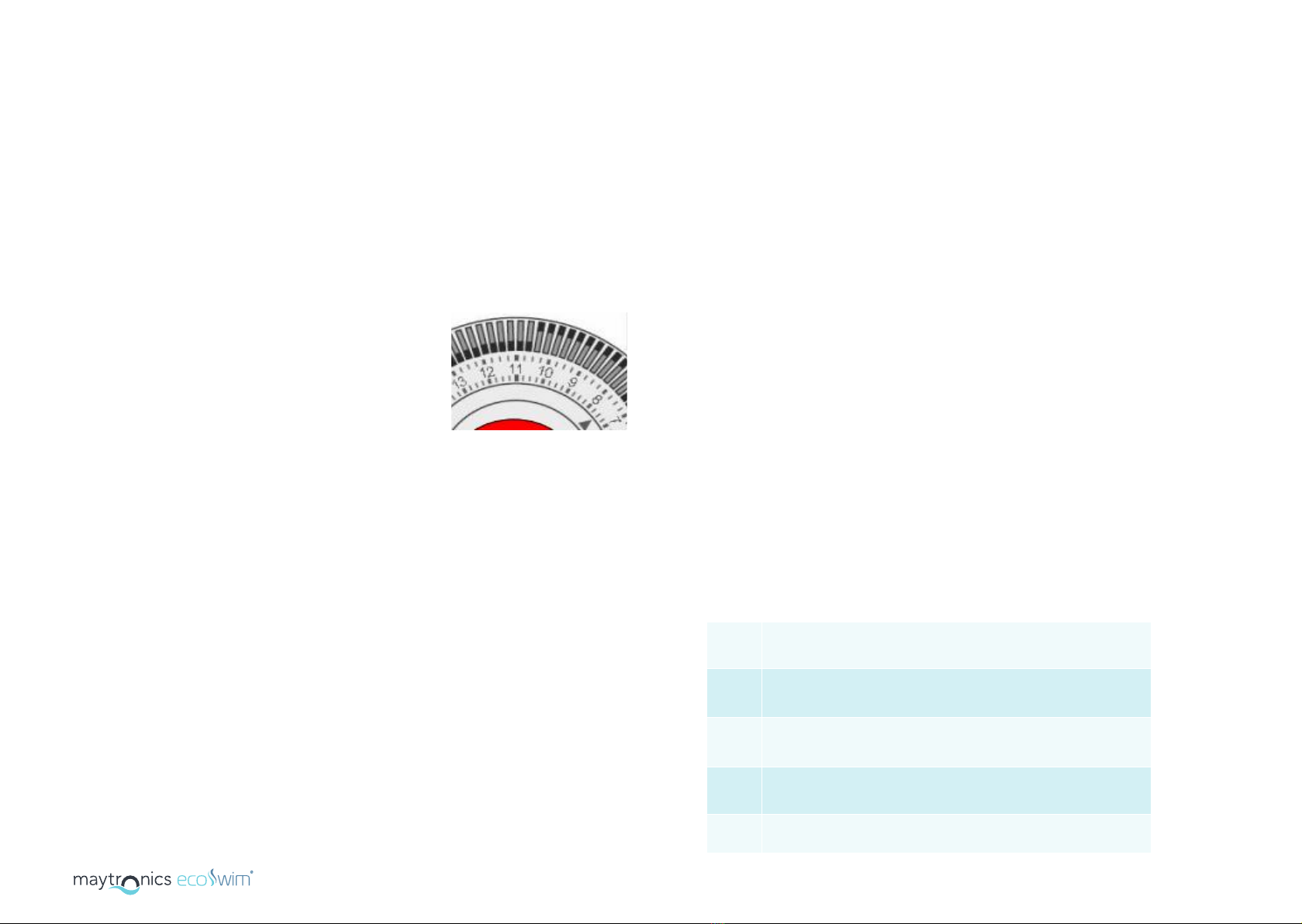
•To set current time, rotate minute hand clockwise until arrow head aligns with
correct time.
oNote: This will need to be reset whenever the power is disconnected from
the unit and for daylight saving time changes.
oNote: Only rotate clockwise to set. Rotating incorrectly will damage the time
clock.
•To set ON/OFF times, move required tappets to appropriate position. Inner position
for OFF and outer position for ON.
oNote: proper operation requires that the appropriate switch settings below
are enabled
•Each of the tappets on outer edge of the timer represents 15-minute intervals.
((NNOOTTEE)) IIff yyoouu rreeqquuiirree yyoouurr OOzzoonnee SSwwiimm ttoo bbee ccoonnnneecctteedd ttoo aann ooffff--ppeeaakk ttaarriiffff wwee rreeccoommmmeenndd tthhee
uussee ooff aann aapppprroopprriiaattee bbaatttteerryy bbaacckkuupp ttiimmee cclloocckk ffoorr tthhaatt ppuurrppoossee..
CChheecckkiinnggCChhlloorriinnaattiioonnoouuttppuutt
The chlorine cell output controller regulates the amount of chlorine production relevant to
the position it has been set to. By adjusting the cell output controller clockwise, you
increase chlorine production and by turning anti clockwise you reduce production. Do not
attempt to turn the controller beyond its stops as this could cause damage to your unit that
is not covered by warranty.
To ensure your Chlorinator is working correctly, follow the steps below
•Ensure the cell production is at maximum
•With the unit running take a sample of water from the skimmer box and conduct a
chlorine test, note the result
•Take a sample of water from directly in from of the return to the pool outlet and
conduct a chlorine test, note the result
•If the latter is higher in chlorine than the first test, your ozone Swim is efficiently
producing chlorine (if not please see troubleshooting)
CChheecckkiinnggOOzzoonneeoouuttppuutt
To ensure your Ozone is working follow the steps below
•Check that the green ozone light is on
• Set the master switch to the “on” position.
• Set the sanitation switch to “manual” position to turn the unit on.
• Once the salt/minerals have been added and dissolved turn the
cell production dial to the required position based on the season
and the size of the pool (set to max output to start with and
adjust down as required).
• Set the timer (see setting the timer) to run for the
recommended times (4-6 hours for winter / 8-10 hours for
summer), switch the system to auto and the unit will now be
controlled by the timer.
• To set current time, rotate minute hand clockwise until arrow
head aligns with correct time.
Note: This will need to be reset whenever the power is
disconnected from the unit and for daylight saving time changes.
Note: Only rotate clockwise to set. Rotating incorrectly will damage
the time clock.
• To set ON/OFF times, move required tappets to appropriate
position. Inner position for OFF and outer position for ON.
Note: proper operation requires that the appropriate switch
settings below are enabled.
• Each of the tappets on outer edge of the timer represents
15-minute intervals.
Note: If you require your Eco Swim to be connected to an o-peak
tari we recommend the use of an appropriate battery backup
time clock for that purpose.
Checking Chlorination Output
The chlorine cell output controller regulates the amount of chlorine production relevant
to the position it has been set to. By adjusting the cell output controller clockwise, you
increase chlorine production and by turning anti clockwise you reduce production. Do not
attempt to turn the controller beyond its stopping positions as this could cause damage to
your unit that is not covered by warranty.
To ensure your Chlorinator is working correctly, follow the steps below:
• Ensure the cell production is at maximum.
• With the unit running take a sample of water from the skimmer box and conduct a
chlorine test, note the result.
• Take a sample of water directly in front of the return to the pool outlet and conduct a
chlorine test, note the result.
• If the latter is higher in chlorine than the first test, your Eco Swim is eciently
producing chlorine (if not please see TROUBLESHOOTING).
Chlorine Cell Output Display Definitions
Your Eco Swim unit is fitted with a digital display. During operation of your Eco Swim unit
the display will illuminate relevant to the degree at which the chlorine output control
has been adjusted. You can increase or decrease chlorine output to suit your pool’s
requirements. As you increase the output (by turning the control knob clockwise), the
display will indicate % of full production capacity reading to the cell. You have full control
of chlorine production merely by adjusting the chlorine controller and illuminating the
number of lights to satisfy your chlorine demand.
The Eco Swim also has on board diagnostics to indicate any issues with the system (see
table below for definitions).
1-xx A value in the range of 0-99% indicates sanitation output.
OF Cell output control knob is turned o, the Eco Swim’s chlorination has
been manually switched o.
dg Automatic cleaning cycle beginning, the self-cleaning function is
beginning. This is only displayed for a short period.
Pb (Flashing) There is insucient water flow through the cell to produce.
if this persists, please refer to troubleshooting.
OL (Flashing) overload condition (see troubleshooting).

USER MANUAL16 17
MAINTENANCE
Maintenance
Regular water testing must be performed to ensure the water is within the
recommended ranges (see below):
Chlorine 1-3 ppm
pH 7.2 - 7.6
Total Alkalinity 80 - 120 ppm
Hardness 150 - 350 ppm
Cyanuric Acid (CA) 30 - 50 ppm
Phosphates 0 - 300 ppm
TDS 3500 - 4500 ppm
Water Chemistry (Balancing Information)
Electrode (Cell) Cleaning
Although you have a reverse cycle (automatic cell cleaning) system, it is
recommended from time to time that the cell be checked for any accumulation
of calcium or other deposits that may have built up. We recommend cleaning
the cell once or twice a year subject to your pool’s application and location.

USER MANUAL18 19
WARRANTY
Eco Swim systems have:
• 2 year parts replacement warranty (1 YEAR IN-FIELD) on the
conrol box.
• 5 year pro-rata warranty of chlorinator cell. (2 Year Full, year 3,
4, 5 Pro-rata).
Activate your Eco Swim warranty by registering at:
maytronics.com.au/support/registration
Warranty Information
5
Y
e
a
r
C
e
l
l
W
a
r
r
a
n
t
y
*
2
Y
e
a
r
F
u
l
l
W
a
r
r
a
n
t
y
5
Year
Warranty

USER MANUAL20 21
TROUBLESHOOTING
Troubleshooting
Fault Potential Causes Action Required
Cell output display flashing
“Pb” continuously (no water
flow)
• Pump turned o or
disconnected
• Valves closed
• Gas sensor wire at cell
disconnected
• Ensure pump is on
• Ensure correct valves are open
• Reconnect sensor wire at cell
Low salt indicator flashing • Salt level in pool has
dropped too low
• Pool water temperature is
low
• Cell has calcified
• Cell has failed
• Take sample of water to pool
shop and check salt level –
add salt as recommended
• Add salt and turn chlorinator
output down until the water
is warmer
• Ensure cell is clean
High Salt indicator flashing • Too much salt has been
added to the pool
• Take a sample to your local
pool shop to confirm salt
levels and remove and
replace water as required
No display • No mains power
• Unit is turned o
• Ensure there is mains power
available
• Check fuse condition and call
technician if blown
• Ensure manual mode and
sanitation are switched on
Low/No Chlorine • Insucient run times
• Incorrect cell production setting
• Low/high salt levels
• Loose connections at the cell
(red & black)
• Water chemistry
• Adjust run times to allow
more production
• Increase cell production
• Check/adjust salt levels to be
within required range
• Disconnect leads, then
reconnect leads firmly
• Take water sample to pool shop
Cell output flashing “OL” • Possible short circuit in cell
(debris)
• Extremely high salt levels
• Remove cell and check for
any debris and clean
• Check and adjust salt levels

maytronics.com.au
This manual suits for next models
2
Table of contents
Popular Swimming Pool Filter manuals by other brands

Hamma
Hamma RAPID 4 Operating instruction

Pahlen
Pahlen WIDE user manual

POLYGROUP LIMITED
POLYGROUP LIMITED RS600 Filter System with F600C Pump instructions

Arch
Arch hth easiflo 1 75876 Operator's manual

Davey
Davey Monarch EcoSalt BMSC Series Installation & operating instructions

Majestic
Majestic UNO Instructions for use

Pool Technologie
Pool Technologie JUSTSALT UNO Instructions for use

HEISSNER
HEISSNER F540-00 Instructions for use

SandPro
SandPro 4517 owner's manual

Jandy
Jandy AquaPure Ei Workbook

Jacuzzi
Jacuzzi Avalanche Owner's manual and installation guide

Zodiac
Zodiac TRi PRO Module Instructions for installation and use