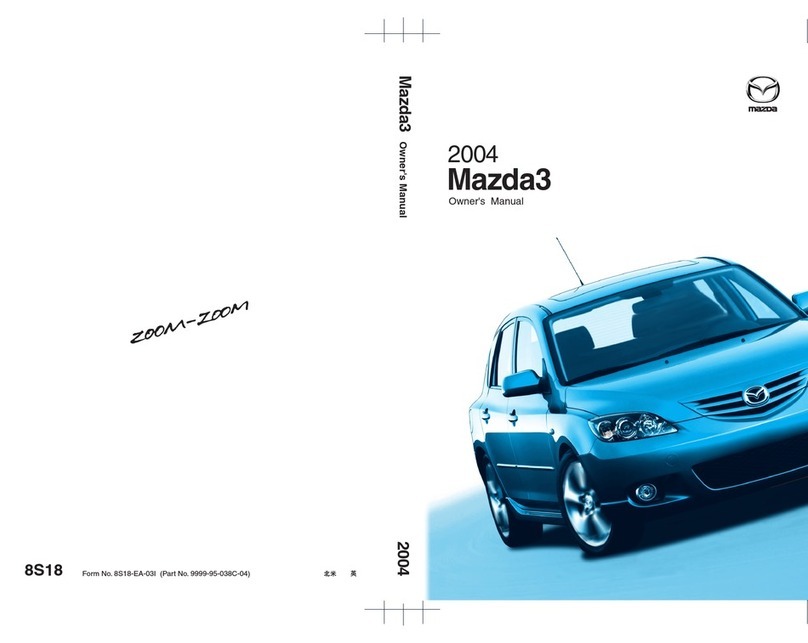
Mazda 626 1989 Instruction manual

1989
l¥ 3 a z d a
626
MX-6
Workshop
Manual
FOREWORD
This workshop manual is intended for use
b service technicians of authorized Mazda
dealers to help them service Mazda vehicles.
This manual can be also useful for Mazda own
ers in diagnosing certain problems and per
forming some repair and maintenance on
Mazda vehicles.
For proper repair and maintenance, it is im
portant to be thoroughl familiarized with this
manual. It is recommended that this manual al
wa s be kept in a hand place for quick and
eas reference.
All the contents of this manual, including pho
tographs, drawings, and specifications, are the
latest available at the time of printing. As modifi
cations affecting repair or maintenance occur,
relevant information supplementar to this
volume will be made available at Mazda deal
ers. This manual should be kept up-to-date.
Mazda Motor Corporation reserves the right
to alter the specifications and content^ of this
manual without obligation or advance notice.
All rights reserved. No part of this book ma
be reproduced or utilized in an form or b an
means, electronic or mechanical, including
photocop ing, recording, or b an informa
tion storage and retrieval s stem, without per
mission in writing.
CONTENTS
Title
General Information
Pre-Deliver Inspection and
Scheduled Maintenance Services
Engine
Lubrication S stem
Cooling S stem
Fuel and Emission
Control S stems Non-Turbo
Turbo
Engine Electrical S stem
Clutch
Transaxle Manual
Automatic
Front and Rear Axles
Steering S stem
Braking S stem
Wheels and Tires
Suspension
Bod
Bod Electrical S stem
Heater and Air Conditioning S stem
Technical Data
Special Tools
Wiring Diagram
Mazda Motor Corporation
HIROSHIMA JAPAN
© 1988 Mazda Motor Corporation
PRINT D IN JAPAN, JUNE '88 ®
1187-10-88F

PR -D LIV RY INSP CTION
AND
SCH DUL D MAINT NANC
S RVIC S
PRE-DELIVERY INSPECTION
.........
.
...............0— 2
PRE-DELIVERY INSPECTION TABLE.
.......
.
0— 2
SCHEDULED MAINTENANCE SERVICES .... 0— 3
MAINTENANCE TABLE (SCHEDULE 1)...... 0— 3
MAINTENANCE TABLE (SCHEDULE 2)...... Q~ 7
86U00X-001

0 PRE-DELSVERY SNSP CTION
PRE-DELIVERY INSPECTION
PRE-DELIVERY INSPECTION TABLE
EXTERIOR
INSP CT and ADJUST, if necessar , the following items to
the specifications:
□ Glass, exterior bright metal and paint for damage
□ Wheel lug nuts
88-118 N-m (9-12 m-kg, 65 -87 ft-lb)
□ Tire pressures (Refer to section 12)
□ All weatherstrips for damage or detachment
□ Operation of hood release and lock
□ Operation of fuel lid and trunk lid (Back door) opener
□ Door operation and alignment
□ Headlight aiming
INSTALL following parts:
□ Wheel caps or rings (if equipped)
□ Outside rear view mirror(s)
"UNDER HOOD—ENGINE OFF
INSP CT and ADJUST, if necessar , the following items to
the specifications:
□ Fuel, coolant and h draulic lines, fittings, connections and
components for leaks
□ Engine oi! level
□ Power steering fluid level (if equipped)
□ Brake and clutch master c linder fluid level (if equipped)
□ Windshield washer reservoir fluid level
□ Radiator coolant level and specific gravit
Protection °C (°F) Specific gravit at 20°C (68°F)
-16(3) 1.054
-26 (-15) 1.066
-40 (-40) 1.078
□ Tightness of water hose clamps (including heater hoses)
□ Tightness of batter terminals
□ Manual transaxle oil level
□ Drive belt tensions (Refer to section 1)
□ Accelerator cable and its linkage for free movement
□ Headlight cleaner fluid level (if equipped)
CLEAN spark plugs
INTERIOR
INSTALL the following parts:
□ Rubber stopper for inside rear view mirror
□ Fuse for accessories •
CHECK the operations of the following items:
□ Seat controls (sliding and reclining) and head rest
□ Door locks including childproof door locks (if equipped)
□ Seat belts and warning s stem
□ Ignition switch and steering lock
□ Inhibitor switch (ATX onl )
□ All lights including warning and indicator lights
□ Sound warning s stem
□ Headlight cleaner (if equipped)
□ Horn, wipers and washers (front and rear, if equipped)
□ Radio and antenna (if equipped)
□ Cigarette lighter and clock
□ Remote control outside rear view mirrors (if equipped)
□ Power windows (if equipped)
□ Heater, defroster and air conditioner at various mode selec
tion (if equipped)
□ Sunroof (if equipped)
ADJUST antenna trimmer on radio (if equipped)
CHECK the following items:
□ Presence of spare fuse
□ Upholster and interior finish
CHECK and ADJUST, if necessar , the following items:
□ Operation and fit of windows
□ Pedal height and free pla of brake and clutch pedal
Pedal height mm (in) free pla mm (in)
Clutch pedal 216.5-217 (8.52-8.54) 5—13 (0.2—0.51)
Brake pedal 222-227 (8.74-8.94) 4 -7 (0.16-0.28)
□ Parking brake
5 -7 noches/98 N (10 kg, 22lb)
UNDER HOOD—ENGINE RUNNING AT
OPERATING TEMPERATURE
_________
CHECK the following items:
□ Automatic transaxle fluid level
□ Initial ignition timing
Non-turbo 6° ± 1° BTDC
Turbo 9° ± 1° BTDC (with test connector grounded)
ON HOIST"
CHECK the following items:
□ Underside fuel, coolant and h draulic lines, fittings, connec
tions and components for leaks
□ Tires for cuts or bruises
□ Steering linkage, suspension, exhaust s stem and all under
side hardware for looseness or damage
REMOVE protective cover from brake discs
ROAD TEST"
CHECK the following items:
□ Brake operation
□ Clutch operation
□ Steering control
□ Operation of meters and gauge
□ Squeaks, rattles or unusual noise
□ Engine general performance (including turbo)
□ Emergenc locking retractors
□ Cruise control s stem (if equipped)
AFTER ROAD TEST
REMOVE seat and floor mat protective covers
CHECK for necessar owner information materials, tools and
spare tire in vehicle 86U00X-002
0 -2


96U00X-004
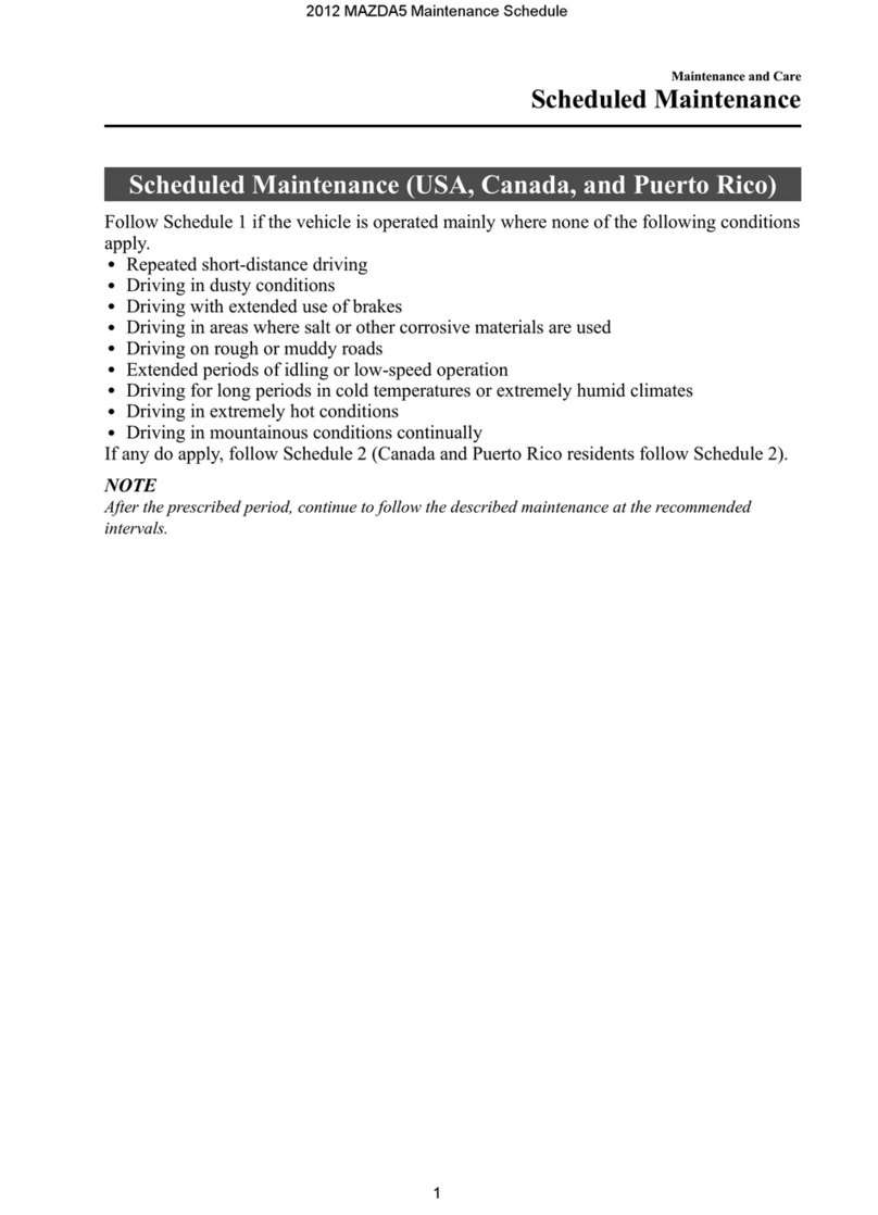
Follow Schedule 1 (Normal Driving Condition) if ou mainl operate our vehicle where none of the following conditions appl . (Except Canada)
Follow Schedule 2 (Unique Driving Condition) if one or more of the items below appl ;
• Repeated short distance driving.
• Driving in dust conditions.
• Driving a with extended use of brakes.
• Driving in areas using road salt or other corrosive materials.
• Driving on rough and/or mudd roads.
• Extended periods of idling and/or low-speed operation.
• Driving for a prolonged period in cold temperature and/or extremel humid climates.
SCH DUL 1 (NORMAL DRIVING CONDITION)
Chart symbols:
I : Inspect, and if necessar correct, clean or replace
R: Replace or change
T : Tighten
L: Lubricate
Remarks;
After 60 months or 60,000 miles (96,000km), continue to follow the described maintenance items and intervals periodicall .
As for * marked items in this-jjiaintenance chart, please pa attention to the following points.
*1 Replacement of the timing belt is required at ever 60,000 miles (96,000km). Failure to replace the timing belt ma result in damage to the engine.
*2 This maintenance operation is recommended b Mazda. However, this maintenance is not necessar for emission warrant coverage or manufacturer recall liabilit .
m
o
m
H
>
DO
r~
m
O)
o
x
m
o
c
r~
m
(/>
0
1
m
o
c
r~
m
o
m
O
m
c/>
m
J3
<
o
m
(A
to
0
1
m
D
c
r~
m
D
S
>
m
z
>
z
o
m
to
m
DO
<
O
m
to

96U00X-001
0
1Interval
Procedure & item
Number of months or km (miles) whichever comes first
Service data and inspection point Page
Months 7.5 15 22.5 30 37.5 45 52.5 60
Miles 7,500 15,000 22,500 30,000 37,500 45,000 52,500 60,000
Kilometers 12,000 24,000 36,000 48,000 60,000 72,000 84,000 96,000
Steering operations and linkage II• Free pla : 0—30 mm (0— 1.18 in)
• Operation and looseness
• Fluid leakage or oozing
10—10
10-13
Air cleaner element RR—4A—32
4B -37
Spark plugs
RR
• Plug gap: 1
(0.039—0.0-
• Recommenc
NGK
Nippon
Denso
0—1.1 mm
*3 in)
ted spark plugs
ZFR5A-11
ZFR6A-11
ZFR7A-11
QJ16CR11
QJ20CR11
QJ22CR11
5 -2 7
Cooling s stem '« I III• Hoses for cracks or wear
• Coolant level 3—4
Engine coolant R R—3—4
Drive belts I I• Cracks or damage
• Tension 1—6
Fuel filter R—4A—57
4B -69
Fuel lines | *2 I• Fittings, connections and compo
nents for leaks 4 A—41
4B -52
Brake lines, hoses and connections I I • Proper attachment and connections 11 -7
Engine timing belt*1 Replace ever 60,000 miles (96,000 km) —1 -1 0
Engine oil Non-turbo RR R R R RRR• Oil pan capacit : 3.9 liters
(4.1 US qt, 3.4 Imp qt) 2—4
Turbo Replace ever 5,000 miles (8,000 km) or 5 months
Oil filter Non-turbo RR R R R R R R • Oil filter capacit : 0.3 liters
(0.32 US qt, 0.26 Imp qt) 2 -5
Turbo Replace ever 5,000 miles (8,000 km) or 5 months
Drum brakes I I• Min. lining thickness:
1.0 mm (0.04 in)
® Max. drum inner dia.:
230.1 mm (9.06 in)
11—47
Disc brakes II• Min. pad thickness:
Front 2.0 mm (0.08 in)
Rear 1.0 mm (0.04 in)
• Min. disc thickness:
Front 22.0 mm (0.87 in)
Rear 8.0 mm (0.31 in)
• Disc run-out: 0.1 mm (0.004 in)
11-33,41
11-33,41
11-33,41
m
o
m
H
>
CO
I-
m
w
0
1
m
o
c
i-
m
to
o
X
m
o
c
r~
m
o
H
m
o
m
TO
m
u
<
o
m
(/>

96U00X-002
Interval
Procedure & item
Number of months or km (miles) whichever comes first
Service data and inspection point Page
Months 7.5 15 22.5 30 37.5 45 52.5 60
Miles 7,500 15,000 22,500 30,000 37,500 45,000 52,500 60,000
Kilometers 12,000 24,000 36,000 48,000 60,000 72,000 84,000 96,000
Front suspension ball joints I I • Damage, looseness and grease
leakage 13—14
Drive shaft dust boots I I• For cracks, damage, leakage of
grease or looseness of band 9 -3 2
9—35
Rear suspension ball joints
(4-wheel steering vehicle onl ) II• Damage, looseness and grease
leakage 13—31
4-wheel steering s stem operation and
linkage II• Operation and looseness
• Fluid leakage or oozing
o o
^ o
Steering angle of rear wheels (4-wheel
steering vehicle onl ) II• Steering wheel angle:
Inner 5° 00’ ± 45’
Outer 5° 00’ ± 45’
13-47
Solenoid valve oil filter for 4-wheel
steering s stem RR— 10-38
Exhaust s stem heat shield II• Clearance to bod , and exhaust
s stem 4A—74
Bolts and nuts on chassis and bod TT— —
Air conditioner s stem
(if equipped) Refrigerant Inspect the refrigerant amount annuall 950-1,050 g (33:5—37.1 oz) 16—39
Compressor Inspect the operation annuall —16-42
m
z
>
z
o
m
H
>
W
r~
m
w
0
1
m
o
m
m
o
X
m
o
c
r~
m
o
£
>
z
H
m
z
>
z
o
m
co
m
30
<
O
m
co

86UOQX-006
9 SCH DUL 2 (UNIQU DRIVING CONDITION)
cn Chart symbols:
I : Inspect, and if necessar correct, clean or replace Z (/)
R: Replace or change O
T : Tighten Z -E
L: Lubricate > HJ
O
Remarks: ni
After 60 months or 60,000 miles (96,000km), continue to follow the described maintenance items and intervals periodicall . _j jjg
As for * marked items in this maintenance chart please pa attention to the following points. > q
*1 Replacement of the timing belt is required at ever 60,000 miles (96,000km). Failure to replace the timing belt ma result in damage to the engine. 00
m
*2 This maintenance operation is recommended b Mazda. However, this maintenance is not necessar for emission warrant coverage or manufacturer recall liabilit .
*3 This maintenance operation is required for Canada and all states except California. However we do recommend that this operation be performed on California vehi- _ ^
cles as well. W 2
O H
m m
c >
s 3
£ m
C/5
m
33
<
o
m
O)

96U00X-Q03
Interval
Procedure & item
Number of months or km (miles) whichever comes first
Service data and inspection point Page
Months 5 10 15 20 25 30 35 40 45 50 55 60
Miles
(x1,000) 5 10 15 20 25 30 35 40 45 50 55 60
Kilometers
(x1,000) 8 16 24 32 40 48 56 64 72 80 88 96
Steering operations and linkage I'• Free pla : 0—30 mm (0—1.18 in)
• Operation and looseness
• Fluid leakage or oozing
10—10
10—13
Air cleaner element j *3 Rj *3 R—4A—32
4B—37
Spark plug
RR
• Plug gap: 1
(0.039—0.0-
• Recommenc
NGK
Nippon
Denso
0—1.1 mm
43 in)
led spark plugs
ZFR5A-11
ZFR6A-11
ZFR7A-11
QJ16CR11
QJ20CR11
QJ22CR11
5—27
Cooling s stem I'I I • Hoses for cracks or wear ■
• Coolant level 3—4
Engine coolant R R — 3 -4
Drive belts I I• Cracks or damage
• Tension 1—6
Fuel filter R—4A—57
4B—69
Fuel lines j *2 I• Fitting, connections and compo
nents for leaks 4 A—41
4B—52
Brake lines, hoses and connections II• Proper attachment and connections 11—7
Engine timing belt*1 Replace ever 60,000 miles (96,000km) —1 -1 0
Engine oil Non-turbo R R R R R R R R R R R R • Oil pan capacit :
3.9 liters (4.1 US qt, 3.4 Imp qt) 2—4
Turbo Replace ever 3,000 miles (5,000km) or 3 months
Oil filter Non-turbo RRRRRRR R | R R R j R • Oil filter capacit :
0.3 liters (0.32 US qt, 0.26 Imp qt) 2—5
Turbo Replace ever 3,000 miles (5,000km) or 3 months
Drum brakes II• Min. lining thickness:
1.0 mm (0.04 in)
• Max. drum inner dia.:
230.1 mm (9.06 in)
11—47
Disc brakes
'III
• Min. pad thickness:
Front 2.0 (0.08 in)
Rear 1.0 mm (0.04 in)
• Min. disc thickness:
Front 22.0 mm (0.87 in)
Rear 8.0 mm (0.31 in)
• Disc run-out: 0.1 mm (0.004 in)
11-33,41
11-33,41
11-33,41
m
z
>
z
o
m
—i
>
co
r~
m
Tn
o
x
m
o
c
i—
m
NJ
w
0
1
m
o
c
i”
m
o
>
z
H
m
z
>
z
o
m
</>
m
J3
<
o
m
co
O

96U00X-004
0
1
CO
I
■!
.
Interval
Procedure & item
Number of months or km (miles) whichever comes first
Service data and inspection point Page
Months 5 10 15 20 25 30 35 40 45 50 55 60
Miles
(x1,000) 5 10 15 20 25 30 35 40 45 50 55 60
Kilometers
(x1,000) 8 16 24 32 40 48
I
56 64 72 80 88 96
Front suspension ball joints I • Damage, looseness and grease
leakage 13—14
Drive shaft dust boots I I • For cracks, damage, leakage of
grease or looseness of band
C\l LO
CO CO
I I
CD CT)
Rear suspension ball joints
(4-wheel steering vehicle onl ) I I • Damage, looseness and grease
leakage 13—31
4-wheel steering s stem operation and
linkage I I • Operation and looseness
• Fluid leakage or oozing 10—10
10—14
Steering angle of rear wheels
(4-wheel steering vehicle onl ) I I • Steering wheel angle:
Inner 5° 00’ ± 45’
Outer 5° 00' ± 45’
13—47
Solenoid valve oil filter for 4-wheel
steering s stem R R —10-38
Exhaust s stem heat shield ' II• Clearance to bod , and exhaust
s stem 4A—74
Bolts and nuts on chassis and bod T T T T — —
Air conditioner s stem
(if equipped) Refrigerant Inspect the refrigerant amount annuall 950—1,050 g (33.5—37.1 oz) 16—39
Compressor Inspect the operation annuall —16—42
m
z
>
z
o
m
—i
>
cn
i”
m
w
o
x
m
o
c
r~
m
to
CO
o
X
m
o
m
O
m
2
>
Z
o
m
co
m
33
<
o
m
co

G
G N RAL INFORMATION H
IMPORTANT INFORMATION
........
,
...........
.
G— 2
FUNDAMENTAL PROCEDURES
.................
.
G
...
2
JACK AND SAFETY STAND (RIGID RACK)
POSITIONS
.
.............
.
..............
.
.........................G— 6
VEHICLE LIFT (2-SUPPORT TYPE}
POSITIONS........................................................G— 6
TOWING
.
...................
.
..........................................G— 7
CHASSIS NUMBER LOCATION
.
.....................G— 8
ENGINE MODEL AND NUMBER
LOCATION
.
..........................................
.
G— 8
UNITS....................................................
.
...............
G— 8
ABBREVIATIONS...
............................
.
.............
.
G - 8
CAUTION
...............
.
..............................................G— 9
WARNING
................
.
.......................
.
.........
.
.......
G— 9
96U0GX-001
V

G IMPORTANT INFORMATION/FUNDAM NTAL PROC DUR S
IMPORTANT INFORMATION
BASIC ASSUMPTIONS
This workshop manual assumes that ou have and know how to properl use certain special tools which
are necessar for the safe and efficient performance of service operations on Mazda vehicles. The manual
also assumes that ou are familiar generall with automobile s stems and basic service and repair proce
dures. You should not attempt to use this manual unless these assumptions are correct and ou understand
the consequences described below.
SAFETY RISK
This manual contains certain notes, warnings, etc., which ou should carefull read and follow in or
der to eliminate the risk of personal injur to ourself or others and the risk of improper service which ma
damage the vehicle or render it unsafe. The fact that there are no such notes, etc., with respect to an specif
ic service method does not mean that there is no possibilit that personal safet or vehicle safet will be
jeopardized b the use of incorrect methods or tools.
POSSIBLE LOSS OF WARRANTY
The manufacturer’s warrant on Mazda vehicles and engines can be voided if improper service or repairs
are performed b persons other than an authorized Mazda dealer.
FUNDAMENTAL PROCEDURES
As ou read through the procedure, ou will come across
NOTES, CAUTIONS, and WARNINGS. Each one is there for
a specific purpose. NOTES give ou added information that
will help ou to complete a particular procedure. CAUTIONS
are given to prevent ou from making an error that could dam
age the vehicle. WARNINGS remind ou to be especiall
careful in those areas where carelessness can cause persona!
injur . The following list contains some general WARNINGS
that ou should follow when ou work on a vehicle.
PROTECTION OF THE VEHICLE
Alwa s be sure to cover fenders, seats, and floor areas be
fore starting work.
A WORD ABOUT SAFETY
The following precautions must be followed when jacking up
the vehicle.
1. Block wheels.
2. Use onl specified jacking positions.
3. Support vehicle with safet stands (rigid racks).
Start the engine onl after making certain the engine compart
ment is clear of tools and people.
G—2 47U0GX-Q03

FUNDAM NTAL PROC DUR S G
47U0GX-004
47U0GX-005
PREPARATION OF TOOLS AND MEASURING
EQUIPMENT
Be sure that all necessar tools and measuring equipment are
available before starting an work activit .
SPECIAL TOOLS
Use special tools when the are required.
REMOVAL OF PARTS
While correcting a problem, tr also to determine its cause.
Begin work onl after first learning which parts and subassem
blies must be removed and disassembled for replacement or
repair.
47U0GX-006 DISASSEMBLY
If the disassembl procedure is complex, requiring man parts
to be disassembled, all parts should be disassembled in a wa
that will not affect their performance or external appearance,
and be identified so that reassembl can be performed easil
and efficientl .
DISASSEMBLY
1. Inspection of parts
Each part when removed should be carefull inspected for
malfunctioning, deformation, damage, and other problems.
G—3

G FUNDAM NTAL PROC DUR S
2. Arrangement of parts
Al! disassembled parts should be carefull arranged for reas
sembl .
Be sure to separate or otherwise identif the parts to be
replaced from those that will be reused.
47U0GX-009 3. Cleaning parts for reuse
All parts to be reused should be carefull and thoroughl
cleaned in the appropriate method.
REASSEMBLY
Standard values, such as torques and certain adjustments,
must be strictl observed in the reassembl of al! parts.
If removed, these parts should be replaced with new ones:
1. Oil seals
2. Gasket
3. O-rings
4. Lock washers
5. Cotter pins (split pins)
6. N lon nuts
Depending on where the are;
1. Sealant should be applied to gaskets
2. Oil should be applied to the moving components of parts
3. Specified oi! or grease should be applied at the prescribed
locations (oil seals, etc.) before assembl .
ADJUSTMENTS
Use suitable gauges and/or testers when making various ad
justments.
47U0GX-010
47U0GX-011
47U0GX-012
G -4 67U0GX-002

FUNDAM NTAL PROC DUR S G
ELECTRICAL SYSTEM
Be sure to disconnect the batter cable from the negative (-)
terminal of the batter .
Never pull on the wiring when disconnecting connectors.
When locking connectors, make sure to listen for a click that
will let ou know the are securel locked.
Handle sensors and rela s carefull . Be careful not to drop
them or strike them against other parts.
RUBBER PARTS AND TUBING
Alwa s prevent gasoline or oil from getting on rubber parts
or tubing.
47U0GX-014
47U0GX-015
G -5

G JACK AND SAFETY STAND (RIGID RACK) POSITIONS, VEHICLE LIFT (2-SUPPORT TYPE) POSITIONS
JACK AND SAFETY STAND (RIGID RACK) POSITIONS
FRONT END
Jack position:
At the center of the crossmember Safet stand positions:
On both sides of the bod frame
REAR END
Jack position:
At the center of the rear crossmember Safet stand positions:
On both sides of the bod frame
VEHICLE LIFT (2-SUPPORT TYPE) POSITIONS
FRONT END
Frame
Side sills (front)
REAR END
Frame
Side sills (rear)
G -6

TOWING G
TOWING
Proper lifting or towing procedures are necessar to prevent
damage to the vehicle during an towing operation. State and
local laws applicable to vehicles in tow must be followed.
With eigher automatic or manual transaxle, release the park
ing brake, place the selector lever (or shift lever) in neutral and
set the ignition ke in the “ACC” position. As a general rule,
towed vehicles should be pulled with the driving wheels off
the ground.
86U0GX-006 If excessive damage or other conditions prevent towing the
vehicle with the driving wheels off the ground, use wheel
dollies.
Caution
Do not tow the vehicle backward with driving wheels
on the ground.
This ma damage the transaxle internal parts.
Do not start or run the engine while vehicle is being
towed.
(Onl for 4WS vehicle)
When towing the vehicle with the front wheels, raised,
be sure the rear wheels are in the straight-ahead po
sition.
Tie-down hook —- Front Caution
Do not use the hook loops under the front and rear
of vehicle for towing purposes. These hook loops are
designed ONLY for transport tie-down. If tie-down
hook loops are used for towing, front/rear skirt and
bumper will be damaged.
86U0GX-007
G—7

G CHASSIS NUMB R LOCATION/ABBR VIATIONS/UNITS
CHASSIS NUMBER LOCATION
ENGINE MODEL AND
NUMBER LOCATION
UNITS
N-m (m-kg or cm-kg,
ft-lb or in-lb)
...................
Torque
rpm..................................Revolutions per minute
A
......................................
Ampere(s)
V
......................................
Volt(s)
fi
......................................
Ohm(s) (resistance)
kPa (kg/cm2 psi)
...........
Pressure
(usuall positive)
mmHg (in Hg)
..............
Pressure
(usuall negative)
W
.....................................
Watt
mm (in)
...........................Length
liters (US qt, Imp qt)
....
Volume
oz
....................................
ounce
96U0GX-002
ABBR VIATIONS
A /C
......................
Air conditioner
ACC
.....................
Accessories
ABDC
..................
After bottom dead center
ADD
.....................
Additional fan
ATDC
...................
After top dead center
ATX
......................
Automatic transaxle
ATF
......................
Automatic transaxle fluid
ABS
.....................
Anti-lock brake s stem
BBDC
..................
Before bottom dead center
BTDC
...................
Before top dead center
EX.........................Exhaust .
EC-AT
..................Electronicall controlled
automatic transaxle
ESPS
....................
Engine speed sensing power
steering
ECPS
...................
Electronicall -controlled pow
er steering
HLA
.....................
H draulic Lash Adjuster
IG
..........................Ignition
IN..........................Intake
1C..........................Integrated circuit
INT........................Intermittent
LH.........................Left hand
MTX
.....................
Manual transaxle
M
..........................
Motor
OFF
.....................
Switch off
ON........................Switch on
PCV
.....................
Positive crankcase ventilation
P/S........................Power steering
P/W
......................
Power window
RH........................Right hand
ST.........................Start
SW........................Switch
SST.......................Service special tools
4WS
.....................
4-wheel steering
2WS
.....................
2-wheel steering
67U0GX-005
96U0GX-003

CAUTION, WARNING G
CAUTION
INSTALLATION OF A MOBILE TWO-WAY RADIO SYSTEM
If a mobile two-wa radio s stem is installed improperl , or if a wrong t pe is used, the Fuel Injection s stem
and other s stems ma be affected.
When car is equipped with a mobile two-wa radio s stem, observe the following precautions.
1. Install the antenna at the farthest point from the control unit.
2. Keep the antenna feeder awa from the control unit harness as far as possible.
(at least 30cm (11.8 in))
3. Insure that the antenna and feeder are properl adjusted.
4. Do not install a powerful mobile two-wa radio s stem.
86UQGX-002
Feeder control unit
Wire Harness
. 96U0GX-004
WARNING ■'
LUBRICANTS AND GREASES
Avoid all prolonged and repeated contact with mineral oils, especiall used oils. Used oils contaminated
during service (e.g. engine sump oils) are more irritating and more likel to cause serious effects including
skin cancer in the event of gross and prolonged skin contact.
Wash skin thoroughl after work involving oil. Proper hand cleaners ma be of value provided the can be
removed from the skin with water. Do not use petrol, paraffin or other solvents to remove oil from the skin.
Lubricants and greases ma be slightl irritating to the e es.
Repeated or prolonged skin contact should be avoided b wearing protective clothing if necessar . Particu
lar care should be taken with used oils and greases containing lead. Do not allow work clothing to be con
taminated with oil. Dr clean or launder such clothing at regular intervals.
G—9

INSP CTION AND R PAIR I B
in
6. Measure the camshaft end pla . If It exceeds the
maximum, replace the camshaft and/or the c lin
der head.
nd play:
0.08—0.10 mm (0.003—0.004 in)
Maximum: 0.20 mm (0.008 in)
Hydraulic Lash Adjuster (HLA)
1. Check the HLA face for wear or damage.
2. Hold the HLA between our fingers and press it.
if the HLA moves, replace it.
Caution
Do not disassemble the HLA.
Cylinder Block
Note
If the cylinder block is replaced, install the
dowel pin to the cylinder block.
1. Check the c linder block. Repair or replace if
necessar .
(1) Leakage damage
(2) Cracks
(3) Scoring of wall
2. Measure the distortion of the top surface of the c l
inder block in the six directions as shown in the
figure.
Distortion: 0.15 mm (0.006 in) max.
3. If the distortion exceeds the maximum, repair b
grinding, or replace the c linder block.
Grinding limit: 0.20 mm (0.008 in) max.
1B—41

1B INSP CTION AND R PAIR
79G01C-070
I I'1.:'
I f v ?/'.' V ■
I ■■
79G01C-071
4. Measure the c linder bore in directions X and Y
at three levels in each c linder as shown.
Cylinder bore mm (in)
Size Bore
Standard 86.000—86.019 (3.3858-3.3866)
0.25 (0.010) oversize 86.250—86.269 (3.3957—3.3964)
0.50 (0.020) oversize 86.500—86.519 (3.4055-3.4062)
(1) If the difference between the measurement A
and C exceeds the maximum taper, rebore the
c linder to oversize.
Taper: 0.019 mm (0.0007 in) max.
(2) If the difference between the measurement X
and Y exceeds the maximum out-of-round, re
bore the c linder to oversize.
Out*of-round: 0.019 mm (0.0007 in) max.
Caution
The boring size should be based on the size
of an oversize piston and be the same for all
cylinders.
5. If the upper part of the c linder wall shows uneven
wear, remove the ridge with a ridge reamer.
86U01X-102
This manual suits for next models
1
Table of contents
Other Mazda Automobile manuals

Mazda
Mazda CX-5 Guide

Mazda
Mazda 626 1981 Instruction manual

Mazda
Mazda mx-5 2016 Install guide

Mazda
Mazda 3 i User manual

Mazda
Mazda 2013 MX-5 Miata Guide

Mazda
Mazda 6 2003 Reference manual

Mazda
Mazda 8T12-EA-03K User manual

Mazda
Mazda MX-5 Miata User manual

Mazda
Mazda 2005 MPV User manual

Mazda
Mazda mazda3 2015 User manual

Mazda
Mazda 6 2017 User manual

Mazda
Mazda 6 MPS 2005 Installation guide

Mazda
Mazda 2 Operating and installation instructions

Mazda
Mazda PROTEGE 5 User manual

Mazda
Mazda MX-3 1995 Instruction manual

Mazda
Mazda 2011 CX-9 Guide

Mazda
Mazda 1978 GLC Instructions for use

Mazda
Mazda CX-8 User manual

Mazda
Mazda 2008 Mazda5 User manual

Mazda
Mazda 5 2014 Guide