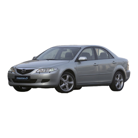
Mazda 626 MX-6 1989 Quick start guide

h h O £ ( \ b 0 ) O Z l

1989
Mazda
626
MX-6
HOW TO USE THIS WIRING DIAGRAM
SYMBOLS IN THIS WIRING DIAGRAM
HOW TO READ ELECTRIC PARTS 50-3
Wiring Diagram
OREWORD
This wiring diagram incorporates the wiring schem atic
for the basic vehicle and its available optional e quip
ment. Actual vehicle w iring m ay vary slightly depending
upon optional equipm ent and/or local specification. All
information contained in this booklet is based on the
latest information available at the tim e of printing. M azda
Motor C orporation reserves the right to make changes
without previous notice.
PARTS LOCATION
HARNESS DIAGRAM 50-122
Mazda Motor Corporation
HIROSHIMA, JAPAN
© 1988 Mazda Motor Corporation
PRINTED IN JAPAN Jun. 88 ®
5120-10-88

SYSTEM NAME
SYSTEM PAGE
ANTI-LOCK BRAKE SYSTEM
........................
5 0 - 96
AUDIO SYSTEM
.................................................
50-112
AUDIO SYSTEM
.................................................
50-114
AUTO ADJUSTING SUSPENSION
...............
5 0 - 70
AUTOMATIC SHOULDER BELT CONTROL ...5 0 - 88
BACK-UP LIGHTS
.............................................
50-52
CHARGING SYSTEM (EC-AT)
........................
5 0 - 18
CHARGING SYSTEM (M/T)
............................
50-16
CIGARETTE LIGHTER
.....................................
5 0 - 62
COOLING AN SYSTEM
(EXCEPT NON TURBO M/T)
........................
5 0 - 34
COOLING AN SYSTEM
(NON TURBO M/T)
.........................................
5 0- 32
COURTESY LIGHTS
.........................................
50-66
CRUISE CONTROL SYSTEM
(NON TURBO) .................................................. 50-76
DIGITAL CLOCK
..................................................
50-62
DIGITAL ELECTRONIC DISPLAY
....................
50-120
EC-AT CONTROL SYSTEM
............................
5 0 - 92
ELECTRICAL WIRING SCHEMATIC
...........
50-15
ENGINE CONTROL SYSTEM
(NON TURBO)
.................................................
50-20
ENGINE CONTROL SYSTEM (TURBO)
.......
5 0- 26
RONT OG LIGHTS
.........................................
50-44
RONT PARKING LIGHTS
............................
5 0 - 44
RONT SIDE MARKER LIGHTS
....................
5 0 - 44
^-^fR O N T WIPER & WASHER
............................
50-40
UEL INJECTION SYSTEM
(NON TURBO)
.................................................
50-20
UEL INJECTION SYSTEM (TURBO)
...........
5 0 - 26
HARNESS DIAGRAM
.........................................
50-124
HEADLIGHT CLEANER
.....................................
50-40
HEADLIGHTS
......................................................
5 0 - 44
HEATER & A/C (LOGICAL)
............................
50-59
HEATER & A/C (MECHANICAL)
....................
5 0 - 56
HIGH MOUNTED STOP LIG H T
........................
5 0 - 52
SYSTEM PAGE
HORN
..................................................................
5 0 - 52
HOW TO READ ELECTRIC PARTS
................
5 0 - 8
HOWTO USE THIS WIRING DIAGRAM
.......
5 0 - 3
IGNITION SYSTEM (NON TURBO)
................
5 0 - 20
IGNITION SYSTEM (TURBO)
........................
5 0 - 26
ILLUMINATION LIGHTS CONTROL
............
5 0 - 48
INTER CONNECTING O JOINT BOX
.......
50-118
INTERIOR & SPOT LIGHTS
............................
5 0 - 66
JOINT BOX
..........................................................
50-119
JOINT CONNECTOR & GROUND CIRCUIT ...50- 14
LICENSE LIGHTS
..............................................
50-44
LUGGAGE COMPARTMENT LIGHT ............ 50-62
METERS & WARNING LIGHTS
........................
5 0 - 36
PARTS INDEX
......................................................
5 0 - 10
PARTS LOCATION .............................................. 50-122
POWER ANTENNA
..............................................
50-110
POWER DOOR LOCK
.....................................
50-104
POWER STEERING CONTROL
........................
5 0 - 88
POWER SYSTEM
..............................................
50-12
POWER WINDOW (2 DOOR)
........................
5 0 - 82
POWER WINDOW (4 & 5 DOOR)
....................
5 0 - 78
REAR HATCH
.......................................................
50-104
REAR SIDE MARKER LIGHTS
........................
5 0 - 44
REAR WINDOW DE ROSTER
........................
5 0 - 62
REAR WIPER & WASHER
.................................
5 0 - 40
REMOTE CONTROL MIRROR
........................
5 0 - 68
SLIDING SUNROO
.........................................
50-108
SOUND WARNING SYSTEM
........................
5 0 - 84
STARTING SYSTEM (M/T) 50-16
STARTING SYSTEM (EC-AT)
........................
50-18
STOP LIGHTS
......................................................
5 0 - 52
SYMBOLS IN THIS WIRING DIAGRAM
.......
5 0 - 7
TAIL LIGHTS
......................................................
5 0 - 44
THE T-DETERRENT CONTROL SYSTEM
.......
5 0 - 84
TURN & HAZARD LASHER LIGHTS
...........
5 0 - 52
4WS CONTROL SYSTEM
.................................
50-100

The Way to View a Wiring Diagram
This Wiring Diagram is made up of circuit diagrams, connector diagrams, location diagrams, and
harness diagrams.
The circuit diagrams are divided according to each system, and by using them, the wiring of each
system's circuit can be understood.
Connector diagrams and location diagrams are divided according to vehicle harness, and the
location diagrams are designed so that the connector locations and the circuit’s course in the
vehicle harnesses can be understood.
rom the connector diagrams the connector shape and the arrangement of the pins used in the
circuit diagrams can be understood.
In the circuit diagrams and the location diagrams, the different kinds of harnesses are colored
differently, which makes easy distinguishing.
The harness diagrams on the last page can be understood to indicate the connector shape for
each harness, the wiring color, and each part and each turning point in the vehicle.
Circuit Diagram Connector Diagram
Designed so that operation of electrical parts and the Lists the connectors that are used in the circuit on the
layout of the wiring may be understood. left page
As a rule, it shows the connectors on the harness side.

HOW TO USE THIS WIRING DIAGRAM 50
Location Diagram
This page illustrates the actual location of each connector and the routing diagram of the harness.
Harness Diagram
Indicate the connectors used in the circuit diagrams, arranging them according to each different kind of harness.
50-3

50 HOW TO USE THIS WIRING DIAGRAM
Overview of Power Source Diagrams and Ground Circuit Diagrams
The electrical power sources on the circuit are shown by designated code numbers. Therefore, by extending to the left
the folding power source diagram, the power sources and fuse that are used be seen and understood at one glance.
Ignition Switch
Here are listed together the fuses that have
been designated for use in the vehicle.
50-4

The ground locations are shown on the diagram.
Made so the way in which each load is grounded
may be understood.

HOW TO USE THIS WIRING DIAGRAM 50
Some Points to Remember When Viewing a Wiring Diagram Some Poin,s t0 Remember When Viewing a Connector Diagram
WIRING COLOR CODE
Two-color wires are indicated by a Two-letter symbol. The first letter indicates
the base color of the wire and the second indicates the color of the stripe.
or example:
W/R is a white wire with a red strip
-------------
-
BR/Y is a brown wire with a yellow strip
CODE]- COLOR IcODE COLOR f W/R[ ]
B Black LG Light green I f y
BR Brown 0 Orange y \ I Basic color \
G Green R Red I I Stripe color
L Blue Y Yellow \
_ LB Light blue W ! White \
P Pink V * Violet S
~ GY Gray
_____________
r -11 >
STARTER CUT
RELAY ( ) Connector numbers are written in sequence according to each harness, and the
letter at the head of each code number indicates the kind of harness.
or example:
‘‘ -11" stands for the 11th connector in the ront Harness.
Direction of current is
shown by the arrow
Current
W/R[ ]
■ STARTING SYSTEM CONNECTOR AND NO,
Alternator
warning light
(Page 40)
emale male
The connector numbers are
dicided according to each kind of
harness.
or example:
Legend in the parenthesis
( ) indicates the reference
Page.
ront Harness
Instrument panel Harness
Rear Harness
Abbreviation
The Way to View a Electrical Wiring Schematic
The electrical wiring schematic explains the outline of all the electrical parts in the vehicle.
Also, it clarifies power line and the way to use each fuses.
Switch
NO switch NC switch
—|— —|— ■ ELECTRICAL WIRING SCHEMATIC
The NC (Normally Closed) type
relay and switch are shown by
• the NO (Normally Open) are
shown by “O".
These are shown without opera
tion in this book. ■ STOP LIGHTS
60A
BATTERY
© © I 30A ■
..........
■ CARGO ROOM LIGHT
■ COURTESY LIGHTS
■ INTERIOR & SPOT LIGHTS
20A fuse blow out — check the stop lights circuit.
50-5

50 HOW TO USE THIS WIRING DIAGRAM
Some Points to Remember When Viewing a Location Diagram
Connectors in circuit diagram are all described in location diagram, and connector
numbers are shown by leader line.
Each frame has the alphabets and numerical numbers to search the connector easily.
or example:
“ -11" connector is across "E" on horizontal line and “7" on vertical line
Connector Color:
Color is shown unless connector is white.
50-6

Some Points to Remember When Viewing a Harness Diagram
The way of looking at a connector
Connector Shapes

50 HOW TO USE THIS WIRING DIAGRAM
HARNESS SYMBOLS
Each harness is distinguished by a symbol to indicate to which harness belong a wiring and connector in circuit
diagrams and connector charts.
DESCRIPTION O HARNESS [COLOR SYMBOL DESCRIPTION O HARNESS SYMBOL
ront Harness [ ] Door No. 1 Harness 'UR1I
Instrument Panel Harness [1] Door No. 2 Harness [DR2]
Dash Harness [D] Door No. 3 Harness [DR3]
Engine Harness J — ; IE] Door No. 4 Harness [DR4]
Rear Harness [R] Emission Harness [EM]
Rear No. 2 Harness [R2] Air Conditioner Harness [AC]
Rear No. 3 Harness [R3] Air Conditioner No. 2 Harness [AC2]
EXAMPLE O CONNECTOR
R-03 uel Tank Unit [R]
-C L-
W/R
* This sign («) means “empty" - Not Used.
* It is seen from the above that this connector R-03
is on the Rear harness.
EXAMPLE O CIRCUIT DIAGRAM
B[ ] E-63
// B[E]
It is seen from the above that the male-side black
line of the E-63 shows the engine harness and
the female-side black line shows the front harness.
It is seen from the above that the E-63 connector
is a connector connecting the engine and the
front.

SYMBOLS IN THIS WIRING DIAGRAM 50
SYMBOLS IN THIS WIRING DIAGRAM
LOGICAL SYMBOLS
The logical symbols are of four kinds: OR, AND, INV. (Inverter). PROCESS.
The circuit operation can be easily read by understanding these symbols.
OR
INV. (Inverter)
In case of input to wither A or B, an output comes
out from C.
When a and B are off (0V), C is off (0V).
When either A or B is on (12V), C is on (12V).
This can be simply shown in the relay circuit on
the right-hand side.
In case on input to both A and B, an output comes
out from C.
When A and B are on (12V), C is on (12V).
When wither A or B is off (0V), C is off (0V).
This can be simply shown in the relay circuit on
the right-hand side.
In case of input to A, B is grounded.
When A is off (0V), B is on (12V).
When A is on (12V), B is off (0V).
This can be simply shown in the relay circuit on
the right-hand side.
PROCESS makes a simplified representation of
complicated functions of the circuit.
unctions mainly used:
1. Detection of signals
2. Conversion of signals
The process of the full transistor ignition control
unit is as shown in the right-hand figure.
Power
Signal converter
—Coil signal to be
converted into
--
—on-off signal.
GRAPHIC SYMBOLS
50-7

50 WIRING DIAGRAM
ABBREVIATIONS
ABBREVIATIONS USED IN THIS BOOKLET
A. Ampere HI. High
A.A.S. Auto Adjusting Suspension I.S.C. Idle Speed Control
A.B.S. Anti-lock Brake System IG. Ignition
A.C.V. Air Control Valve ILLUMI. Illumination
A.E. Acoustic Equilibration INT. Intermittent
A.I.S. Air Injection System J.B. Joint Box
AS. Auto Stop L.H. Left Hand
A.S.V. Air Supply Valve LCD. Liquid Crystal Display
A/C Air Conditioner LO. Low
A/ Air uel LW Low Wave
A/R Auto Reverse M. Motor
A/T Automatic Transmission MIL. Mulfanction Indicator Light
ACC. Accessory M.T.R. Mechanical Tuning Radio
ACCEL. Accelerator M/T Manual Transmission
ADD. Additional Ml. Middle
ALT. Alternator MIN. Minute
AM Amplitude Modulation MIX. Mixture
AMP. Amplifier MPX. Multiplex
ANT. Antenna MTX. Manual Transaxle
ATP. Atmospheric Pressure MW Middle Wave
ATX. Automatic Transaxle NC Normally Closed
B. Battery NO Normally Open
B.A.C. By-pass Air Control Valve O.D. Over Drive
B/L Bi-Level P. Power
CPU. Central Processing Unit P.R.C.V. Pressure Regulator Control
C.S.D. Cold Start Device Solenoid Valve
CARB. Carburator P.T.C. Positive Temperature
CCT. Circuit Coefficient Heater
CIGAR. Cigarette P/S Power Steering
COMBI Combination PRG. Purge Solenoid Valve
CON. Conditioner Q.S.S. Quick Start System
CONT. Control R. Rear
D.O.H.C. Double Over Head Camshaft R.H. Right Hand
DE . Defroster R.L. Rear Left
E.C.E. Economic Commission or Europe R.P.M. Revolution Per Minute
EG. 1 Electric Gasoline Injection R.R. Rear Right
E.G.R. Exhaust Gas Recirculation REC. Recirculation
E.G.R.P. Exhaust Gas Recirculation SOL. Solenoid
Pressure Sensor SO. Square Per Milimeter
E.L.R. Emergency Locking Retructor ST. Start
ELEC. Electric SW Short Wave
ETR. Electronic Tuner SW. Switch
EXH. Exhaust T.C.V. Twin Scrol Turbocharger
ront Solenoid Valve
.I.C.B. ast Idle Cam Breaker T.I.C.S. Triple Induction Control System
.L. ront Left TEMP. Temperature
.R. ront Right TR. Transistor
/B eed Back V. Volt
/l uel Injector V.R.I.S. Variable Resonance Induction
M requency Modulation System
GEN. Generator VENT. Ventiration
H.E.I. High Energy Ignition VOL. Volume
H/D Heat/Defroster W. Watt
HEAT. Heater
50-8

50 HOW TO READ ELECTRIC PARTS
AN OVERVIEW O ELECTRICAL COMPONENTS
ollowing is an overview of electrical components representative of the many electrical components related to the
control and warning instruments in automobiles
DIODE
Anode (A) O—
(Electric current)
Not flows x
Signal
W — 0 Cathode (K)
lows
(Electric current)
The nature of diode is to allow a current to flow in only one
direction. It is used in a circuit when desiring to let current flow
in only one direction, or as a rectifier when changing an
alternating current to a direct current.
The different terminals of a diode are called anode (A) and
cathode (K). Electric current flows from anode to cathode, but
never from cathode to anode
View of an electrode
K A
o—( | ) —o o—c| «j)-o o—|-w - o
Color Code Point Diode Symbol
In checking a diode with a tester be careful about the tester's polarity. The tester's (-) means positive electrical
potential, and ( + ) means negative electrical potential To check a diode s current. Touch the tester s (-) lead to the
anode and the tester s (+) lead to the cathode.
ILLUMINATING DIODE
Anode (A) ■ • Cathode (K)
{1 5 = = Cathode (K)
V I *55-71— 1 Anode (A)
\
low of electric
current
An illuminating diode emits light from the contact surface of a
semiconductor when an electric current flows in its forward
direction.
In setting the two battery in tester for the 10kii range, touch the tester's (-) lead to the anode (A), and the ( + ) lead to
the cathode (K). it lights up

RESISTOR
No. 1 Color band
No. 2 Color band
No. 3 Color band
No. 4 Color band
Narrow Wide
'\C o lo r Band No. 1 No. 2 No. 3 No. 4
Color Value Value Multiplier Clearance
Black 0 0 x 10°
Brown 1 1 i x 10’
Red 2 2 X10²
Orange 33i x1Q3
Yellow 4 4 x 10⁴
Green 5 5 T xio5
Blue 6 6 x10! _
Purple 77x 107
Gray 8 8 x 10s
White 9 9 1 ^ x 1 09
Gold I x 10 1 ±5%
Silver x 10 2 ±10%
Non ±20%
As resistors are essential to make an electric circuit. Reading
the resistance value of the widely used resistor is explained
below.
As shown in the chart at left, there are jbur color bands to
represent resistances Each resistance value can be under
stood from each color band.
or example: IIII
Red
2Black
0Yellow
x104 Gold
±5%
The resistance value is 200kft ±5%.
Code number clarification
The first two digits in each code number represent the
resistance value, and the third digit represents multiplier.
or example:
332 — 33x102(n) — 3.3x10³(H) -»• 3.3(ki2)
CONDENSER Sjgna| A Condenser is for storing electricity.
11
_______
In the case of an open circuit, a condenser is not able to
■ • store electric charge. And the circuit remains in an open
state.
Open Short A short circuit, its name indicate, means the break-down
H H H h - -j\— phenomena when voltage is applied.
Inspection of low voltage condenser with circuit tester
(1) Short a condenser and discharge the remaining electric charge
(2) Set xlOkli; largest resistance range in the circuit tester
(3) When the test lead touches both ends, the indicate moves a little bit and then returns to « (()).

HOW TO READ ELECTRIC PARTS
TRANSISTOR
There are two types of transistor function:
(1) Switching Acting a switch
(2) Amplification action
....
Amplifying a small signal to a
big signal
Transistors are classified according to polarity (structure):
NPN and PNP
Generally, the NPN are widely used.
Transistor has three terminals; Emitter (E). Collector (C), and
Base (B).
To operate the transistor, make a base current flow to the
arrow direction (B to E). Then the resistance between the
collector and the emitter becomes extremely small, and large
current flows from the collector to the emitter (In the case of
PNP transistor, electric current flows to th emitter to the
Electrodes indication collector).
it
E /'c?
Collector indication mark
E C B
NPN
Bo
------
Name of Models
828 - Revision Mark
(Starts from A)
- Resistration Number
Polarity and Usage
A ... PNP, for high frequency
B ... PNP, for low frequency
C ... NPN, for high frequency
D ... NPN, for low frequency
Semiconductor element
-Number of terminals
A simply way of checking
PNP and NPN transistor can be symplified shown in dia
grams on the left-hand side
Set x 10011 or 1kll resistance measurement range in the
circuit tester, and touch leads to each electrode to check
conductivity.
> Current low
only C to B ► Current low
only B to C
• Current low
only E to B • Current low
only B to E

50 WIRING DIAGRAM
PARTS PAGE
© AAS Control Switch
.....................................................
50-70
AAS Control Unit
.........................................................
50-70
ABS Control Unit
.........................................................
50-96
ABS Hydraulic Motor
.....................................................
50-96
ABS Relay
.....................................................................
50-96
Actuator
.............................................................
50-70, 72, 76
A/C Relay
.....................................................................
50-56, 59
A/C Switch
.....................................................................
50 -5 6
ADD an Motor
.........................................................
50-56, 59
ADD an Relay
.........................................................
50-56, 59
A/E System
.....................................................................
50-112
Air low M e ter
.............................................................
50-23, 29
Alternator With Regulator
........................................
50-1 6 ,18
Atmospheric Pressure Sensor
................................
50-2 3 ,29
<D Back-up Lights
.............................................................
50-52
Back-up Light Switch
................................................
50-52
Battery
..............................................................................
50-00
Blower Motor
.............................................................
50-56, 59
Blower Motor Relay
................................................
50-56, 59
Brake luid Level Sensor
............................................
50-36
Brake luid Light Checker
........................................
50-36
Buckle Switch
.................................................................
50-34
® Cassette Deck
.....................................................
50-112, 114
C/D Player
.....................................................................
50-112
Check Connector
.......
50-23, 26, 29, 70, 88, 92, 96, 100
Cigarette Lighter
.........................................................
50-62
Circuit Opening Relay
............................................
50-20, 29
Clutch Switch
............................................
50-23, 29, 74, 76
Combination Meter
.....................................................
50-36
Combination Switch
Horn
..............................................................................
50-52
Light
.........................................................................
50-44, 48
Turn Signal
.................................................................
50-52
Wiper
..........................................................................
50-40
Cooling an Motor
.....................................................
50-32, 34
Cooling an Relay
.....................................................
50-32, 34
Courtesy Light
.............................................................
50-66
Crank Angle Sensor
.....................................................
50-2 6
Cruise Control Switch
............................................
50-74, 76
Cruise Control U nit
.....................................................
50-74, 76
<D Digital Clock
.................................................................
50-62
Diode
..............................................................................
50—34
Door Catch Switch
.........................................................
50-88
Door Key Cylinder Switch
............................................
50-84
Door Lock Link Switch & Rear Hatch Moter
...........
50-84
Door Switch
.....................................................................
50-84
@ EC-AT Control U nit
.........................................................
50-92
EC-AT Switch
.................................................................
50-92
EGR Position Sensor
.....................................................
50-29
Electrical Load Control Unit
....................................
50-23. 26
Engine Control Unit
................................
50-20, 23, 26, 29
Equalizer
.........................................................................
50-114
PARTS PAGE
O 4WS Control Unit
.........................................................
50-100
4WS Relay & Timer Unit
.............................................
50-100

lasher Unit
.....................................................................
50 -5 2
luid Thermo Switch
.....................................................
50-92
oot L ight
..........................................................................
50-66
ront Combination Lights
........................................
50-44, 52
ront og Lights
.............................................................
50-44
ront og Light Relay
.................................................
50-44
ront og Light Switch
.................................................
50-4 4
ront Parking Lights
.....................................................
50-44
ront Side Marker Lights
............................................
50-4 4
ront Wiper Motor
.........................................................
50-4 0
uel Meter
.....................................................................
50-3 6
uel Pump Control Unit
.................................................
50-2 9
uel Tank U n it
.............................................................
50-20, 29
© Glove Box Light
.............................................................
50-4 4
Glove Box Light Switch
.................................................
50-4 4
<I> Hazard Switch
.............................................................
50-5 2
Headlights
......................................................................
50-44
Headlight Cleaner Switch
.............................................
50-40
Headlight Relay
.............................................................
50-44
Heater Control Unit
.....................................................
50-5 6
High Mounted Stop Light
.............................................
50-5 2
Hold Mode Switch
.........................................................
50-9 2
Hood Switch
.................................................................
50-8 4
Horn
..................................................................................
50-52
Horn Relay
......................................................................
50-52
Hydraulic Unit
..................................................................
50-96
O Idle Switch
.................................................................
50-20, 29
Ignition Coil
......................................................................
50—20
Igniter
..........................................................................
50—20, 26
Ignition Key Cylinder Illumination Light
....................
50-6 6
Ignition Key Reminder Switch
....................................
50-8 4
Ignition Relay
.............................................................
50-3 2, 34
Ignition Switch
.............................................................
50-0 0
Indicator Light (Warning)
ABS
..............................................................................
50-36
Belt
..............................................................................
50-3 6
Brake
..........................................................................
50-3 6
Charge
..........................................................................
50-3 6
Check (MIL)
.............................................................
50-3 6
Door
..............................................................................
50—36
EC-AT Select (P, R, N, D, S, L)
............................
50-3 6
ECONO (EC-AT)
.........................................................
5 0-36
4WS
..............................................................................
50-3 6
uel
..............................................................................
50—36
High Beam
..................................................................
50-36
Hold (EC-AT)
.............................................................
50-36
Oil
..................................................................................
50-36
Power (EC-AT)
.........................................................
50-3 6
Rear
..............................................................................
50-3 6
Security
......................................................................
50-3 6
Turn
..............................................................................
50-3 6
W asher
..........................................................................
50-3 6
50-10

WIRING DIAGRAM 50
PARTS PAGE PARTS PAGE
oIllumination Light © Radio
............................................
......................
50-112, 114
AAS Switch
...............................................
...............
50-7 0 Rear A m plifier
................................
......................
50-112, 114
Cigarette Lighter
...................................
...............
50-48 Rear Combination Lights
...........
...........................
50-44, 52
Cruise Switch
...........................................
...........
50-74, 76 Rear Hatch Moter
........................
...............................
50-104
EC-AT Switch
...........................................
...............
50-9 2 Rear Hatch Switch
........................
...............................
50-104
...............
50-48
...............................
5 0-6?
...............
50—52
Headlight Cleaner Switch
......................
...............
50-40 Rear Window Defroster Cord ...
...............................
50-6 2
Heater
........................................................
...
50-56, 59 Rear Window Defroster Relay ...
...............................
50-6 2
...............
50-4 8 . 5 0-62
ront og Light Switch
..........................
...............
50-44 Rear Wiper & Washer Switch ...
...............................
5 0-40
...............
50-3 6 50-4 0
...............
50-6 2 50-4 0
...........
50-18, 92
...........
50-6 8
Injector
. . . . . . . . . . . . . . . . . .
...
5 0-20.26 Remote Control Mirror Switch ...
.... . . ...
50-6 8
....
50-48 50-3 4 56 59
Interior & Spot Lig hts
....... ...
....
50-66 Revol. Detect Sensor
....................
.... . ... .
50 -36
R/ Control Motor
........................
...............................
50 -59
oJoint Connector
...........................................
... 50-20, 26, 48 © Service Connector
........................
...............................
50-110
(9 Knock Control U n it
.......................................
...............
50-2 6 Short Connector
............................
..................
50 -5 6, 59, 100
Knock Sensor
...............................................
...............
50-2 6 Solenoid Valve
EC-AT
........................................
...............................
50-9 2
{»
...............
50-44 EGR
..
50 -2 3 26
Limit Switch
.......... . . . . .
....
50-88 4WS
.............................................
... . .... .
50-100
Logical Mode Control Switch
.....
....
50-59 ISC
...... . . . . . ..
. . . . . . . .
50-23 , 29
Luggage Compartment Light
.....
....
50-62 PRC
...... . . . . . ..
. . . . . . . .
50-23 , 29
Luggage Compartment Light Switch
.
....
50-62 Power Steering
........................
... . .... .
50-8 8
Purge
........................................
...........................
50-23, 26
ill
...........
50-56, 59 WG
............................................
..........
50 -29
Main Relay
...................................................
...........
50-20, 26 Speaker
........................................
......
50-112, 114
Main Switch
.......... . . . . .
... 50-74, 76, 104 Speed Sensor
.........
......
50-3 6, 100
Mode & Air Mixture Control Motor
. . .
....
50-5 9 Starting Cut Relay
.......
. . . . . . . .
50-16, 18
Starting Inter Lock Switch
...
..... . . . .
5 0 -1 6
Neutral S w itch
. . . . . . . . . . . . . .
...
50-2 3,2 9 Starting Motor
.........
. . . . . . . .
50-16, 18
Steering Angle Sensor ................
...............................
50-7 0
®180 km/h Switch
...........................................
...............
50 -3 6 Steering Ratio Sensor ................
...............................
50-100
Oil Level Switch
. . . . . . . . . . . . .
....
50-100 Stepper M otor
.........
..... . . . .
50-100
....
50-36 50-5 2
Oscillating Air Vent
... ... ....
...
50-56, 59 Stop Switch
. . . . . . . . . . .
. . . . . . . .
50-74, 76
Oxygen Sensor
. . . . . . . . . . . . .
...
50-20, 26 Stop & Tail Light C hecker
...
. . . . . . . .
50-46, 52
Sunroof Motor
.........
.... . ... .
50-108
©Parking Brake Switch
........ .
....
50-3 6 Sunroof Relay
................................
...............................
50-108
Passive Shoulder Belt Control Unit
. . .
....
50-88 Sunroof Switch
........
.... . ... .
5 0 -10 8
Passive Shoulder Belt Motor Assembly ..
...
50-8 4,8 8
Power Antenna Assem bly
. . . . . . . .
....
50-110 O 3 Dimension Sub Woofer
...
......
50-112, 114
Power Door Lock Motor
. . . . . . . .
....
50-104 Tachometer
. . . . . . . . . . .
.... . ... .
50 -36
Power Door Lock R elay
........ .
....
50-104 Test Connector
........
. . . . . . . .
50-2 3, 29
Power Door Lock Switch
. . . . . . . .
....
50-104 Temperature Meter
. . . . . .
.... . ... .
50 -36
Power Steering Control Unit Thermo Switch
...... ..
. . . . . . . .
50-36, 59
(Electronically Controlled)
......
....
50-88 Throttle Sensor
........
. . . . . . . .
50-2 3 ,2 9
Power Steering Switch
... . . . . . .
...
50-23, 29
Power Window Main Switch
......
...
50-78, 82 © Washer Motor Assembly
...
. . . . . . . .
50-3 6, 40
Power Window M otor
.. ... ... ..
...
50-78, 82 Water Thermo Sensor
....
. . . . . . . .
50-2 3, 36
Power Window Switch
........ .
...
50-78, 82 Water Thermo Switch
....
.
50-23, 29, 32, 34 92
Pressure Switch
. . . . . . . . . . . . .
...
50-56, 59 Wheel Speed S ensor
. . . . . .
.... . ... .
5 0 -9 6
Pluse Generator
. . . . . . . . . . . . .
....
50-92
50-1 1

50 WIRING DIAGRAM
POWER SYSTEM
BATTERY
30A
30A
-01
-
E-01
»
-------
K
MAIN USE -01
D-01:
B
( )
B
(D)
B/Y(P)
L( )
B/R( )
U/RCF ..
D-,
02 '
W /R( )
B(E)
R( )
BRL F ) .
W/G( )
3(F
W/R
( )
-01
:— «■
W/R
(D)
BACC
IG1
IG2ST
IFF0
«\CCao
ONaa<>o
ST
R/B
(D)
IGNITION SWITCH
B/W
(D)
JB-03 (
15A
-o-vo-
30 A a
— crs*a
J 5 A ^
-01
» —
L
(D)
JB-07 <
JB-07 (
IG2)
1S1 L 1 OA (4
30A (8
-CD-
JB-05 l
#
---------
- u
■ m
— A
— 2
■
1
■S
-B
50-12

E-01 MAIN USE
C o
D-01 IGNITION SWITCH(D)
D-01 RONT( ) -DASH(D)
( ) (D)
nD
] B
D-02 RONT( )-DASH(D)
L/Y L/R
Y/R X
L/0 * *
-* *
(BR/W) ;'
m
'///////,
R
W/R
i
R/B
R/W
1
L/B L/W
\
G/O B/L
/
* * L /0
X ™
L/R L/Y
L/W L/B w
M M
W ///M
R/B
R/W
«
W/R m
3R/V *
B/L G/0
( ) . . . WITH THE T DETERRENT
Table of contents
Other Mazda Automobile manuals

Mazda
Mazda Millenia 1996 Instruction manual

Mazda
Mazda 2007 CX-9 User manual

Mazda
Mazda 2009 CX-7 User manual

Mazda
Mazda 3 2019 User manual

Mazda
Mazda MX-5 Miata User manual

Mazda
Mazda 2010 6 User manual

Mazda
Mazda B-Series Truck Assembly instructions

Mazda
Mazda 2014 2 User manual

Mazda
Mazda mx-5 miata 2012 User manual

Mazda
Mazda 121 Instruction manual

Mazda
Mazda CX-9 2018 User manual

Mazda
Mazda Tribute User manual

Mazda
Mazda 2005 B-SERIES TRUCK Assembly instructions

Mazda
Mazda 2013 MX-5 Miata Guide

Mazda
Mazda RX-7 1989 User manual

Mazda
Mazda 2008 MX-5 Miata User manual

Mazda
Mazda 2014 2 User manual

Mazda
Mazda RX-8 Guide

Mazda
Mazda 2010 CX-7 Guide

Mazda
Mazda CX-9 User manual