manuals.online logo
Brands
  1. Home
  2. •
  3. Brands
  4. •
  5. Mazda
  6. •
  7. Automobile
  8. •
  9. Mazda MX-6 1998 Instruction manual

Mazda MX-6 1998 Instruction manual

VEHICLE IDENTIFICATION NUMBERS (VIN)
1YV GF22C*W 5 600001
1YV G F22D *W 5 600001
RELATED MATERIALS
1998 626 Service Highlights
............................................................
3311-10-971
Engine Workshop Manual FS
..........................................................
1582-10-971
Engine Workshop Manual K L
..........................................................
1583-10-971
Manual Transaxle Workshop Manual G 25M -R
..........................
1584-10-971
Automatic Transaxle Workshop Manual G F4A -E L
................
1585-10-971
Automatic Transaxle Workshop Manual L A 4A -E L
................
1586-10-971
1998 626 Wiring D ia g ra m
...................................................................
5410-10-971
GENERAL INFORMATION 00
SECTION
GENERAL INFORMATION .... 00-00
00-00 GENERAL INFORMATION
HOW TO USE THIS MANUAL
................
00-00-2
Range of Topics
...................................
00-00-2
Ser ice Procedure
...............................
00-00-2
Symbols
.................................................
00-00-4
Ad isory Messages
.............................
00-00-4
Upper and Lower Limits
.......................
00-00-4
Troubleshooting Procedure
..................
00-00-4
Procedures for Use
.............................
00-00-5
Text Sequence
.....................................
00-00-7
UNITS
.........................................................
00-00-8
Con ersion to SI Units
(Système International d'Unités) 00-00-8
Rounding O ff
.........................................
00-00-8
Upper and Lower Limits........................ 00-00-8
SAE STANDARDS
...................................
00-00-8
FUNDAMENTAL PROCEDURES
..........
00-00-10
Protection of the Vehicle
......................
00-00-10
Preparation of Tools and Mesuring
Equipment
...........................................
00-00-10
Special Tools
.........................................
00-00-11
Disconnection of the Negati e Battery
Cable
...................................................
00-00-11
Remo al of Parts
.................................
00-00-11
Disassembly
.........................................
00-00-11
Inspection During Remo al,
Disassembly
.......................................
00-00-11
Arrangement of Parts
...........................
00-00-11
Cleaning of Parts
.................................
00-00-11
Reassembly
...........................................
00-00-12
Adjustments
...........................................
00-00-12
Rubber Parts and Tubing
....................
00-00-12
Hose Clamps
.........................................
00-00-12
Torque Formulas
...................................
00-00-12
V ise
.........................................................
00-00-13
Dynamometer
.......................................
00-00-13
INSTALLATION OF RADIO SYSTEM .. 00-00-13
ELECTRICAL SYSTEM
............................
00-00-13
Electrical Parts
.....................................
00-00-13
Connectors
...........................................
00-00-13
Terminals
...............................................
00-00-14
Sensors, Switches, and Relays
..........
00-00-15
Wiring Harness
.....................................
00-00-15
Fuse
.......................................................
00-00-15
Electrical Troubleshooting Tools 00-00-15
JACKING POSITIONS
.............................
00-00-16
VEHICLE LIFT (2 SUPPORTS) AND
SAFETY STAND (RIGID RACK)
POSITION
...............................................
00-00-17
Vehicle Lift Positions
............................
00-00-17
Safety Stand Positions
..........................
00-00-17
TOWING
.....................................................
00-00-17
Tiedown Hooks
.....................................
00-00-18
IDENTIFICATION NUMBER
LOCATIONS
...........................................
00-00-18
Vehicle Identification Number (VIN)... 00-00-18
Chassis Number
...................................
00-00-18
Engine Identification Num ber
..............
00-00-19
Automatic Transaxle Number
..............
00-00-19
ABBREVIATIONS
.....................................
00-00-19
PRE-DELIVERY INSPECTION
................
00-00-22
Pre-Deli ery Inspection Table
..............
00-00-22
SCHEDULED MAINTENANCE
..............
00-00-23
Scheduled Maintenance Table
(Except Canada)
.................................
00-00-23
Scheduled Maintenance Table
(Canada)
.............................................
00-00-25
00-00-1

GENERAL INFORMATION
HOW TO USE THIS MANUAL W6UOOOWOI
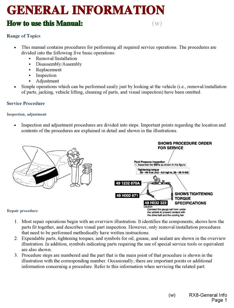
Range of Topics
• This manual contains procedures for performing
all required ser ice operations. The procedures
are di ided into the following fi e basic operations:
(1) Remo al/Installation
(2) Disassembly/Assembly
(3) Replacement
(4) Inspection
(5) Adjustment
• Simple operations which can be performed easily
just by looking at the ehicle (i.e.,
remo al/installation of parts, jacking, ehicle
lifting, cleaning of parts and isual inspection)
ha e been omitted.
Service Procedure
Inspection, adjustment
• Inspection and adjustment procedures are di ided
into steps. Important points regarding the location
and contents of the procedures are explained in
detail and shown in the illustrations.
SHOWS PROCEDURE ORDER
FOR SERVICE
SHOWS TIGHTENING
TORQUE
SPECIFICATIONS
Cautio n
• C on nect th e gau ge sat from un der th e ve
hicle to preve nt contact w ith the drive belt
and the cooling fan.
W6UOOOWAO
00-00-2
GENERAL INFORMATION
Repair procedure
1. Most repair operations begin with an o er iew illustration. It identifies the components, shows how the parts fit
together and describes isual part inspection. Howe er, only remo al/installation procedures that need to be
performed methodically ha e written instructions.
2. Expendable parts, tightening torques and symbols for oil, grease, and sealant are shown in the o er iew
illustration. In addition, symbols indicating parts requiring the use of special ser ice tools are also shown.
3. Procedure steps are numbered and the part that is the main point of that procedure is shown in the illustration
with the corresponding number. Occasionally, there are important points or additional information concerning
a procedure. Refer to this information when ser icing the related part.
“Removal/Installation”
Portion
“Inspection After
Installation” Portion
SHOWS SERVICE
ITEM (S)
/
LOWER TRAIUNG UNK. UPPER TRAILING LINK REMOVAL/INSTALLATION
1. Jack up the rear of the ehicle and support it with safety stands.
2. Remo e the underco er. (Refer to UNDERCOVER REMOVAL.) (Refer to UNDERCOVER INSTALLATION.)
3. Remo e in the order indicated in the table.
4. Install in the re erse order of remo al.
Indicates reie ant
references that need to be
followed during installation.
5. Inspect the rear wheel alignment and adjust it if necessary.
Install the parts
by performing
steps 1 3 In
reverse order
SHOWS PROCEDURE ORDER
FOR SERVICE
SHOWS TIGHTENING
TORQUE
SPECIFICATIONS
SHOWS SPECIAL
SERVICE TOOL (SST)
FOR SERVICE OPERATION
SHOWS APPLICATION
POINTS OF GREASE, ETC.
SHOWS EXPENDABLE PARTS
»4-116 {«.5-11.®, «*-8«) 111-15« <«2.0-ie.0.17-115)
®D
SHOWS DETAILS
SHOWS TIGHTENING
TORQUE UNITS
SHOWS REFERRAL
NOTES FOR SERVICE H-m { kgt-m, frlb f}
1Split pin
VNut
3 s hvtow er trailina link ball joint
L y Re mo val N ote I
4Bolt
5Lo wer trailing link
6D ust boo t (lower trailing link)
* r Installation N ote
7 Split pin
8 Nut
9Upper trailing link ball joint
Rem oval Note
10 Nut
11 Upper trailing link
12 Dust boot (upper trailing link)
Rem oval Note
Lower Trailing Link Ball Joint, Upper Trailing Link
Ball Joint Removal Note
• Remove the ball Joint by using the SSTa.
49 T028 304
4 9 T0 28 30 5
UPPER TRAIUN G LINK
LOW ER T RAIUN G UNK
SHOWS SPECIAL
SERVICE TOOL (SST)
NO. W*».|11r*u
SHOWS REFERRAL
NOTES FOR
SERVICE
W6UOOOWA1
00-00-3
GENERAL INFORMATION
Symbols
• There are eight symbols indicating oil, grease,
fluids, sealant and SST use. These symbols show
application points or use of these materials during
ser ice.
Advisory Messages
You’ll find se eral Warnings, Cautions, Notes,
Specifications and Upper and Lower Limits in this
manual.
Warning
• A Warning indicates a situation in which
serious injury or death could result if the
warning is ignored.
Caution
• A Caution indicates a situation in which
damage to the vehicle could result if the
caution is ignored.
Note
• A Note pro ides added information that will
help you to complete a particular procedure.
Specification
• The alues indicate the allowable range when
performing inspections or adjustments.
Upper and Lower Limits
• The alues indicate the upper and lower limits that
must not be exceeded when performing
inspections or adjustments.
Troubleshooting Procedure
Basic flow of troubleshooting
W 6 U O O O W A A
On-board diagnosis
• Diagnostic trouble codes (DTCs) are important
hints for repairing malfunctions that are difficult to
simulate. Perform the specific DTC diagnostic
inspection to quickly and accurately diagnose the
malfunction.
• The on-board diagnostic function is used during
inspection. When a DTC is shown specifying the
cause of a malfunction, continue the diagnostic
inspection according to the items indicated by the
on-board diagnostic function.
Engine tune-up (section 01)
• Any necessary adjustments are made after
starting the engine.
Basic inspection (section 05)
• The basic inspection is performed to quickly
narrow down the possible causes of a malfunction
regardless of symptoms. Also, basic inspection is
performed to locate the area(s) of any
malfunction.
Symbol Meaning Kind
rW 6 U O O O W A 2
Apply oil New appropriate
engine oil or gear
oil
W 6 U 0 0 0 W A 3
Apply brake fluid New appropriate
brake fluid
O
W 6 U 0 0 0 W A 4
Apply automatic
transaxle/
transmission fluid
New appropriate
automatic
transaxle/
transmission fluid
“ i
1
W 6 U O O O W A 5
Apply grease Appropriate
grease
W 6 U 0 0 0 W A 6
Apply sealant Appropriate
sealant
o
W 6 U 0 0 0 W A 7
Apply petroleum
jelly Appropriate
petroleum jelly
o
W 6 U 0 0 0 W A 8
Replace part O-ring, gasket,
etc.
a
V 6 U 0 0 0 W A 9
Use SST Appropriate SST
00-00-4
GENERAL INFORMATION
Diagnostic index Symptom troubleshooting
• The diagnostic index lists the symptoms of • Symptom troubleshooting quickly determines the
specific malfunctions. Select the symptoms location of the malfunction according to symptom
related or most closely relating to the malfunction. type.
Quick diagnosis chart (section 01 and 05)
• The quick diagnosis chart lists diagnosis and
inspection procedures to be performed specifically
relating to the cause of the malfunction.
Procedures for Use
Using the basic inspection
• Perform the basic inspection procedure before symptom troubleshooting.
• Perform each step in the order shown.
• The reference column lists the location of the detailed procedure for each basic inspection.
• Although inspections and adjustments are performed according to the reference column procedures, if the
cause of the malfunction is disco ered during basic inspection, continue the procedures as indicated in the
remarks column.
SHOWS INSPECTION
ORDER
REFERENCE
COLUMN
SHOWS ITEM NAMES FOR
DETAILED PROCEDURES SHOW POINTS REQUIRING
ATTENTION BASED ON
INSPECTION RESULTS
STEP
1
INSPECTION
Turn ignition switch to ON
Does hold indicator light (illumindfe/go out)
correspond to hold switch position (ON/OFF)?
Check the ATF color and condition
Are ATF color and odor normal?
Perform the line pressure test
B3’ MECHANICAL SYSTEM TEST, Line
Pressure Test
Is line pressure OK?
Perform the stall test
B3“ MECHANICAL SYSTEM TEST, Stall Test
Is stall speed OK?
Yes
No
Yes
No
Yes
No
Yes
No
ACTION
Go to next step
Perform malfunction diagnosis according to No.26 'H(
INDICATOR LIGHT DOES NOT ILLUMINATE WHEN
HOLD SWITCH IS TURNED ON" or No.27 ‘HOLD
INDICATOR LIGHT ILLUMINATES WHEN HOLD SWITCH
IS NOT TURNED ON"
Go to next step
Repair or replace any defecii e parts
Go to next step
Repair or replace any defecti e parts
Go to next step
Repair or replace any defecti e parts
Perform symptom troubleshooting
W 6 U O O O W A B
Using the diagnosis index
• The symptoms of the malfunctions are listed in the diagnostic index for symptom troubleshooting.
• The exact malfunction symptoms can be selected by following the index.
N o . T R O U BL E S H O O TIN G ITE M D E SC R IP TIO N
1 Discharged battery
2W ill not crank or cranks slowly -
3No combustion Engine cranks at normal speed but show s on sign of firing
4Com bustion observed but eng ine will not start Engine show s combustion while cranking but will not continue
to run when ignition switch is turned from STA to O N
5 C rank s norm al by hard to start
Engine cranks at normal sp eed but requires excessive cran k
ing time before starting
Engine runs normally at idle after started
6Low idle sp eed/Eng ine stalls or vibrates Engines idles at low speeo, stalls, or vib rates wh en engine is
cold, hot. or normal temperature
7High idle speed
Idle speed hard to high
Idle speed excessively high and will not go d ow n after w arm 
up
8High idle speed
Idle speed hard to low er
Idle speed excessively high and requires tim e to b e low ered to
norm al sp eed after w arm -up
9Rough idle/Engine stalls when E/L, P/S, or
A /C O N
Engine runs normally at idle with no load but stalls or vibrates
excessively when load (E/L. P /S . or A /C) is O N
1 0 ^ Engine runs normally at idle but stalls or vibrates excessively
during N -D shift
00-00-5
GENERAL INFORMATION
Using the quick diagnosis chart
The chart lists the relation between the symptom and the cause of the malfunction.
The chart is effecti e in quickly narrowing down the relation between symptom and cause of the malfunction.
It also specifies the area of the common cause when multiple malfunction symptoms occur.
The appropriate diagnostic Inspection relating to malfunction cause as specified by the symptoms can be
selected by looking down the diagnostic inspection column of the chart.
PART WHICH MAY BE
THE SYMPTOM PARTS WHICH MAY BE THE CAUSE OF
PROBLEMS
© CHOOSE THE ACTUAL
SYMPTOM
<D DETERMINE THE
CAUSE OF THE
TROUBLE DETERMINED .
AT PROCEDURE ©, <
BASED ON THE RESULT '
OF THE MECHANICAL
SYSTEM TEST
Discharged batlery \ !
2Will not Crank or cranks slowly \ j
3No combustion \ D O o o o O o c o o
4CamDusnon observed engine will not sian b o C c00 0 0 0 0 0 0!00 o o 0
5 Cranks normally but hard to Stan c 0
6 Low Kfle speed/Engme stalls or vebrates o o 0cO o o o o o o o o oo0 o o o
7High idle speed o o o
8icle speed hard to lower oo
9Rouqh Idle/Engine stalls when E/L. P/S or
ATC ON 0 o
10 Rough ¿die/Engine stalls during N -0 shiti oo
11 Engine stalls when vehicle about 10 run o
:;\ Z ' Engine stalls on acceleration and while
cru ising- 13 0 o o o o
13 Poor acceieraiion/insulliaent power surges
while cruismg/Hesitaies 0 0 0 0O O 0 0 0 0 0 o 0 0 o o o
14 Runs rough during deceleration backi.rc opo
15 Knocking o O o o oo
16 Ove/heatmg 1 !
17 Poor luei economy o0 o o
18 Fuel odor 0o 0 o
No. Item / intake-air
system 8 Fuel system l l
1 »
S ?
l l
¿ 3
0
cn
n m
1 ?
Emission
control system Cooirol system
TrouWe
sympiom
Inspection
method
Item
/ Cause oi
\ trouDle
Result \
H
a
0
1
1
Ò
*
Ç
f t
3 0
!
0
1
i
s
I f
i f
> <A
* a
£ (/>
I «
I
I
i
s
a
o
Z
è
I
5 ?
Li. 2
I I
i t
1 »
8 ?
3 0
s
re
1
«
I
S?
£
I f
l ì
f i
Q.
1
J j
/S f I
2 « *
- I * 1
1 5 >
h l l
: 0. Œ O
s
«
5
<2
à
iO'
X
£
1
o
?
I f
5
Ic
j
& l l
s If f
_i G < <
Ü
2
5
1
a>
3
I
£
2
n
>
1
? ■
I I
I - 5
s Ï
1 \
I !
1 5
£
Vi
c
3
0
1
O
a>
<7>
1 S'
3 G
>
<9
>
>
o
a
& J
O >->
1 1
< <
§
s t
? 1
S E
! I
I
i
1
A
<t
5
I
1
2 1
I s
z £
8
i
tft
g
s
s.
1
!
o
f t
¡ 1
Spark plug
condition
inspection
Wet/carbon stuck on
specific plug 1 0 o o
Graysh white with speciitc
plug 1o o o
Wet/catbon stuck on a« plus s0 0 oo O
Grayish white aH plugs ]0oo 0o o o
Cylinder balance
test Engine speed will not der-
ease ooo
Diagnosis trouble
code inspection Diagnostic trouWe code(s)
output o o
inspection usmg
oscilloscope induction voltage not gener
ated { 1 oo
THE PART CAUSING TROUBLE, AS DETERMINED FROM THE
RESULT OF THE MECHANICAL SYSTEM TEST.
W6U000WAD
00-00-6
GENERAL INFORMATION
Using the symptom troubleshooting
• Symptom troubleshooting shows diagnostic procedures, inspection methods, and proper action to take for
each trouble symptom.
TROUBLESHOOTING
HINTS describes possible
point of malfunction. TROUBLE SYMPTOM
STEP shows the
order of
troubleshooting.
INSPECTION describes
the method to quickly
determine the failed
part.
Reference item(s) for
additional information
to perform
INSPECTION.
9 | En gine sta lls /
tro u ble sh o o tin g hints
• C onstant application of torque converter clutch piston
S TE P IN S P E C TIO N A C T IO N
1C oes the vehicle shake at shift point as well as at
othe r points w hen decelerating? Yes Troubleshoot according to "Vehicle vibrates bac k and forth
or engine staiis during d ec eleration' ' - - ^
No G o to step 2.
2
/
C h ec k the voltage at the following powertrain con
tro l m od ule terminal.
• B rake sw itch signal
zt 01 -4 0 P O W E RT RA IN C O N TR O L M OD U L E
(PC M) IN S P EC TIO N
Is terminal voltage OK ?
Yes G o to step 3.
No Carry out the stall test,
c r 0 5 -1 7 M EC HA N IC A L S Y S TE M TE ST . StaH .
Test, Stall test procedure \
3 Does torque co nverter clutch solenoid valve volt
age at powertrain control m odule term inal m e a
sure 0 V ? ..
......
.
/ X T 0 1 -4 0 P O W E RTR AIN C ON TR O L MO D ULE
/ (PC M) IN SP EC T IO N
Y'es G o to step 4. \
No C heck for poor connection of the connectors from power
train control m odule lo torque converter clutch solenoid
valvs.
Che ck if torque converter clutch solenoid valve is
sticking.
Is solenoid va lve OK ?
Yes G o to step 5.
No R eplace torque converter clutch solenoid valve.
50 v e r h a u ljIie -A 3 ^ - *
---------------
-
«atignjof torque Yes G o to step 6.
No Repair or replace torque converter clutch control v alvtp v'-^
control valve body.
ACTION describes the
appropriate action to
take (Yes/No) based
INSPECTION result.
Reference item(s) to
perform ACTION.
W6U000WAE
Text Sequence
• The text sequence is indicated by the arrows shown below.
Example:
W6UOOOWAF
KE-AIR SYSTEM
00-00-7
GENERAL INFORMATION
W6UOOOWO2
Conversion to SI Units (Systèm e International
d’Unités)
• All numerical alues in this manual are based on
SI units. Numbers shown in con entional units are
con erted from these alues.
Rounding Off
• Con erted alues are rounded off to the same
number of places as the SI unit alue. For
example, if the SI unit alue is 17.2 and the alue
after con ersion is 37.84, the con erted alue will
be rounded off to 37.8.
Upper and Lower Limits
• When the data indicates upper and lower limits,
the con erted alues are rounded down if the SI
unit alue is an upper limit and rounded up if the
SI unit alue is a lower limit. Therefore, con erted
alues for the same SI unit alue may differ after
con ersion. For example, consider 2.7 kgf/cm2 in
the following specifications:
210 260 kPa {2.1 2.7 kgf/cm 2, 30 38 psi}
270 310 kPa {2.7 3.2 kgf/cm2, 39 45 psi}
• The actual con erted alues for 2.7 kgf/cm2 are
264 kPa and 38.4 psi. In the first specification, 2.7
is used as an upper limit, so the con erted alues
are rounded down to 260 and 38. In the second
specification, 2.7 is used as a lower limit, so the
con erted alues are rounded up to 270 and 39.
SAE STANDARDS W6UOOOWO3
• In accordance with new regulations, SAE (Society of Automoti e Engineers) standard names and
abbre iations are now used in this manual. The table below lists the names and abbre iations that ha e been
used in Mazda manuals up to now and their SAE equi alents.
Previous Standard New Standard
Abbr. Name Abbr. Name Remark
Accelerator Pedal AP Accelerator Pedal
Air Cleaner ACL Air Cleaner
Air Conditioning A/C Air Conditioning
— Airflow Meter VAF Volume Air Flow Sensor
Airflow Sensor MAF Mass Air Flow Sensor
Alternator GEN Generator
—ATF Thermosensor — Transmission (Transaxle) Fluid
Temperature Sensor
Atmospheric Pressure BARO Barometric Pressure
VB Battery Voltage B+ Battery Positi e Voltage
UNITS
Electrical current A (ampere)
Electric potential V ( olt)
Electric power W (watt)
Length mm (millimeter)
in (inch)
Negati e pressure
kPa (kilo pascal)
mmHg (millimeters of mercury)
inHg (inches of mercury)
Positi e pressure
kPa (kilo pascal)
kgf/cm2 (kilogram force per square
centimeter)
psi (pounds per square inch)
Resistance Q (ohm)
Torque
Nm (Newton meter)
kgf-m (kilogram force per meter)
kgf-cm (kilogram force per centimeter)
ft lbf (foot pound)
in-lbf (inch pound)
Volume
L (liter)
US qt (U.S. quart)
Imp qt (Imperial quart)
ml (milliliter)
cc (cubic centimeter)
cu in (cubic inch)
fl oz (fluid ounce)
Weight g (gram)
oz (ounce)
00-00-8
GENERAL INFORMATION
Previous Standard New Standard
Abbr. Name Abbr. Name Remark
—Catalytic Con erter
OC Oxidation Catalytic Con erter
TWC Three Way Catalytic Con erter
WU-TWC Warm Up Three Way Catalytic
Con erter Directly connected to
exhaust manifold
—Circuit Opening Relay FPR Fuel Pump Relay
In some models, there is a
fuel pump relay that
controls pump speed. That
relay is now called the fuel
pump relay (speed).
—Clutch Position CPP Clutch Pedal Position
—Crank Angle Sensor CMP Camshaft Position Sensor
—Crank Angle Sensor 2 CKP Crankshaft Position Sensor
—Diagnosis Connector DLC Data Link Connector
—Diagnosis/Self-Diagnosis OBD On-Board Diagnostic
—Direct Ignition DLI Distributorless Ignition
—EC-AT Control Unit TCM Transmission (Transaxle) Control
Module
EGI Electronic Gasoline Injection
System CIS Continuous Fuel Injection
System
— Electronic Spark Ignition El Electronic Ignition Controlled by the
ECM/PCM
ECU Engine Control Unit PCM Powertrain Control Module De ice that controls engine
and powertrain
ECM Engine Control Module
—Engine Modification EM Engine Modification
—Engine RPM Signal —Engine Speed Input Signal
— E aporati e Emission EVAP E aporati e Emission
— Exhaust Gas Recirculation EGR Exhaust Gas Recirculation
— Fan Control FC Fan Control
— Feedback System CLS Closed Loop System
—Flexible Fuel FF Flexible Fuel
—Fuel Pump FP Fuel Pump
— Fully Closed CTP Closed Throttle Position
—Fully Open WOT Wide Open Throttle
—Ground/Earth GND Ground
— 1C Regulator VR Voltage Regulator
— Idle Speed Control IAC Idle Air Control
—Idle Switch —Closed Throttle Position Switch
— Igniter ICM Ignition Control Module
—Inhibitor TR Transmission (Transaxle) Range
— Intake Air Pressure MAP Manifold Absolute Pressure
—Intake Air Thermo IAT Intake Air Temperature
—Intercooler CAC Charge Air Cooler
—Knock Sensor KS Knock Sensor
—Line Pressure Solenoid Val e —Pressure Control Solenoid
—Lock-up TCC Torque Con erter Clutch
—Malfunction Indicator Light MIL Malfunction Indicator Lamp
—Multiport Fuel Injection MFI Multiport Fuel Injection
—Open Loop OL Open Loop
—O erdri e 4GR Fourth Gear
00-00-9
GENERAL INFORMATION
Previous Standard New Standard
Abbr. Name Abbr. Name Remark
—Oxygen Sensor H02S Heated Oxygen Sensor With heater
02S Oxygen Sensor
— Park/Neutral Range PNP Park/Neutral Position
— Power Steering Pressure PSP Power Steering Pressure
—Pulse Generator —Input/Turbine Speed Sensor
— Reed Val e SAPV Secondary Air Pulse Val e
—Secondary Air Injection System PAIR Pulsed Secondary Air Injection Pulsed injection
AIR Secondary Air Injection Inject with compressor
—Sequential Fuel Injection SFI Sequential Multipoint Fuel
Injection
— Ser ice Code(s) DTC Diagnostic Trouble Code(s)
— Spark Ignition Dl Distributor Ignition
—Stoplight Switch —Brake Switch
—Test Mode DTM Diagnostic Test Mode Diagnostic trouble codes
depend on the diagnostic
test mode
—Throttle Body TB Throttle Body
—Throttle Sensor TP Throttle Position Sensor
—Turbocharger TC Turbocharger
—Vehicle Speed Sensor VSS Vehicle Speed Sensor
—Vehicle Speed Sensor 1 — Output Speed Sensor
—Water Thermo ECT Engine Coolant Temperature
—1-2 Shift Solenoid Val e —Shift Solenoid A
Shift + A Solenoid Val e
—2-3 Shift Solenoid Val e —Shift Solenoid B
Shift + B Solenoid Val e
—3-4 Shift Solenoid Val e —Shift Solenoid C
—3rd Gear 3GR Third Gear
———Incorrect Gear Ratio
FUNDAMENTAL PROCEDURES W6U0O0W04
Protection of the Vehicle Preparation of Tools and Mesuring Equipment
• Always be sure to co er fenders, seats and floor • Be sure that all necessary tools and measuring
areas before starting work. equipment are a ailable before starting any work.
W6U000WAH
00-00-10
GENERAL INFORMATION
Special Tools
• Use special tools when they are required.
W6UOOOWAJ
Disconnection of the Negative Battery Cable
• Before beginning any work, turn the ignition switch
to LOCK, disconnect the negati e battery cable
and then wait for more than 1 minute to allow the
backup power supply of the SAS unit to deplete its
stored power.
Removal of Parts
• While correcting a problem, also try to determine
its cause. Begin work only after first learning
which parts and subassemblies must be remo ed
and disassembled for replacement or repair. After
remo ing the part, plug all holes and ports to
pre ent foreign material from entering.
W6U000WAK
Disassembly
• If the disassembly procedure is complex requiring
many parts to be disassembled, all parts should
be disassembled in a way that will not affect their
performance or external appearance and identified
so reassembly can be performed easily and
efficiently.
W6UOOOWAL
Arrangement of Parts
• All disassembled parts should be carefully
arranged for reassembly.
• Be sure to separate or otherwise identify the parts
to be replaced from those that will be reused.
Cleaning of Parts
• All parts to be reused should be carefully and
thoroughly cleaned in the appropriate method.
Warning
• Using compressed air can cause dirt and
other particles to fly out causing injury to
the eyes. Wear protective eye wear
whenever using compressed air.
Inspection During Removal, Disassembly
• When remo ed, each part should be carefully
inspected for malfunctioning, deformation,
damage and other problems.
W 6 U 0 0 0 W A M
W6U000WAN
W6U000WAP
00-00-11
GENERAL INFORMATION
Reassembly
• Standard alues, such as torques and certain
adjustments, must be strictly obser ed in the
reassembly of all parts.
If remo ed, these parts should be replaced with
new ones:
• Oil seals
• Gaskets
• O-rings
• Lockwashers
• Cotter pins
• Nylon nuts
W 6 U 0 0 0 W A Q
W 6 U O O O W A T
Hose Clamps
• When reinstalling, position the hose clamp in the
original location on the hose and squeeze the
clamp lightly with large pliers to ensure a good fit.
Depending on location:
• Sealant and gaskets, or both, should be applied to
specified locations. When sealant is applied, parts
should be installed before sealant hardens to
pre ent leaks.
• Oil should be applied to the mo ing components
of parts.
• Specified oil or grease should be applied at the
prescribed locations (such as oil seals) before
reassembly.
W 6 U 0 0 0 W A U
Torque Formulas
• When using a torque wrench-SST combination,
the written torque must be recalculated due to the
extra length that the SST adds to the torque
wrench. Recalculate the torque by using the
following formulas. Choose the formula that
applies to you.
Adjustments
• Use suitable gauges and testers when making
adjustments.
Torque Unit Formula
N-m N-m x [LV(L+A)j
kgf-m kgf-m x [L/(L+A)j
kgf-cm kgf-cm x [L/(L+A)j
ftlbf ft lbf x [L/(L+A)j
in-lbf in-lbf x [L/(L+A)j
A : The length of the SST past the torque wrench dri e.
L : The length of the torque wrench.
W6U000WAS
00-00-12
W 6 U O O O W A R
Rubber Parts and Tubing
• Pre ent gasoline or oil from getting on rubber
parts or tubing.
GENERAL INFORMATION
Vise
• When using a ise, put protecti e plates in the
jaws of the ise to pre ent damage to parts.
W6U000WAW
Dynamometer
• When test-running a ehicle on a dynamometer:
• Place a fan, preferably a ehicle-speed
proportional type, in front of the ehicle.
• Connect an exhaust gas entilation unit.
• Cool the exhaust pipes with a fan.
• Keep the area around the ehicle uncluttered.
• Watch the water temperature gauge.
Note
• When the ehicle is on a chassis roller and
only the front wheels rotate, the ABS warning
light may illuminate. Refer to 04-01
PRECAUTION to turn off the warning light.
INSTALLATION OF RADIO SYSTEM
If a radio system is installed improperly or if a
high-powered type is used, the CIS and other
systems may be affected. When the ehicle is to be
equipped with a radio, obser e the following
precautions:
1. Install the antenna at the farthest point from
control modules.
W 6 U 0 0 0 W 0 5
2. Install the antenna feeder as far as possible from
the control module harnesses.
3. Ensure that the antenna and feeder are properly
adjusted.
4. Do not install a high-powered radio system.
ELECTRICAL SYSTEM
Electrical Parts
Battery cable
• Before disconnecting connectors or remo ing
electrical parts, disconnect the negati e battery
cable.
W6U000W06
W6U000WAX
Disconnecting connectors
• When disconnecting two connectors, grasp the
connectors, not the wires.
Connectors
Data link connector
• Insert the probe into the ser ice hole when
connecting a jumper wire to the data link
connector.
Caution
• Inserting a jumper wire probe into the data
link connector terminal may damage the
terminal.
W 6 U O O O W A Y
W 6 U O O O W A Z
00-00-13
GENERAL INFORMATION
Connectors can be disconnected by pressing or
pulling the lock le er as shown.
W6U000WB3
W6UOOOWBO
Locking connector
• When locking connectors, listen for a click
indicating they are securely locked.
Terminals
Inspection
• Pull lightly on indi idual wires to check that they
are secured in the terminal.
W6U000WB4
inspection
• When a tester is used for checking continuity or
measuring oltage, insert the tester probe from
the wiring harness side.
W6U000WB2
Check the terminals of waterproof connectors
from the connector side since they cannot be
accessed from the wiring harness side.
Caution
• To prevent damage to the terminal, wrap a
thin wire around the lead before inserting
into terminal.
Replacement
• Use the appropriate tools to remo e a terminal as
shown. When installing a terminal, be sure to
insert it until it locks securely.
• Insert a thin piece of metal from the terminal side
of the connector and with the terminal locking tab
pressed down, pull the terminal out from the
connector.
00-00-14
GENERAL INFORMATION
/ ' “ 'N
Sensors, Switches, and Relays
• Handle sensors, switches and relays carefully. Do
not drop them or strike them against other objects.
Wiring Harness
Wiring color codes
• Two-color wires are indicated by a two-color code
symbol.
• The first letter indicates the base color of the wire
and the second the color of the stripe.
CODE COLOR CODE COLOR
BBlack 0 Orange
BR Brown P Pink
G Green R Red
GY Gray V Violet
L Blue W White
LB Light Blue Y Yellow
LG Light Green
B/R BR/Y
BLACK
RED
Fuse
Replacement
• When replacing a fuse, be sure to replace it with
one of the same capacity. If a fuse fails again, the
circuit probably has a short and the wiring should
be checked.
• Be sure the negati e battery terminal is
disconnected before replacing a main fuse.
When replacing a pullout fuse, use the fuse puller.
W6U000WB9
Electrical Troubleshooting Tools
Jumper wire
• A jumper wire is used to create a temporary
circuit. Connect the jumper wire between the
terminals of a circuit to bypass a switch.
Caution
• Do not connect a jumper wire from the
power source line to a body ground. This
may cause burning or other damage to
wiring harnesses or electronic
components.
00-00-15
GENERAL INFORMATION
Voltmeter
• The DC oltmeter is used to measure circuit
oltage. A oltmeter with a range of 15 V or more
is used by connecting the positi e (+) probe (red
lead wire) to the point where oltage will be
measured and the negati e (-) probe (black lead
wire) to a body ground.
Caution
• Do not connect the ohmmeter to any
circuit where voltage is applied. This will
damage the ohmmeter.
VOLTMETER POWER SOURCE LINE
Ohmmeter
• The ohmmeter is used to measure the resistance
between two points in a circuit and to check for
continuity and short circuits.
JACKING POSITIONS
Warning
• Improperly jacking a vehicle is dangerous.
The vehicle can slip off the jack and cause
serious injury. Use only the correct front
and rear jacking positions and block the
wheels.
Use safety stands to support the ehicle after it has
been lifted.
Front
• At the center of the crossmember
W6UOOOWO7
Rear
• At the center of the crossmember
00-00-16
GENERAL INFORMATION
VEHICLE LIFT (2 SUPPORTS) AND SAFETY STAND (RIGID RACK) POSITION W6UOOOWO8
Vehicle Lift Positions
Front
• Both sides of the ehicle, on side silis.
Safety Stand Positions
Front
• Both sides of the ehicle, on side sills.
Rear
• Both sides of the ehicle, on side sills.
Rear
• Both sides of the ehicle, on side sills.
W 6 U 0 0 0 W 0 9
Caution
• Do not tow the vehicle backward with
driving wheels on the ground. This may
cause internal damage to the transaxle.
WHEEL DOLLIES
W6U000WBL
Proper lifting and towing are necessary to pre ent
damage to the ehicle. State and local laws must be
followed.
A towed ehicle usually should ha e its front wheels
off the ground. If excessi e damage or other
conditions pre ent this, use wheel dollies.
When towing with the rear wheels on the ground,
release the parking brake.
W 6 U 0 0 0 W B K
00-00-17
GENERAL INFORMATION
Caution
• Do not tow with sling-type equipment.
This could damage your vehicle. Use
wheel-lift or flatbed equipment.
Caution
• Do not use the hook loops under the front
and rear bumpers for towing. They are
designed ONLY for tying down the vehicle
when it’s being transported. Using them
for towing will damage the bumper.
Tiedown Hooks
Front
Rear
IDENTIFICATION NUMBER LOCATIONS
Vehicle Identification Number (VIN) Chassis Number
W6U000WBV
W 6 U O O O W B P
W 6 U 0 0 0 W B Q
W6UOOOWIO
W6U000WBR
00-00-18

Other Mazda Automobile manuals

Mazda 2014 CX-5 Guide

Mazda

Mazda 2014 CX-5 Guide

Mazda Mazda 6 Guide

Mazda

Mazda Mazda 6 Guide

Mazda 2006 3 Assembly instructions

Mazda

Mazda 2006 3 Assembly instructions

Mazda 2007 Mazdaspeed 3 Guide

Mazda

Mazda 2007 Mazdaspeed 3 Guide

Mazda 2007 B2300 Truck User manual

Mazda

Mazda 2007 B2300 Truck User manual

Mazda CX-30 User manual

Mazda

Mazda CX-30 User manual

Mazda 2009 CX-9 Guide

Mazda

Mazda 2009 CX-9 Guide

Mazda B-Series 1997 Instruction manual

Mazda

Mazda B-Series 1997 Instruction manual

Mazda 2009 B2300 Truck Guide

Mazda

Mazda 2009 B2300 Truck Guide

Mazda 2 User manual

Mazda

Mazda 2 User manual

Mazda 2009 CX-9 User manual

Mazda

Mazda 2009 CX-9 User manual

Mazda MX-5 Miata Assembly instructions

Mazda

Mazda MX-5 Miata Assembly instructions

Mazda 1979-1984 RX7 Reference manual

Mazda

Mazda 1979-1984 RX7 Reference manual

Mazda CX-9 2019 User manual

Mazda

Mazda CX-9 2019 User manual

Mazda 2013 MX-5 Miata Guide

Mazda

Mazda 2013 MX-5 Miata Guide

Mazda 2013 2 User manual

Mazda

Mazda 2013 2 User manual

Mazda 2009 6 User manual

Mazda

Mazda 2009 6 User manual

Mazda 2010 CX-7 User manual

Mazda

Mazda 2010 CX-7 User manual

Mazda 2002 Tribute Assembly instructions

Mazda

Mazda 2002 Tribute Assembly instructions

Mazda car Instruction manual

Mazda

Mazda car Instruction manual

Mazda CX-7 Navigation System Assembly instructions

Mazda

Mazda CX-7 Navigation System Assembly instructions

Mazda RX-7 1989 Service manual

Mazda

Mazda RX-7 1989 Service manual

Mazda 121 1991 Instruction manual

Mazda

Mazda 121 1991 Instruction manual

Mazda Tribute User manual

Mazda

Mazda Tribute User manual

Popular Automobile manuals by other brands

Toyota Corolla 2022 owner's manual

Toyota

Toyota Corolla 2022 owner's manual

Opel 2009 Meriva Brochure & specs

Opel

Opel 2009 Meriva Brochure & specs

Volvo V50 owner's manual

Volvo

Volvo V50 owner's manual

Mercedes-Benz S 55 AMG Operator's manual

Mercedes-Benz

Mercedes-Benz S 55 AMG Operator's manual

Vauxhall Insignia owner's manual

Vauxhall

Vauxhall Insignia owner's manual

BMW 2008 M3 owner's manual

BMW

BMW 2008 M3 owner's manual

Subaru IMPREZA GD 2007 Series manual

Subaru

Subaru IMPREZA GD 2007 Series manual

BMW X5 3.0I owner's manual

BMW

BMW X5 3.0I owner's manual

Dodge DURANGO 2021 owner's manual

Dodge

Dodge DURANGO 2021 owner's manual

Mahindra XUV500 2012 owner's manual

Mahindra

Mahindra XUV500 2012 owner's manual

HOLDEN VX Series 2000 Owner's handbook

HOLDEN

HOLDEN VX Series 2000 Owner's handbook

SMART fortwo Handbook

SMART

SMART fortwo Handbook

Volvo 2009 S60 owner's manual

Volvo

Volvo 2009 S60 owner's manual

Bricklin SV-1 1975 Service manual supplement

Bricklin

Bricklin SV-1 1975 Service manual supplement

Chevrolet 2013 Malibu owner's manual

Chevrolet

Chevrolet 2013 Malibu owner's manual

Lexus 2015 LX 570 owner's manual

Lexus

Lexus 2015 LX 570 owner's manual

Toyota Prius 2007 Important information

Toyota

Toyota Prius 2007 Important information

Dodge CHALLENGER 2021 quick start guide

Dodge

Dodge CHALLENGER 2021 quick start guide

manuals.online logo
manuals.online logoBrands
  • About & Mission
  • Contact us
  • Privacy Policy
  • Terms and Conditions

Copyright 2025 Manuals.Online. All Rights Reserved.