ENGINE
10.Drive
pulley,
435211
601
This
pulley
has
the
followingdif-
ferencesfromthestock
version:
(1)
The
materialis
aluminum
alloy
toreduce
weightand
rotating
inertia.
(2)
Theoilseallip'scontactarea
has
been
treated
forwearre-
sistance.
(3)
Thediameter
is
90
mm.
11. Flywheel,4352
1
1755
Thisflywheelis fabricatedfrom
steelbut is significantlylighter
thanstock
to reducerotating
in-
ertia.
12. Needle
bearing,082278184
Theneedle
bearing
has
a higher
load
capacitytowithstand
severe
clutchengagements.
C. Intake
andexhaust
group.
1. Intake
manifold,
435213100
This
manifoldhas
thefollowing
features:
(1)
ltiscastfromaluminum
alloy.
(2)
lthas
beendesignedtoaccept
and
workwiththeDDW48lDA
carburetor.
andto match
an
engine
installation
angleof
4"40'.
(3)
The
length
of theintake
pas-
sages
has beendetermined
foroptimumtuningandeffi-
ciencyat
the
designedengine
speeds.
2. Gaskets,
rotorhousing
to
intake
manifold:
086278205
intakemanifoldto
carburetor:
. 086278206
3. Carburetorsupport,0862
78240
This
support
reducesthetransfer
of
engine
vibrationstothe
carbur-
etor and thereby
prevents
fuel
surgingandbubbling.
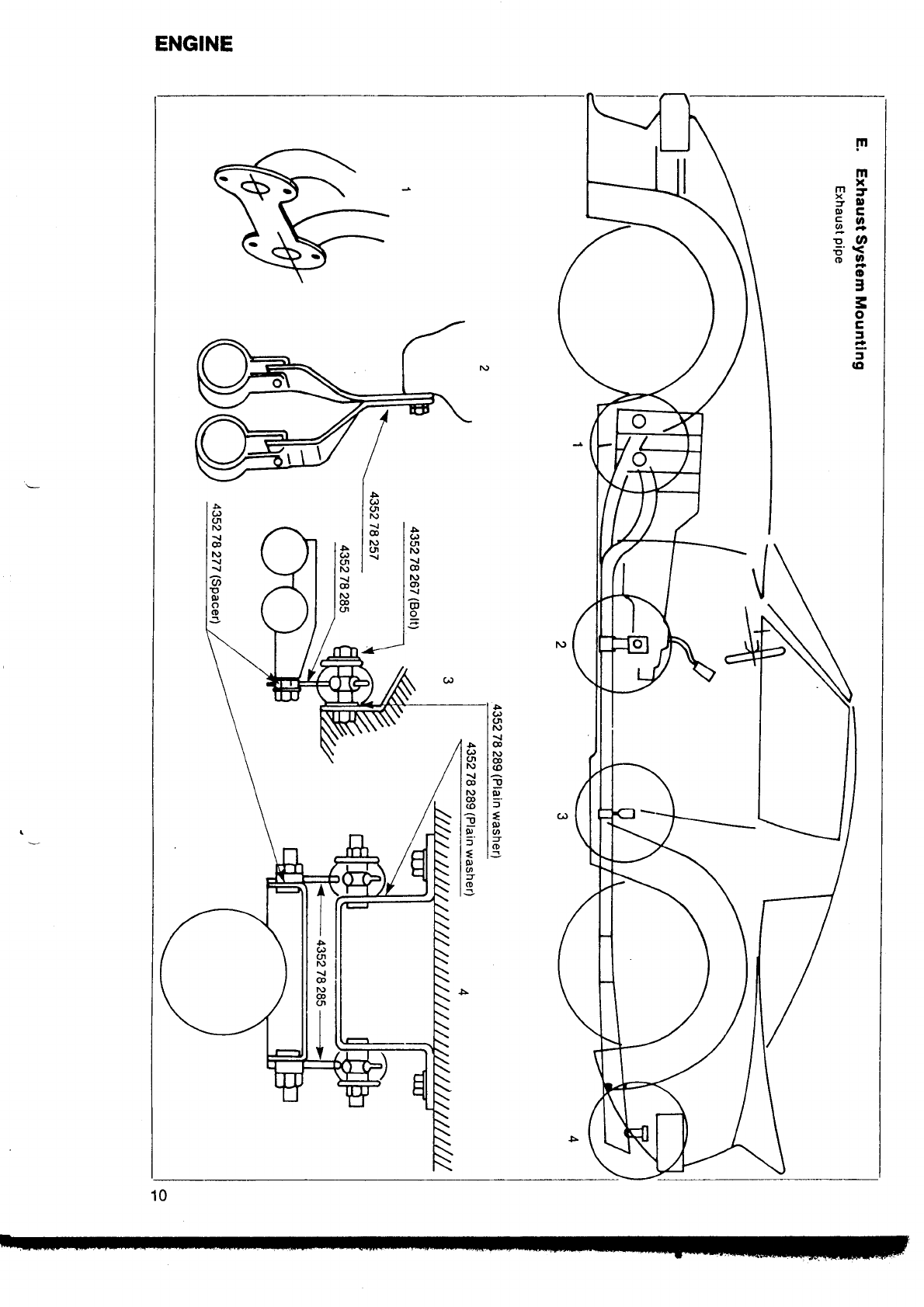
4. Exhaust
header
and
pipe,
header:
435278250
pipe:4352
78260
Someofthe
mainfeaturesof
exhaustsystemare:
(1)
Boththeheaderand
pipe
are
fabricatedfromstainlesssteel.
(2)
Theheader
is
atubulardesign,
andthe
pipe
terminatesin a
megaphone.
(3)
The
header
and
pipe
are
join-
edbya sliding
connectionto
allow
forengine
vibration
and
movement.
5. Exhaust
system
support
brackets
See
page
10for
details.
D. Lubrication
group.
1. Oil
pump,
105878
220A
Theshaft
and
rotorsin thecom-
petition
oil
pump
aremoreresis-
tanttowearandseizing.
Oil
pressure
regulator
assembly,
435214
250
Thisregulator
will maintain
oil
pressure
at
6.5
-r0.5
kg/cm'.
Engineoil
cooler,105878
180
This
larger-than-stock
coolerwill
increase
coolingcapacity
by 50
percent
over
stock.
E. Cooling
group.
1.Water
pump,4801
15
010
Thecompetitionwater
pump
is
aluminumalloy.
Water
pumppulley,4801
15151
To reduce
weightthis pulley
is
madefrom
aluminumalloy,and
itslarger-than-stock
130mmdia-
meter
will
enhanceV-belt
life
and
reduce
the speedof the water
pump.
Radiator,105878190
The
aluminumalloy
competition
radiator'slarger
corewill
increase
enginecoolingcapacity
by60
per-
cent
overstock.
V-belt,105878154
This
notchedV-beltismoreresis-
tantto
heat.
stretchand
vibration.
F. Electricalsystem.
1. lgnitioncoil,4801
1B100
This higheroutputcoil is exclu-
sively
designedfor use with the
Mazdacompetition
capacitivedis-
charge
ignition
(CDl).
2. Hightensionwires,
coil-to-distributor:43521B110
distributor-to-spark
pl
ugs:
48011B150
These
high
tensionwires
have
a
metalwire
coreto reducevoltage
drop.
3. Distributor,4B0l
1B200
Thesearethe mainfeaturesof the
distributor:
(1)
lt is breakerless,
havinga
magnetic
trigger.
(2)
Thereis no advance
mechan-
ism.
2.
3.
2.
3.