OUTLINE
Air conditioning operation & diagnosis course is 2-day training and centered on
Manual air conditioning system. Through this course, you can learn most frequent
services for air conditioning, such as Performance check, Refrigerant charge, and
Symptom troubleshooting.
The course begins with reviewing A/C Fundamentals (Mazda Masters Level F); you
are required to bring your textbook “A/C Fundamentals” to this training session.
Student guide and Student activity sheet are to be provided before the session starts.
In the Student guide and the Student activity sheet, you will find some questions and
tables that some information is intentionally removed. Try to answer to the question in
reference to what you have learnt so far and get information from relevant service
materials, such workshop manual and wiring diagram.
NOTE This course is developed based on the service materials of Mazda 3 included
in the CD-ESI (Electronic Service Information) 2/2004 Ver. 3.0 CD08-XX-04BE.
OBJECTIVES
After completing this course, you will be able to:
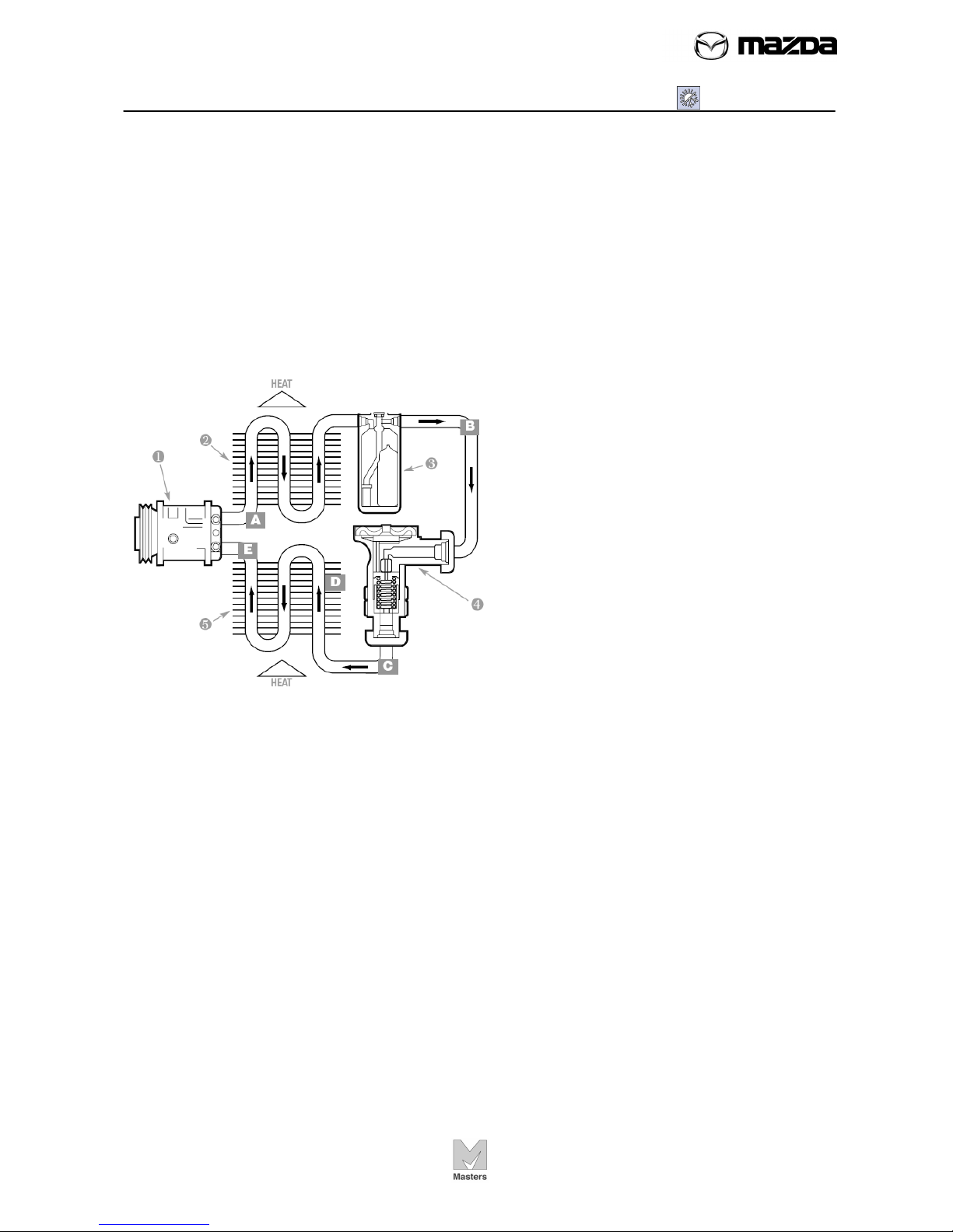
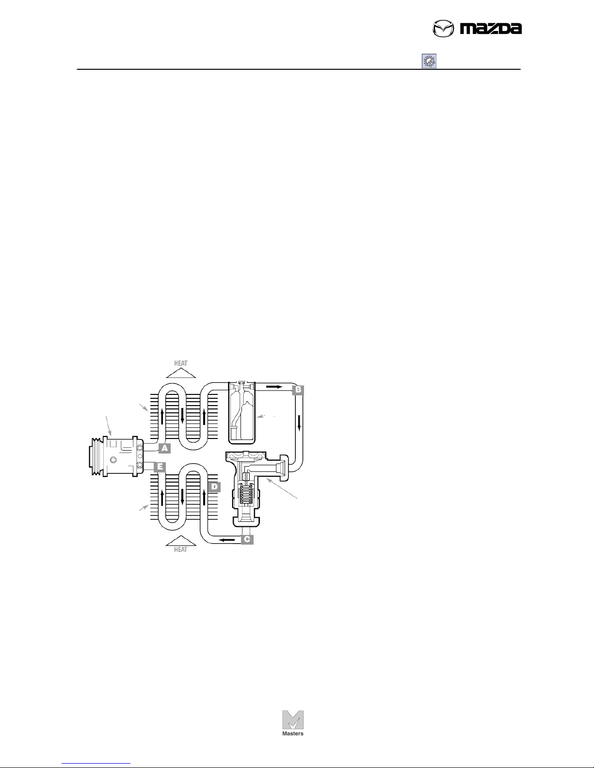
Describe a refrigeration cycle and what part the components play in the
cooling process.
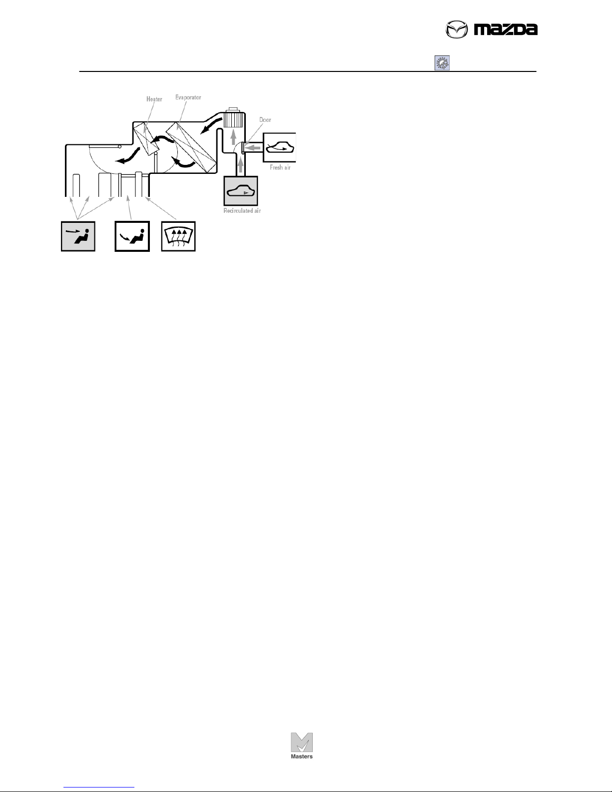
Identify major components of a manual A/C system
Identify the components of Manual Air Conditioner and distinguish the
components from those of Full-auto Air Conditioner.
Describe a control system and how the system controls the Manual Air
Conditioner.
Identify major components of a manual A/C system
Locate A/C system protection devices
Explain the function of protection devices
Conduct A/C performance checks
Perform A/C refrigerant charging
Perform checks for A/C components
Isolate trouble cause based on Symptom based approach