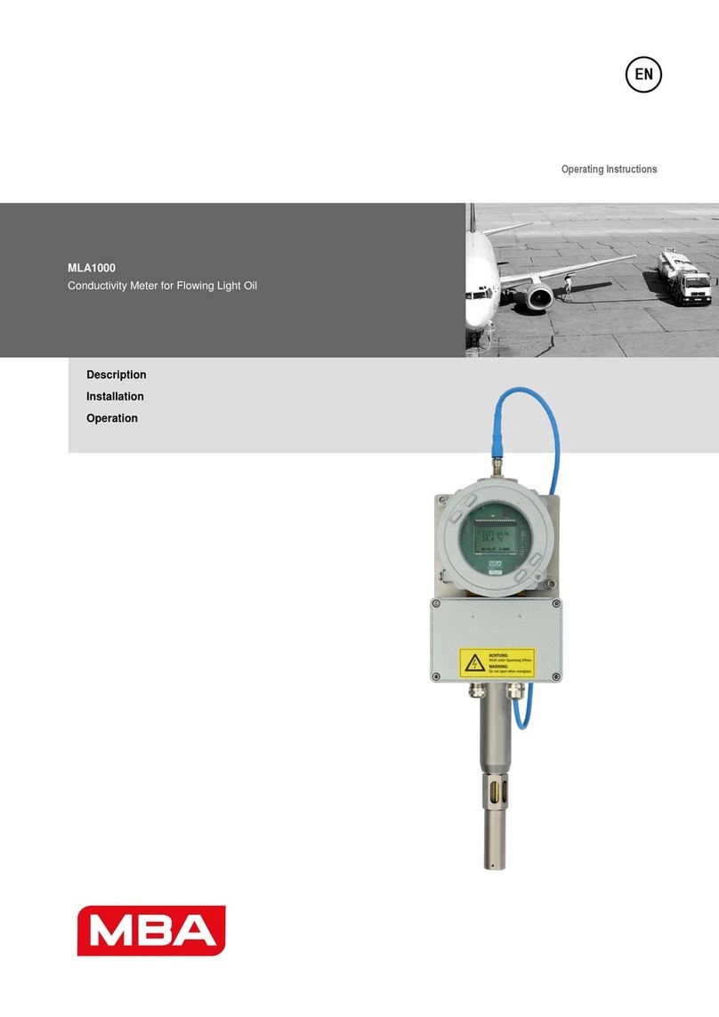
MBA MLA1000 User manual

Operating Manual
MLA1000
Conductivity meter
for light oils
Description
Installation
Operation

1 Operating Manual MLA1000 Date 19/05/2021· © MBA Instruments GmbH
Document information
Product described
Product name: MLA1000
Document identification
Title: Operating Manual MLA1000
Order No.: 8011707
Version: 1.0
Date: 19/05/2021
Publisher
MBA Instruments GmbH
Friedrich-List-Str. 3-7 · D-25451 Quickborn · Germany
Tel.: +49 (0) 41 06 123 888-0
Fax: +49 (0) 41 06 123 888-9
E-mail: info@mba-instruments.de
Warranty notice
Product characteristics and technical data presented in this
document do not constitute warranty statements.
© MBA Instruments GmbH. All rights reserved.
Warning symbols
WARNING
Danger to humans with the possible consequence of serious
injury or death
CAUTION
Danger with the possible consequence of less severe or minor
injury and/or danger or property damage.
Notice symbols
Important technical information
for this product
Important information for potentially
explosive atmospheres

Operating Manual ·MLA1000 Date 19/05/2021 © MBA Instruments GmbH 2
Contents
1Safety instructions 3
1.1 Safety instructions for use in potentially explosive atmospheres 3
2Product description 3
2.1 Use 3
2.2 Designation of the meter types according to their application 4
2.2.1 Meter types MZ and LZ for continuous inline measurement (stationary) 4
2.2.2 Meter types TX and TZ for temporary measurement 4
2.2.3 MLA1000-A display unit 5
2.2.4 Display elements 5
2.2.5 MLA1000-K probe cable 5
2.2.6 MLA1000-S probes 5
3Installation of the probes of meter types MZ and LZ 6
3.1 Notes on explosion protection for installation of the probes 6
3.2 Demands on the measurement liquid at the installation site 6
3.3 Positioning the measuring probe 6
3.4 Installation of probe tube in the sliding sleeve, meter type MZ 7
3.5 Installation of probe tube with collar and loose flange, meter type LZ 8
4Installation of the display unit, meter types MZ, LZ and TZ 8
4.1 Notes for the installation location within an Ex zone 8
4.2 The MLA1000 meter type TZ –additional requirements 8
4.3 Secure display unit with mounting plate 9
5Electrical connection of meter type TX and TZ 10
5.1 Cable installation, meter type TX and TZ 10
5.2 Probe cable for MLA1000 TX 10
5.3 Probe cable for MLA1000 TZ 10
6Electrical connection of meter types LZ, MZ and TZ 11
6.1 Notes on explosion protection for electrical connection 11
6.2 Cable installation 11
6.2.1 Terminal assignment 11
6.3 Connecting the probe cable 11
6.4 Connecting the measured value outputs 12
6.5 Supply voltage 12
6.6 Closing cable glands and housing 12
6.7 Connecting the equipotential bond 12
7Operation 13
7.1 Signs of a safe operating condition 13
7.2 Displays 13
7.3 Operating display 13
8Changing the measurement location with meter types TX and TZ 14
8.1 Notes on explosion protection for meter type TZ 14
8.2 Measuring process 14
9Maintenance 15
9.1 Notes on explosion protection for maintenance 15
9.2 Manual self-test 15
9.3 Calibration 15
9.4 Cleaning the measuring probe 16
9.5 Installing the probe again 16
10 Troubleshooting 17
10.1 Signs of an unsafe operating condition 17
10.2 Sensor error –Indication of an error on the MLA1000 display 17
10.3 Fatal error –Indication of an error on the MLA1000 display 17
10.4 Remedying faults 18
11 Technical data 19
11.1 MLA1000-S measuring probe 19
11.2 MLA1000-A display unit 19
11.3 MLA1000-K probe cable 19
11.4 Approval/suitability test (meter types: LZ, MZ, TZ) 19
12 Information on disposal 20

3 Operating Manual MLA1000 Date 19/05/2021· © MBA Instruments GmbH
1Safety instructions
Observe the following points for your own safety and for the safe operation of the meter:
Use the product only as described in this operating manual. The manufacturer assumes no responsible for any other
use.
Have repairs carried out only by the manufacturer or by trained and authorised specialists.
Do not remove, add or modify any components on the product unless described in official information from the
manufacturer. Any warranty of the manufacturer will otherwise be voided and the product may become dangerous.
Carry out the maintenance measures described.
Do not carry out any work or repairs on the product that are not described in this operating manual.
All local laws, engineering rules and operating instructions applicable at the place of use of the product must be
observed in addition to this operating manual.
Keep this operating manual and all other documents supplied in a safe place for future reference.
Pass on the documents to new owners.
1.1 Safety instructions for use in potentially explosive atmospheres
The MLA1000-A display unit and the MLA1000-S probe of meter types MZ, LZ and TZ operated in a potentially explosive
atmosphere must bear the following markings:
ATEX
MLA1000-A
II 2(1)G Ex de [ia Ga] IIB T4 Gb
BVS 14 ATEX E 047 X
ATEX
MLA1000-S
II 1G Ex ia IIB T4 Ga
BVS 14 ATEX E 026 X
IECEx
MLA1000-A
Ex db eb [ia Ga] IIB T4 Gb
IECEx BVS 21.0041X
IECEx
MLA1000-S
Ex ia IIB T4 Ga
IECEx BVS 21.0014 X
Use the MLA1000 in a potentially explosive atmospheres only if permitted by the specifications for zone, explosion
group and temperature class (see rating plates on display unit and measuring probe).
Observe and comply with the "special conditions" on the type examination certificate.
Have installation, commissioning, maintenance and testing carried out only by specialist staff who have the necessary
knowledge of the rules and regulations for potentially explosive atmospheres.
If individual information was supplied with the product: Give priority to the individual information.
Put the MLA1000 into operation only when all housings and all cable glands are correctly closed.
Have the MLA1000 installed and operated only by specialist staff who, through their specialist training and know-how
and their knowledge of the applicable regulations, are able to assess the work assigned to them and to recognise
hazards.
2Product description
2.1 Use
Measuring function
The MLA1000 measures the electrical conductivity and temperature of suitable measurement liquids. Suitable liquids
are liquids with an electrical conductivity of up to max. 15000 pS/m. The viscosity must also be taken into
consideration. Examples of suitable liquids are kerosene, light mineral oils, lubricants, hydraulic oils, rolling oils,
transformer oils, coolants and various chemical liquids. The conductivity is given in the physical unit “pS/m”
(picoSiemens per metre). The unit “c.u.” (conductivity unit) still widely used in the mineral oil industry is equivalent: 1
pS ⁄ m = 1 c.u.
Electrical conductivity and temperature
The electrical conductivity of liquids is heavily dependent on their temperature. The influence of the temperature on
the conductivity is not linear and is also substance-specific. It is therefore necessary to measure the temperature and
the electrical conductivity at the same time.

Operating Manual ·MLA1000 Date 19/05/2021 © MBA Instruments GmbH 4
2.2 Designation of the meter types according to their application
2.2.1 Meter types MZ and LZ for continuous inline measurement (stationary)
Figure 1
Meter types for measurement in a pipeline with flowing liquid
Type designation
M: Installation with a sleeve
L: Installation with a loose-flange collar
Z: For use in potentially explosive atmospheres
Option B: Display unit attached to the probe tube
2.2.2 Meter types TX and TZ for temporary measurement
The types TX and TZ can be easily installed to use this device for temporary measurements.
If the location for the measurement changes, the MLA1000 TX and TZ must be completely installed before it is put into
operation.
Figure 2
Type designation
T: Temporary measurement
X: Not for use in potentially explosive atmospheres
Z: For use in potentially explosive atmospheres

5 Operating Manual MLA1000 Date 19/05/2021· © MBA Instruments GmbH
2.2.3 MLA1000-A display unit
The housing of the display unit (Figure 3) consists of two
parts:
A: Upper housing: Display section - contains the electronic
components. The upper part of the housing must not be
opened.
B: Lower housing: Terminal box - contains the connection
terminals.
Upper and lower housings are firmly connected to one
another and bolted to a mounting plate (meter types MZ
and LZ) or to a tripod (meter types TX and TZ). These parts
must not be separated from one another.
Figure 3
2.2.4 Display elements
During measurement, the conductivity, temperature, software version and measuring range are shown on the
display.
Display of the measured electrical conductivity (1089 pS/m)
Display of the measured temperature (20.1°C)
Software version (V0.95)
Measuring range (5-2000 means: measuring range from 5 pS/m to 2000 pS/m)
1089 pS/m
20.1°C
V0.95 5-2000
2.2.5 MLA1000-K probe cable
The probe cable supplied is specially designed to meet the requirements of the MLA1000 meter.
Only the probe cable supplied may be used.
Maximum cable length is 24m.
It is not permitted to lead the cable through ex zone 0.
2.2.6 MLA1000-S probes
MLA1000-S Type: MZ
Probe with probe tube for
installation in a sliding sleeve
MLA1000-S Type: LZ
Probe with probe tube for
installation with collared flange
MLA1000-S Type: TX and TZ
Probe without probe tube
for changing measurement
location

Operating Manual ·MLA1000 Date 19/05/2021 © MBA Instruments GmbH 6
3Installation of the probes of meter types MZ and LZ
3.1 Notes on explosion protection for installation of the probes
Installation may only be carried out by persons who are familiar with the explosion protection regulations at the
installation site.
The equipment protection level (EPL) of the MLA1000-S and MLA1000-A must match the Ex zones of the installation
site.
The meter must be disconnected from the power supply during all assembly and installation work.
3.2 Demands on the measurement liquid at the installation site
The flow velocity must lie in the range from 0.2 to 7 m/s.
The flow must be laminar and without turbulence.
The additive mixture and the temperature must be homogeneous.
3.3 Positioning the measuring probe
The measuring probe must be installed in the pipeline in such a way that:
The lower inlet hole of the probe is facing towards the flow and the upper outlet hole is facing in the flow
direction. The red arrow (Figure 4) points in the flow direction and helps with the positioning of the probe.
The probe should be installed in the pipeline deep enough that the centreline of the pipeline passes between
the inlet and outlet holes.
During the measurement, the probe must be completely immersed in the liquid. Reliable measurement results
cannot be obtained if there are air pockets at the measuring point in the pipeline or in the socket.
Marking arrow for flow direction
Figure 4
1
Direction arrow
2
Outlet opening
3
Flow direction
2
1

7 Operating Manual MLA1000 Date 19/05/2021· © MBA Instruments GmbH
3.4 Installation of probe tube in the sliding sleeve, meter type MZ
1. Direction arrow
2. Chain
3. Probe tube
4. Clamping screws
5. Clamping block
6. Ball valve
7. Flange
8. Probe outlet opening
9. Probe inlet opening
Figure 5
Before installation, probe tube (3) and the probe must be cleaned. The probe tube must not be damaged.
Loosen the 2 clamping blocks (5) by loosening the 4 clamping screws (4). Then carefully push probe tube (3) into
the sleeve until the end of the probe is just above the ball valve.
Hook in chain (2) so that the chain is as taut as possible.
Open ball valve (6).
Push probe tube (3) approx. 20 cm into the sleeve.
Tighten clamping screws (4) uniformly (torque 35 Nm).
Hook in the chain tautly again.
Loosen clamping screws (4) and push probe tube (3) a further 20 cm into the sleeve. Then tighten clamping
screws (4) again.
Repeat steps 7 and 8 until the probe has reached the correct position in the pipeline.
Before finally tightening the clamping screws, align the direction of the inlet and outlet holes on the probe with
the flow direction (see section 3.3).
Tighten the clamping screws to 35 Nm using a torque wrench.
Carry out the electrical installation.
Flow
direction

Operating Manual ·MLA1000 Date 19/05/2021 © MBA Instruments GmbH 8
3.5 Installation of probe tube with collar and loose flange, meter type LZ
1. Plug contact for the probe cable
2. Direction arrow, points in flow
direction
3. Probe tube
4. Loose flange
5. Collared flange
6. Socket with flange and gasket
7. Probe
8. Outlet opening
9. Inlet opening
Figure 6
A through-hole of at least 50 mm in socket (6) is required for installation.
A suitable gasket must be inserted between flange (6) and collar (5).
The hole pattern (diameter, pitch circle) of flange (6) and loose flange (4) must be identical.
ATTENTION Observe the flow direction:
The inlet opening of the probe must be pointing towards the flow direction. The direction arrow (Figure 4) helps in
aligning the probe. Check the position of the direction arrow before installation (see section: 3.3).
4Installation of the display unit, meter types MZ, LZ and TZ
4.1 Notes for the installation location within an Ex zone
The rating plate with the Ex marking must be clearly visible and legible.
The MLA1000 must correspond to the required Ex zone and the measurement medium.
The display unit may be installed in a zone 1 or 2 potentially explosive atmosphere. Installation in zone 0 is not
permitted.
The maximum distance between display unit and measuring probe is 24 m.
The display unit must be disconnected from the power supply before the terminal box is opened. The cable glands are
subject to approval for potentially explosive atmospheres.
Use only cable material with the appropriate outside diameter.
The cable glands must not be replaced with cable glands of a different type,
otherwise the approval for potentially explosive atmospheres will be voided and there is a risk of explosion in
potentially explosive atmospheres.
4.2 The MLA1000 meter type TZ –additional requirements
The display unit of the MLA1000-A type TZ is mounted on a tripod for transport the meter to the measuring site. At the
measuring site following is mandatory:
The MLA1000-A display unit must be fixed to a part of the facility.
The MLA1000-S probe must be fixed to the vessel.
The MLA1000-K probe cable may not be brought into the Ex-zone 0
Flow
direction

9 Operating Manual MLA1000 Date 19/05/2021· © MBA Instruments GmbH
4.3 Secure display unit with mounting plate
(Not for meter types MZ-B and LZ-B)
The display unit must be mounted on a wall or fastened to a stable bracket.
The display should be visible during operation (for checking the operating status).
4 through-holes are provided in the mounting plate for attachment (see Figure 7).
MLA1000-A display unit
A. Upper housing
B. Lower housing (terminal box)
Figure 7

Operating Manual ·MLA1000 Date 19/05/2021 © MBA Instruments GmbH 10
5Electrical connection of meter type TX and TZ
CAUTION: Meter type TX must not be operated in an Ex zone.
The MLA1000 with the type designation TX is not approved for use in a potentially explosive gas atmosphere. The
meter must not be used in this version in an Ex zone.
MLA1000-A display unit
Meter type TX and TZ
MLA1000-A display unit
Meter type TX and TZ
Figure 8
Figure 9
A Upper housing (display)
B Lower housing (terminal box)
C Stand
1. Equipotential bonding terminal
2. Equipotential bonding terminal
3. M12 plug for connecting power supply unit
4. Probe with probe cable
The operating voltage is connected to the M12 plug using the power supply unit supplied.
For operation it is necessary to establish equipotential bonding via the earthing screws (Figure 10, 1 and 2).
5.1 Cable installation, meter type TX and TZ
1 Equipotential bonding terminal,
upper housing
2 Equipotential bonding terminal,
lower housing
3 M12 plug for the 24V DC
power supply
4 Cable gland for terminals (5)
5 Terminals for probe cable
6. Terminals for power supply
Figure 10
5.2 Probe cable for MLA1000 TX
The probe cable is already connected to the terminals on delivery of the MLA1000 meter type TX. Should it be
necessary to replace the probe or probe cable, the terminal assignment diagram can be found in section 6.
5.3 Probe cable for MLA1000 TZ
See the terminal assignment diagram can be found in section 6.

11 Operating Manual MLA1000 Date 19/05/2021· © MBA Instruments GmbH
6Electrical connection of meter types LZ, MZ and TZ
6.1 Notes on explosion protection for electrical connection
Seal all cable glands gas-tight.
Either seal unused cable glands with a sealing plug or replace them completely with end caps.
Sealing plugs: Select according to the permissible cable diameter and install instead of a cable.
End caps: Select end caps with M20x1.5 thread that are approved for use in potentially explosive atmospheres. Apply
a suitable adhesive to the thread and sealing surfaces.
Close the housing of the display unit tightly,
otherwise there is a risk of explosion.
The upper housing of the display unit must not be opened.
Use suitable cable material.
Route all cables through the cable glands into the lower housing of the display unit.
Strip the conductor insulation over a length of 7 mm and crimp on wire end ferrules.
Tighten the clamping screw of the terminal to a torque of at least 0.3 Nm.
6.2 Cable installation
6.2.1 Terminal assignment
1 Equipotential bonding terminal, upper housing
2 Equipotential bonding terminal, lower housing
3 Cable gland for terminals (6)
4 Cable gland for terminals (5)
5 Terminals for probe cable
6 Terminals for power supply
and measured value outputs
Figure 11
6.3 Connecting the probe cable
Pull the probe cable through the cable gland (Figure 11, 4) and connect to the blue 4-pole terminal block (Figure 11, 5).
Terminals of the probe cable
4-pole terminal block
Terminal
Colour coding of the probe cable
1
brown
2
black
3
blue
4
white

Operating Manual ·MLA1000 Date 19/05/2021 © MBA Instruments GmbH 12
6.4 Connecting the measured value outputs
Connect the measured value outputs as shown in the terminal diagram.
Terminals for measured value output and power supply
7-pole terminal block
Terminal
Function
1
Supply voltage +24 V DC
2
Supply voltage GND
3
Measured value output for temperature (+ mA)
4
Measured value output for conductivity (+ mA)
5
Measured value outputs GND (–mA)
6
7
–No function –
Output signals of the measured value outputs
Output signal
Meaning
0 mA
The electrical connection is interrupted.
MLA1000 has a fault or is defective.
4 to 20 mA
Current measured value
24 mA
The real physical value is higher than the measuring range end value
(overflow).
6.5 Supply voltage
A fuse must be installed in the supply line for the MLA1000 supply voltage.
Fuse rating: max. 5 A
Connect the supply voltage as shown in the terminal diagram.
Ensure that the current in the power supply line cannot exceed 5 A.
6.6 Closing cable glands and housing
After installing the cables:
Seal the cable glands tightly.
Close the housing.
6.7 Connecting the equipotential bond
Connect the two equipotential bonding terminals directly to the main potential of the system (earthing).

13 Operating Manual MLA1000 Date 19/05/2021· © MBA Instruments GmbH
7Operation
The MLA1000 starts to operate as soon as the power supply is switched on.
7.1 Signs of a safe operating condition
The measurement liquid maintains the necessary operating conditions at the measuring probe.
The display of the display unit shows measured values.
Measured values are output via the measured value outputs.
7.2 Displays
MLA1000 V0.95
conductivity
measurement
Meaning
MLA1000 starting (approx. 3 seconds).
Wait until the operating display appears.
If the operation indicator does not appear: Follow the notes on error displays.
7.3 Operating display
1089 pS/m
20.1°C
V0.95 5-2000
Meaning
MLA1000 is in the normal operating state (measuring mode).
1 = Current conductivity measured value (example value: 1089 pS/m)
2 = Current temperature measured value (example value: 20.1°C)
3 = Version number of the firmware (example value: V0.95) and measuring range
(example value: 5-2000 pS/m)
Measures
Check/ensure the preconditions for safe operation
(see warning notice).
High pS/m
20.1°C
V0.95 5-2000
Meaning
The current conductivity measured value is higher than the measuring range end value.
Effects:
The measured value output for conductivity outputs 24 mA.
Recommended measures:
Check whether the conductivity of the measurement liquid could really be so
high at the present moment.
Check whether the liquid is flowing through the measuring probe correctly.
Clean the measuring probe.
Low pS/m
20.1°C
V0.95 5-2000
Meaning
The current conductivity measured value is lower than 5 pS/m.
Effects:
The measured value output for conductivity outputs 0 mA.
Recommended measures:
Check whether the conductivity of the measurement liquid could really be so low
at the present moment
With a measuring probe that is clean and dry and is functioning correctly, the
meter will read “Low” in atmospheric air.

Operating Manual ·MLA1000 Date 19/05/2021 © MBA Instruments GmbH 14
8Changing the measurement location with meter types TX and TZ
8.1 Notes on explosion protection for meter type TZ
The plastic case is only for storage of the MLA1000. The case must not be brought into an Ex zone.
The display unit is approved for use in ATEX zone 1. It must not be brought into ATEX zone 0.
Observe the local explosion protection rules and regulations (explosion protection document).
The equipment protection level (EPL) of the MLA1000-S and MLA1000-A must match the Ex zones of the installation
site.
The meter must be disconnected from the power supply during all assembly and installation work.
The display unit must be disconnected from the power supply before the terminal box is opened. The cable glands are
subject to approval for potentially explosive atmospheres.
Use only cable material with the appropriate outside diameter.
The cable glands must not be replaced with cable glands of a different type,
The display unit is permanently mounted on a tripod and must not be removed from this tripod.
The display unit must stand firmly and securely. The surface must be level.
The distance between the measuring point and the display unit is limited by the cable length.
The probe cable length must not exceed 24 m, otherwise the approval for potentially explosive atmospheres will be
voided and there is a risk of explosion in potentially explosive atmospheres.
8.2 Measuring process
Check before every measurement:
The measuring probe and probe cable must be securely connected to one another.
The measuring cable must not be damaged.
The outer cylinder of the measuring probe must be securely screwed on with 10 Nm.
The measuring probe must be sufficiently clean.
Attach the earthing clamp to a metallic, unpainted, rust and grease-free part of the liquid container. Ensure a
good metallic connection between liquid container and display unit.
The MLA1000 display unit must stand securely on a solid surface.
1. Immerse the measuring probe:
Carefully lower the measuring probe into the liquid
suspended on the probe cable. The measuring probe must
be completely immersed in the liquid and must not be in
contact with the container wall.
2. Read off the measured values:
The measured values are displayed approx. 1 s after
immersion. For longer immersion times, fresh
measurement liquid must be supplied to the probe by
moving the probe up and down slightly or assure that
there is some movement in the liquid, as otherwise the
measured conductivity value will drop.
Figure 12

15 Operating Manual MLA1000 Date 19/05/2021· © MBA Instruments GmbH
9Maintenance
The MLA1000 has no wear or consumable parts. Nevertheless, the meter should be inspected at regular intervals. Carry
out a visual inspection to check that no parts of the MLA1000 are damaged.
9.1 Notes on explosion protection for maintenance
Observe the local explosion protection rules and regulations (explosion protection document).
The meter must be disconnected from the power supply during all assembly and installation work.
The display unit must be disconnected from the power supply before the terminal box is opened. The cable
glands are subject to approval for potentially explosive atmospheres.
Use only cable material with the appropriate outside diameter.
The cable glands must not be replaced with cable glands of a different type,
The display unit is permanently mounted on a tripod and must not be removed from this tripod.
The display unit must stand firmly and securely. The surface must be level.
The distance between the measuring point and the display unit is limited by the cable length. The probe
cable length must not exceed 24 m, otherwise the approval for potentially explosive atmospheres will be
voided and there is a risk of explosion in potentially explosive atmospheres.
9.2 Manual self-test
Ensure that:
The sheath electrode is firmly screwed onto the measuring probe,
The measuring probe is clean and dry,
The measuring probe is correctly connected to the display unit (probe cable, plug connection of the measuring
probe).
Place the ring magnet onto the surface of the measuring probe opposite the labelled surface.
Refer to the test certificate for the test value for the electrical conductivity.
If the test value is not within the tolerance range: Contact the manufacturer's service department or send the
MLA1000 to the manufacturer for repair.
9.3 Calibration
Calibration of the MLA1000 at regular intervals is recommended to ensure accurate measurement results and to renew
the factory calibration certificate. We as manufacturers recommend calibration at least once a year. Calibration must
be carried out in combination with a thorough visual inspection and function test exclusively at the works of the
manufacturer, MBA Instruments. This also ensures ATEX conformity of the meter by the manufacturer. Calibration is
carried out using tested and calibrated measuring equipment which can be traced back to the German accreditation
body, DAkkS.

Operating Manual ·MLA1000 Date 19/05/2021 © MBA Instruments GmbH 16
9.4 Cleaning the measuring probe
WARNING: Danger in potentially explosive atmospheres
Do not carry out cleaning work in potentially explosive atmospheres
IMPORTANT: Risk of damage due to rough handling
3. Mechanical pressure on the probe body can destroy the plastic compound inside the probe body (causing it
to burst).
4. Deformation leads to incorrect measurement results.
5. Dirt trapped in scratches can falsify the measured values.
6. Do not deform the probe body and sheath electrode.
7. Do not clamp the measuring probe –either probe body or sheath electrode –in a vice.
8. Use only auxiliary tools with a soft surface.
9. Take care that the plastic compound is not scratched.
MLA1000-S measuring probe
Unscrew the sheath electrode.
If the sheath electrode cannot be unscrewed by hand: Use an auxiliary tool with a soft surface. Apply pliers-
type tools only to the extreme lower edge (closed end of the sheath electrode).
Carefully clean all surfaces of the probe body and the sheath electrode using a soft
cloth moistened with a suitable solvent.
Cleaning agents
Suitable solvents
Unsuitable solvents
Ethanol (white spirit)
Isopropyl alcohol (petrol)
Methanol
Acetone (chlorinated hydrocarbons (CHC))
Acids
IMPORTANT: Risk of damage due to solvents
Use only suitable cleaning agents. Other substances can damage the measuring probe.
9.5 Installing the probe again
Assemble measuring probe and installation tube again.
Install the installation tube again.

17 Operating Manual MLA1000 Date 19/05/2021· © MBA Instruments GmbH
10 Troubleshooting
The MLA1000 is designed for continuous, maintenance-free operation. The following description can help to quickly
rectify a fault in the meter.
10.1 Signs of an unsafe operating condition
The display of the display unit is blank.
The display of the display unit shows a fault.
At least one measured value output signals “0 mA”.
At least one measured value output signals “24 mA”.
The measurement liquid at the measuring probe is not within the permissible temperature range.
The display shows measured values that cannot be correct.
At least one measured value output signals measured values that cannot be correct.
10.2 Sensor error –Indication of an error on the MLA1000 display
SENSOR
ERROR
V0.95 5-2000
Meaning: The probe is malfunctioning.
Effects: The measured value outputs signal 0 mA.
Recommended measures:
Carefully check the electrical connection between display unit and measuring
probe (condition of the connecting lead, terminals; After installation:
wiring/terminal assignment).
10.3 Fatal error –Indication of an error on the MLA1000 display
FATAL
ERROR
V0.95 5-2000
Meaning: The MLA1000 is not working.
Effects: The measured value outputs signal 0 mA.
Recommended measures:
Switch off the MLA1000 and switch on again.

Operating Manual ·MLA1000 Date 19/05/2021 © MBA Instruments GmbH 18
10.4 Remedying faults
Fault symptoms
Possible cause
Remedy
No display on the display unit and no output signal measurable at
terminals 3-5 and 4-5.
The supply voltage is not connected.
Check the supply voltage and connect, if necessary.
The internal overcurrent fuse has tripped
(PTC resettable fuse).
Switch off the power supply to the MLA1000, wait 3
minutes then switch on again.
A system error has occurred.
Measured values are too low.
Air pockets in the pipeline.
Vent the pipeline, pipes and installation socket.
Measured values are too high.
Measuring probe is soiled
Clean the measuring probe.
The measured value fluctuates (noise).
The inlet and outlet openings on the probe are not aligned
correctly with the flow direction.
Check the installation of the probe and correct, if
necessary.
The flow rate of the measurement medium is too high.
Check the flow velocity and change, if necessary.
No current signal for the measured values shown on the display.
Terminals for the current output have not been connected.
Check the terminals in the terminal box.
Deviation between the values on the display and the current
signal (4 to 20 mA).
The measuring accuracy of the meter used to measure the
current signal is not high enough.
Use an ammeter that has a maxim deviation of 0.01 mA in
the range 0 to 24 mA.
The conversion from pS/m to mA is not correct.
Check the conversion and correct, if necessary.
Terminals for temperature and conductivity have been
reversed.
Check the terminals and correct, if necessary.
The measured value for the conductivity drops unexpectedly.
There is not exchange of the liquid to be measured at the
probe.
Check the flow velocity and change, if necessary.
The measured values of the MLA1000 do not correspond to a
reference measurement in the laboratory.
The liquid was not homogeneously mixed. The sample
therefore did have a different conductivity.
The sample is not of the same liquid that was measured
continuously.
The laboratory measurement was compensated to a standard
temperature.
The laboratory measurement must be carried out at the
same temperature.
The sample was contaminated during sampling or transport.
Any contamination during sampling and transport has a
major impact on the conductivity.

Operating Manual MLA1000 Date 19/05/2021· © MBA Instruments GmbH 19
11 Technical data
11.1 MLA1000-S measuring probe
Operating conditions for the measurement liquid
Flow velocity
0.2 to 7 m/s
Permissible temperature:
–20 ≤ Ta ≤ +60°C
Permissible pressure:
see test report of the pressure test
11.2 MLA1000-A display unit
Housing, ambient conditions
Protection class:
IP 66
Permissible ambient temperature:
–20 ≤ Ta ≤ +55 °C
Permissible ambient pressure:
atmospheric
Auxiliary energy
Supply voltage:
24 V DC ± 10%
Current consumption:
max. 150 mA
Suitable connecting leads
Conductor cross-section:
0.5 to 1.5 mm2
Measured value display
Measuring range (standard)
–for conductivity MLA1000 LZ, MZ:
MLA1000 TX,TZ:
–for temperature:
0 to 2000 pS⁄ m
0 to 10,000 pS/m or 15,000 pS/m
–20 ≤ Ta ≤ +60°C
Measured value outputs
Physical output range (standard)
–for conductivity MLA1000 LZ, MZ:
MLA1000 TX,TZ:
–for temperature:
0 to 2000 pS⁄ m
0 to 10.000 pS/m or 15.000 pS/m
–20 ≤ Ta ≤ +60°C
Electronic output range:
4 to 20 mA
Electronic signal range:
0 to 24 mA
Permissible impedance:
0 to 500 Ω
11.3 MLA1000-K probe cable
Conductor cross-section:
4x 0.5 mm2
Sheath material:
PVC, PUR, PE or TPE
Maximum length:
24 m
11.4 Approval/suitability test (meter types: LZ, MZ, TZ)
Display unit: MLA1000-A
ATEX marking:
II 2(1)G Ex de [ia Ga] IIB T4 Gb certificate BVS 14 ATEX E026 X
IECEx marking
Ex db de [ia Ga] IIB T4 certificate IECEx BVS 21.0041 X
Measuring probe: MLA1000-S
ATEX marking:
II 1G Ex ia IIB T4 Ga certificate BVS 14 ATEX E047 X
IECEx marking
Ex ia IIB T4 Ga certificate IECEx BVS 21.0014 X
Other manuals for MLA1000
1
Table of contents
Other MBA Measuring Instrument manuals
Popular Measuring Instrument manuals by other brands

horiba
horiba F-70 Series instruction manual

Dynamica
Dynamica HALO DB-20 instruction manual

Regan Scientific Instruments
Regan Scientific Instruments BOT-3000E operating manual

ACR Electronics
ACR Electronics Vecta 3 Product support manual

Hesai
Hesai Pandar128 user manual

Burkert
Burkert 8746 operating instructions

Keysight
Keysight E5052B Service guide

scigiene
scigiene MF-S-HTD user manual

SPECS
SPECS KolibriSensor user manual

PCB Piezotronics
PCB Piezotronics IMI SENSORS TO604B91 Installation and operating manual

SciGene
SciGene Professional Gen 2 G-Force Snapshot user guide

Sensata
Sensata SmartWitness KP2 user guide