MBM SCREEDEMON EWS500 User manual

OPERATOR’S SAFETY
AND SERVICE MANUAL
MBW, Inc.
250 Hartford Rd • PO Box 440
Slinger, WI 53086-0440
Phone: (262) 644-5234
Fax: (262) 644-5169
Email: mbw@mbw.com
Website: www.mbw.com
MBW Europe Ltd.
Units 2&3 Cochrane Street
Bolton BL3 6BN
England, UK
Phone: +44 (0) 1204 387784
Fax: +44 (0) 1204 387797
E-mail: saleseurope@mbw.com
Website:mbweurope.com
L22331 / 01.21.D
©MBW, Inc. 2021
Printed in the USA
SCREEDEMON
This manual covers the following serial numbers
and higher for each model listed:
EWS500.....................6020001
WET SCREED

TABLE OF CONTENTS
SAFETY INFORMATION . . . . . . . . . . . . . . . . . 1
Introduction . . . . . . . . . . . . . . . . . . . . . . . . . . . . . . . . . 1
Safety Precautions . . . . . . . . . . . . . . . . . . . . . . . . . . . 1
SPECIFICATIONS. . . . . . . . . . . . . . . . . . . . . . . 1
OPERATION . . . . . . . . . . . . . . . . . . . . . . . . . . . 2
Introduction . . . . . . . . . . . . . . . . . . . . . . . . . . . . . . . . . 2
Before Starting & Operating . . . . . . . . . . . . . . . . . . . . 2
Attaching Blade. . . . . . . . . . . . . . . . . . . . . . . . . . . . . . 2
Starting Screed . . . . . . . . . . . . . . . . . . . . . . . . . . . . . . 2
Stopping Screed . . . . . . . . . . . . . . . . . . . . . . . . . . . . . 2
Operation . . . . . . . . . . . . . . . . . . . . . . . . . . . . . . . . . . 3
Handle Adjustment . . . . . . . . . . . . . . . . . . . . . . . . . . . 4
Kickstand . . . . . . . . . . . . . . . . . . . . . . . . . . . . . . . . . . 4
Transporting . . . . . . . . . . . . . . . . . . . . . . . . . . . . . . . . 4
MAINTENANCE . . . . . . . . . . . . . . . . . . . . . . . . 5
Maintenance Schedule . . . . . . . . . . . . . . . . . . . . . . . . 5
Motor Maintenance . . . . . . . . . . . . . . . . . . . . . . . . . . . 5
Battery Maintenance. . . . . . . . . . . . . . . . . . . . . . . . . . 5
Cleaning . . . . . . . . . . . . . . . . . . . . . . . . . . . . . . . . . . . 5
Checking and Replacing Shock Mounts . . . . . . . . . . . 5
SERVICE . . . . . . . . . . . . . . . . . . . . . . . . . . . . . . 6
Motor Removal . . . . . . . . . . . . . . . . . . . . . . . . . . . . . . 6
Exciter Disassembly . . . . . . . . . . . . . . . . . . . . . . . . . . 6
Exciter Assembly . . . . . . . . . . . . . . . . . . . . . . . . . . . . 7
Motor Installation . . . . . . . . . . . . . . . . . . . . . . . . . . . . 7
Motor Adapter Bearing Replacement . . . . . . . . . . . . . 7
TROUBLESHOOTING. . . . . . . . . . . . . . . . . . . . 8
Battery Interface . . . . . . . . . . . . . . . . . . . . . . . . . . . . . 8
Electronic Throttle . . . . . . . . . . . . . . . . . . . . . . . . . . . 8
18v Motor . . . . . . . . . . . . . . . . . . . . . . . . . . . . . . . . . . 8
Throttle Control Circuit Board. . . . . . . . . . . . . . . . . . . 8
Parts Replacement Cycles and Tolerances . . . . . . . . 9
REPLACEMENT PARTS. . . . . . . . . . . . . . . . . 11
Main Assembly . . . . . . . . . . . . . . . . . . . . . . . . . . . . . 12
Cover Assembly . . . . . . . . . . . . . . . . . . . . . . . . . . . . 14
Exciter Assembly . . . . . . . . . . . . . . . . . . . . . . . . . . . 16
Battery Mount . . . . . . . . . . . . . . . . . . . . . . . . . . . . . . 18
Motor Mount . . . . . . . . . . . . . . . . . . . . . . . . . . . . . . . 18
Electrical Assembly . . . . . . . . . . . . . . . . . . . . . . . . . 20
Screed Board Assembly. . . . . . . . . . . . . . . . . . . . . . 22
Motor Assembly . . . . . . . . . . . . . . . . . . . . . . . . . . . . 24
WARRANTY . . . . . . . . . . . . . . . . . . . . . . . . . . 26

CALIFORNIA PROPOSITION 65 WARNING
Engine exhaust and some of its constituents and dust
produced during the use of this product contain chemi-
cals known in the state of California to cause cancer,
birth defects, and other reproductive harm.
For more information go to www.P65Warnings.ca.gov
WARNING

- 1 -
SAFETY INFORMATION
Introduction
This Safety Alert Symbol is used to call attention
to items or operations which may be dangerous
to those operating or working with this equipment.
The symbol can be found throughout this manual
and on the unit. Please read these warnings and cautions,
along with all decals, carefully before attempting to operate
the unit. Make sure every individual who operates or works
with this equipment is familiar with all safety precautions.
WARNING
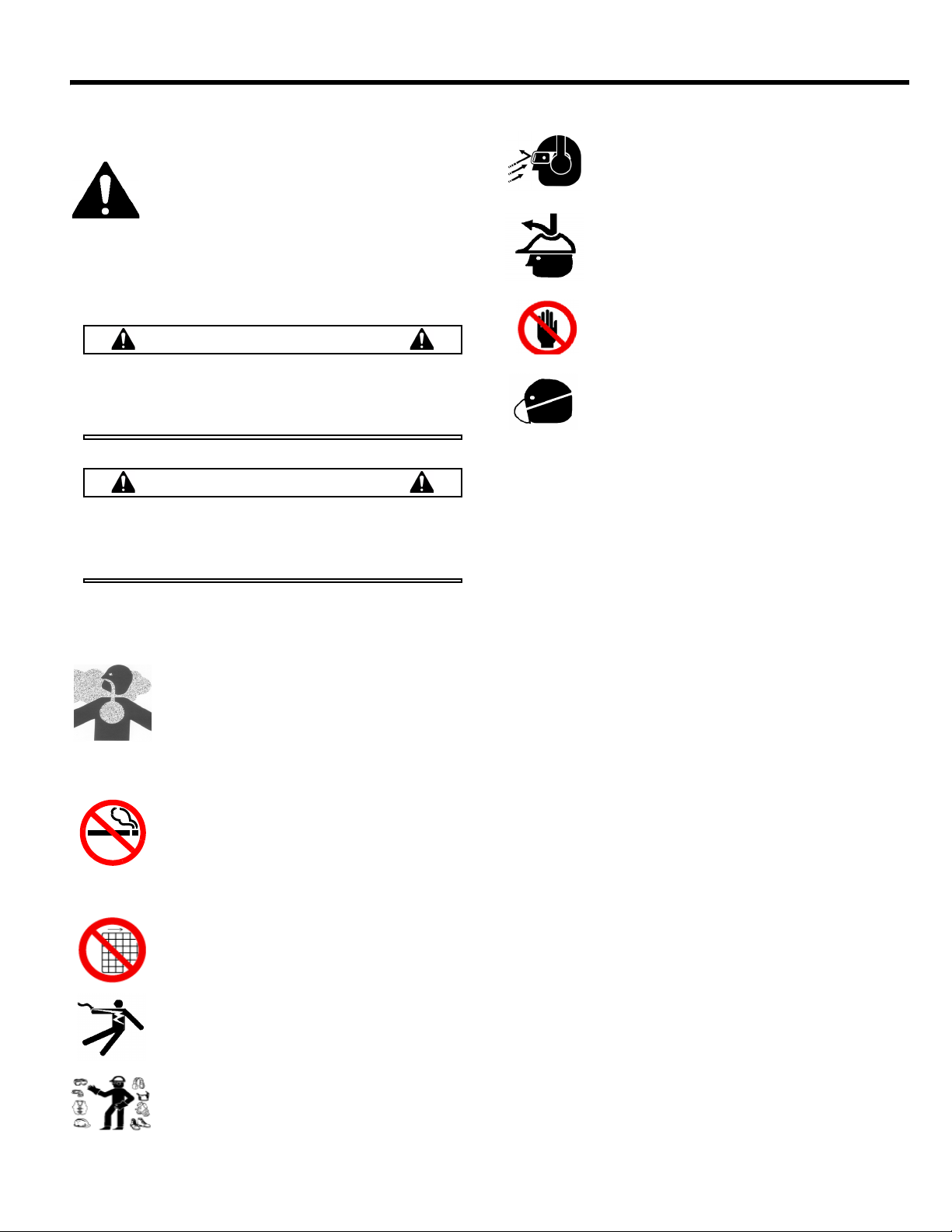
GENERAL WARNING. Indicates information
important to the proper operation of the equipment.
Failure to observe may result in damage to the
equipment and/or severe bodily injury or death.
CAUTION
GENERAL CAUTION. Indicates information
important to the proper operation of the equipment.
Failure to observe may result in damage to the
equipment.
Safety Precautions
LETHAL EXHAUST GAS: An internal
combustion engine discharges carbon
monoxide, a poisonous, odorless, invisible
gas. Death or serious illness may result if
inhaled. Operate only in a properly ventilated
area. NEVER OPERATE IN A CONFINED
AREA!
DANGEROUS FUELS: Use extreme caution
when storing, handling and using fuels as they
are highly volatile and explosive in vapor
state. Do not add fuel while engine is running.
Stop and cool the engine before adding fuel.
DO NOT SMOKE!
SAFETY GUARDS: It is the owner's
responsibility to ensure that all guards and
shields are in place and in working order.
IGNITION SYSTEMS: Breakerless, magneto,
and battery ignition systems can cause severe
electrical shocks. Avoid contacting these units
or their wiring.
SAFE DRESS: Do not wear loose clothing,
rings, wristwatches, etc. near machinery.
NOISE PROTECTION: Wear OSHA specified
hearing protection devices.
EYE PROTECTION: Wear OSHA specified
eye shields, safety glasses, and sweat bands.
FOOT PROTECTION: Wear OSHA specified
steel-tipped safety shoes.
HEAD PROTECTION: Wear OSHA specified
safety helmets.
OPERATOR: Keep children and bystanders
off and away from the equipment.
DUST PROTECTION:Machining, crushing or
handling of stone, concrete, masonry, metal
and other materials may generate dust, mist
and fumes containing chemicals such as silica
known to cause serious or fatal injury or illness such as
respiratory disease, silicosis, cancer, birth defects, or other
reproductive harm.
• Control dust, mist and fumes at the source where possible.
Water should be used to control dust whenever feasible.
• Use good work practices and follow the recommendations
of the manufacture, OSHA/NIOSH and other occupational
trade associations.
• When hazards cannot be eliminated the operator and any
bystanders should always wear a OSHA specified respirator
for materials being handled.
REFERENCES: For details on safety rules and regulations
in the United States, contact your local Occupational Safety
and Health Administration (OSHA) office. Equipment
operated in other countries must be operated and serviced
in accordance and compliance with any and all safety
requirements of that country. The publication of these safety
precautions is done for your information. MBW does not, by
the publication of these precautions, imply or in any way
represent that these are the sum of all dangers present near
MBW equipment. If you are operating MBW equipment, it is
your responsibility to insure that such operation is in full
accordance with all applicable safety requirements and
codes. All requirements of the United States Federal
Occupational Safety and Health Administration Act must be
met when operated in areas that are under the jurisdiction
of that United States Department.
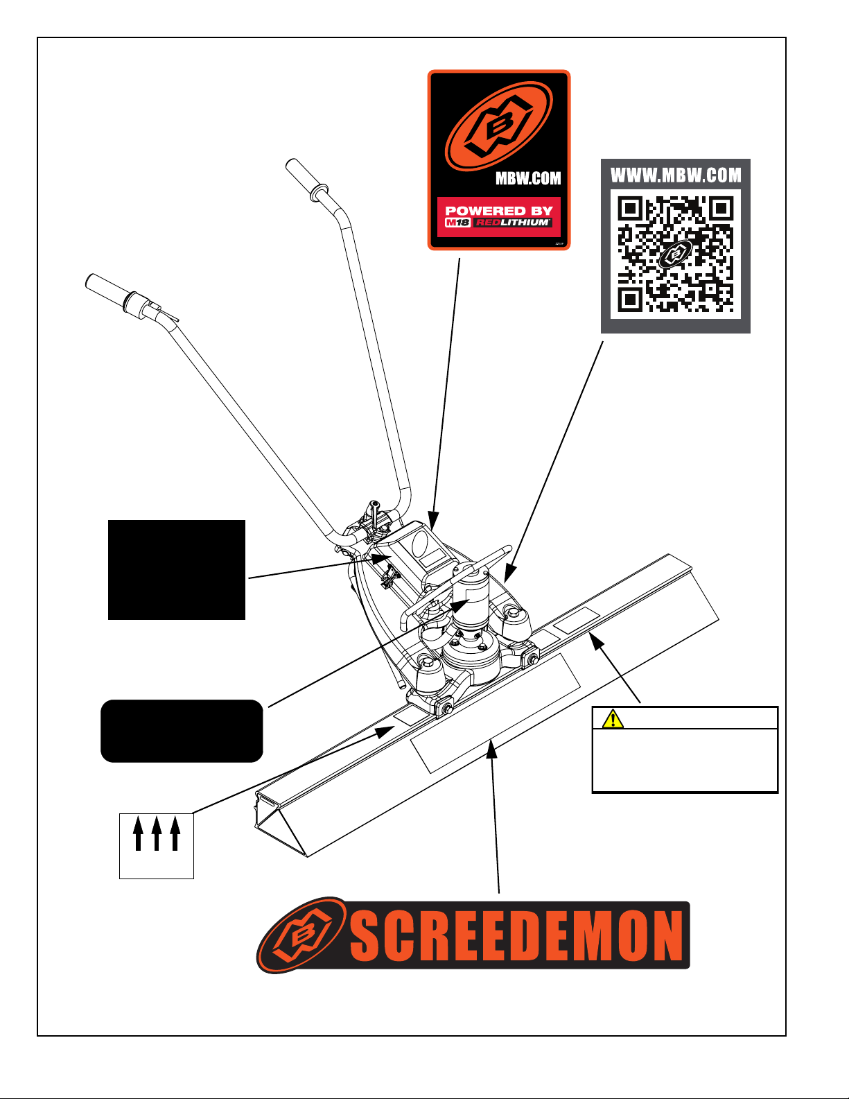
Safety Decals
Carefully read and follow all safety decals. Keep them in
good condition. If decals become damaged, replace as
required. If repainting the unit, replace all decals. Decals are
available from authorized MBW distributors. Order the decal
set listed on the following page.

- 2 -
EWS500
For best
performance use
Milwaukee Tool's
M18
REDLITHIUM
HIGH OUTPUT
batteries. 22158
21746
WARNING
Operating, servicing and maintaining this equipment
can expose you to chemicals, including engine
exhaust, phthalates and lead, which are known to the
state of California to cause cancer and birth defects or
other reproductive harm. Avoid breathing engine
exhaust. Do not operate equipment in confined areas.
For more information go to
www.P65Warnings.ca.gov
21820
EXCITER
LOCATION
Safety Decals
22159
22333
22158 (inside cover)
21746
17769
21820
17768

- 1 -
SPECIFICATIONS
Blade Specifications
Specifications subject to change without notice
500M
Operating Weight 33.5 lbs (15.2 kg) including 12 amp hr battery
Part # Width Weight
17804 4 ft (1.21 m) 8.1 lb (3.7 kg)
17806 6 ft (1.83 m) 12.1 lb (5.5 kg)
17808 8 ft (2.44 m) 16.1 lb (7.3 kg)
17810 10 ft (3.05 m) 20.1 lb (9.1 kg)
17812 12 ft (3.66 m) 24.0 lb (10.9 kg)
17814 14 ft (4.27 m) 28.0 lb (12.7 kg)
17816 16 ft (4.88 m) 32.0 lb (14.5 kg)
17818 18 ft (5.49 m) 36.0 lb (16.3 kg)
17820 20 ft (6.10 m) 40.0 lb (18.1 kg)
17824 24 ft (7.32 m) 47.9 lb (21.7 kg)

- 2 -
OPERATION
Introduction
MBW equipment is intended for use in very severe
applications. They are available in different sizes and a
selection of engines and motors.
This parts manual contains only standard parts. Variations
of these parts as well as other special parts are not included.
Contact your local MBW distributor for assistance in
identifying parts not included in this manual.
Before Starting & Operating
• REMEMBER! It is the owner’s responsibility to
communicate information on the safe use and proper
operation of this unit to the operators.
• Review ALL of the Safety Precautions listed on page 1 of
this manual.
• Familiarize yourself with the operation of the machine
and confirm that all controls function properly.
• Know how to STOP the machine in case of an
emergency.
• Make sure hands, feet, and clothing are at a safe
distance from any moving parts.
Attaching Blade
Refer to Figure 1.
1. Loosen the bolts that secure the clamps to the exciter
assembly.
2. Lay the float blade on the floor with the decals facing
upward.
3. Center the exciter between the “Exciter Location”
decals on the float blade.
4. Tilt the exciter forward and hook the small leg of the
clamping plates under the front lip of the float blade.
5. Set the exciter onto the blade so the rear part of the
exciter casting lines up with the rear cavity of the float
blade.
6. Tighten the clamping plate bolts.
Starting Screed
1. Insert battery and latch cover. Throttle must be fully
closed when battery is in inserted.
For Best performance use only Milwaukee Tool’s M18TM
REDLITHIUMTM HIGH OUTPUTTM batteries.
2. Turn throttle.
Stopping Screed
1. Move throttle to idle position.
WARNING
Always stop the motor before:
Replacing battery.
Before making any repairs or adjustments to the
machine.
Float Blade
Exciter
Clamping
Plate
Bolt
Figure 1.

- 3 -
Operation
Before placing the ScreeDemon in concrete make sure the
clamps securing the exciter to the float blade are tight.
CAUTION
Keep the blade clamps tight at all times. Operat-
ing the ScreeDemon with the clamps loose will
damage the float blade.
CAUTION
Never run the ScreeDemon above idle when the
float blade is not in contact with concrete. This
can damage the float blade.
The ScreeDemon can be used with or without forms. The
following describes the use of the ScreeDemon without
forms.
1. Use a hand float to make a 12-18” diameter wet pad
(A) at the desired grade in the four corners of the area
you wish to screed. The outer extents of the wet pads
should not exceed the length of the float blade being
used.
NOTE: Use a laser receiver, transit level, or grade
stakes to help establish the correct grade.
2. Run the ScreeDemon between the wet pads to create
two parallel strips (B) that define the grade for the
remainder of the wet screeding. These strips should
be 12-18” wide.
3. Place one end of the float blade on each of the
parallel strips (B) and screed the concrete (C) in
between the strips. Be sure the float blade follows
the contour of the parallel strips.
Blade Length
12-18"
AA
AA
Step 1.
B
B
Step 2.
B
B
C
Step 3.

- 4 -
Handle Adjustment
The operator can adjust the handle on the
ScreeDemon to a comfortable position.
Refer to Figure 2.
1. Loosen the handle by turning the handle
adjustment lever counter-clockwise.
Reorienting the lever by depressing the
center button.
2. Move the handle to the desired position.
3. Tighten the handle adjustment lever.
Kickstand
The kickstand will support the ScreeDemon in an
upright position when not in use.
Transporting
It is recommended to transport the ScreeDemon with the
float bar removed. The float bar is more likely to be
damaged if attached to the main unit during transport.
The handle can be collapsed for easier transport. See
Figure 3.
Figure 2.
+$1'/(
$'-8670(17
/(9(5
.,&.67$1'
Figure 3.

- 5 -
MAINTENANCE
WARNING
Always exercise the stopping procedure and
remove battery before servicing or lubricating the
unit.
After servicing the unit, replace and fasten all
guards, shields, and covers to their original
positions before resuming operation.
CAUTION
Always verify fluid levels and check for leaks after
changing fluids.
Do not drain oil onto ground, into open streams,
or down sewage drains.
Maintenance Schedule
1. Check all hardware after the first 5 hours of use, then follow the maintenance schedule.
2. Service kit pn 20192
Motor Maintenance
The electric motor is a sealed unit and no periodic
maintenance is required.
Battery Maintenance
For battery care, maintenance, and charging information
refer to Milwaukee Tool Technical documentation included
with battery.
Cleaning
Clean any concrete from the ScreeDemon immediately
after each use. DO NOT allow concrete to harden on
the screed.
1. Remove battery.
2. Use a hose to remove any excess concrete. Avoid
spraying water into battery compartment.
3. Remove any buildup with hard plastic bristle brush.
NOTE: DO NOT use a wire brush, hammer, or pressure
washer to remove concrete from the main unit or
float blade.
4. Remove the blade.
5. Insert battery, Start motor and run the exciter for
about 10 seconds.
6. Remove battery.
Checking and Replacing Shock Mounts
For the best reliability, replacing the shock mounts
once per year is recommended.
For instructions on replacing shockmounts, refer to ‘Motor
Removal’ and ‘Exciter disassembly, page 6.
SYSTEM MAINTENANCE EACH USE EVERY 20
HOURS
EVERY 100
HOURS YEARLY
Hardware Check and tighten as needed1XX
Shock mounts Check for cracks or tears X
Shock mounts Replace X

- 6 -
SERVICE
Assembly and disassembly should be performed by a
service technician who has been factory trained on MBW
equipment. The unit should be clean and free of debris.
Washing before disassembly is recommended.
• Prior to assembly, wash all parts in a suitable cleaner or
solvent.
• Check moving parts for wear and failure. Refer to the
Replacement Parts section in this manual for tolerance
and replacement cycles.
• All shafts and housings should be oiled prior to pressing
bearings. Also, ensure that the bearings are pressed
square and are seated properly.
• All bearings should be replaced when rebuilding any
exciter or gearbox.
• All gaskets and seals should be replaced after any
disassembly.
Torque Chart
Motor Removal
Refer to Motor Assembly, page 24.
1. Remove battery.
2. Remove bottom cover (#5,page 20) from
ScreeDemon to access wiring compartment
3. Identify and detach motor wiring (terminals 1 and 2)
by inserting a small screwdriver in terminal strip hole
above wire to be disconnected, and levering
screwdriver to release wire clamp.
4. Loosen two pinch bolts (#8) securing motor adapter
(#4) to exciter assembly (#5) and remove motor.
Take care to not lose woodruff key (#1).
5. Pull hose (#3) off of motor adapter (#4) and pull wiring
through.
6. Motor (#2) can be removed from adapter (#4) by
removing the nuts (#6).
Exciter Disassembly
Refer to Exciter Assembly, page 16.
1. Remove battery.
2. Loosen two pinch bolts securing motor adapter to
exciter assembly, and pull motor assembly off. Take
care not to lose woodruff key.
3. With screed bar removed, flip machine upside down
and remove three bolts securing shockmounts.
Exciter assembly is now disconnected from the
machine.
4. Remove the plug (#2) from the flange.
5. Use an 1/8” allen wrench to loosen the set screw
(#18) inside the exciter housing, directly below the
hole.
6. Stick a rod of screwdriver straight down through both
holes to prevent rotation of exciter.
7. Remove the three hex head cap screws (#19) and
sealing washers (#5) from the mounting flange.
8. Rotate the drive shaft (#13) counter clockwise with a
screwdriver in the key way to remove the drive shaft
and remove cover (#12).
9. Unthread the three shockmounts (#7) from the exciter
housing (#4). Unthread the center shockmount from
the exciter (#14) using a rod to prevent the rotation of
the exciter as in step 8.
10. Loosen the three socket head cap screws (#20)
securing the cover (#8). Back the screws off about a
1/4”
SIZE GRADE 2 GRADE 5 GRADE 8
1/4-20 49 in•lbs 76 in•lbs 9 ft•lbs
1/4-28 56 in•lbs 87 in•lbs 10 ft•lbs
5/16-18 8 ft•lbs 13 ft•lbs 18 ft•lbs
5/16-24 9 ft•lbs 14 ft•lbs 20 ft•lbs
3/8-16 15 ft•lbs 23 ft•lbs 33 ft•lbs
3/8-24 17 ft•lbs 26 ft•lbs 37 ft•lbs
7/16-14 24 ft•lbs 37 ft•lbs 52 ft•lbs
7/16-20 27 ft•lbs 41 ft•lbs 58 ft•lbs
1/2-13 37 ft•lbs 57 ft•lbs 80 ft•lbs
1/2-20 41 ft•lbs 64 ft•lbs 90 ft•lbs
9/16-12 53 ft•lbs 82 ft•lbs 115 ft•lbs
5/8-11 73 ft•lbs 112 ft•lbs 159 ft•lbs
5/8-18 83 ft•lbs 112 ft•lbs 180 ft•lbs
3/4-16 144 ft•lbs 200 ft•lbs 315 ft•lbs
1-8 188 ft•lbs 483 ft•lbs 682 ft•lbs
1-14 210 ft•lbs 541 ft•lbs 764 ft•lbs
1-1/2-6 652 ft•lbs 1462 ft•lbs 2371 ft•lbs
M 6 3 ft•lbs 4 ft•lbs 7 ft•lbs
M 8 6 ft•lbs 10 ft•lbs 18 ft•lbs
M 10 10 ft•lbs 20 ft•lbs 30 ft•lbs
CONVERSIONS
in•lbs x 0.083 = ft•lbs
ft•lbs x 12 = in•lbs
ft•lbs x 0.1383 = kg•m
ft•lbs x 1.3558 = N•m

- 7 -
11. Gently tap on the socket head screws with a rubber
mallet to push the exciter cover out of the exciter
housing, then finish removing screws.
12. Remove the bearings (#6) from the exciter housing,
exciter cover, and eccentric shaft.
Exciter Assembly
Refer to Exciter Assembly, page 16.
1. Press a bearing (#6) into the exciter housing (#4) and
exciter cover (#8).
2. Turn the exciter housing upside down and place the
threaded end of the eccentric weight (#14) into the
bearing in the housing.
3. Apply a light coat of grease to the step of the cover
(#8) and new o-ring (#1).
4. Apply a medium strength thread lock to the threaded
holes in the cover.
5. Line up the mounting holes between the exciter
housing and exciter cover and assemble. Take care
not to cut the o-ring. Secure the cover with three
screws (#20) and fiber washers (#11)
6. Thread the shockmounts (#7) into the housing.
7. Apply medium strength locker to threads of center
shockmount and thread into eccentric.
8. Inspect the rubber seal on mount (#12). Replace if
there are any tears or wear. If the seal is in good
condition, skip to step 12.
9. Clean the surfaces of the mounting flange where the
rubber seal was glued.
10. Apply a small bead of Loctite 426 adhesive (MBW
#17885) to the lip on the engine mounting flange as
shown below.
11. Place a new rubber seal onto the mounting flange
and hold it for 10 seconds to allow the adhesive to
set.
12. Apply medium strength locker to the threads on the
end of the drive shaft (#13).
13. Position the mounting flange on the exciter assembly
so that the plug hole aligns with the set screw on the
exciter (#18).
14. Set the mounting flange in place while turning the
drive shaft clockwise to tighten into the center
shockmount.
15. Secure the flange in place with three sealing washers
(#5) and screws (#19).
16. Apply medium strength locker to the set screw (#18)
and install into exciter housing.
17. Replace the plug (#2).
Motor Installation
Refer to Motor Assembly, page 24.
1. Apply a light coating of grease to the ID of motor
adapter (#4) and slide it onto exciter assembly (#5).
2. Connect hose (#3) between electrical compartment
and motor adapter.
3. Install woodruff key (#1) into shaft of motor. Use of
super glue may help retain key if needed to keep in
place during assembly.
4. Apply a light coating of grease to motor shaft and
install onto adapter. Take care to ensure the woodruff
key remains in place and that the wiring is routed into
electrical compartment.
5. Secure motor to motor adapter with washers (#7) and
nuts (#6). Use a medium strength thread locker on
the nuts.
6. Position motor adapter (#4) such that hose (#3) does
not rub on exciter assembly.
7. Tighten motor adapter onto shaft with pinch bolts
(#8). Use medium strength thread locker.
8. Connect motor wiring as shown on Electrical
Assembly, page 20.
Motor Adapter Bearing Replacement
Refer to Motor Mount, page 18.
1. Follow directions 1-8 in “Exciter Disassembly”
2. Press bearing (#2) out of adapter (#1)
3. Apply light coating of Loctite 603 bearing retainer to
OD of new bearing and press into place.
4. Drive shaft should slip into place.
5. Follow “Exciter Assembly” instruction steps 12-17
APPLY
ADHESIVE
HERE

- 8 -
TROUBLESHOOTING
If your Electric ScreeDemon fails to operate as expected,
the first test will always be to confirm a genuine Milwaukee
battery is fully installed and charged. Removing and
reinstalling the battery will reinitialize the throttle control
board, clearing any faults that were detected during
operation.
Battery Interface
The purpose of the battery interface is to supply 18 volts to
the throttle control board. Typically the battery interface is
known to be in good condition if the LED lights come on
when a battery is inserted. To further trouble shoot the
battery interface, follow the steps below.
Refer to Electrical Assembly, page 20.
1. Remove bottom cover (#5) over the throttle control
board.
2. Identify wires at terminals 3 and 4. These are the
wires which supply power to the board.
3. Insert a known-good battery.
4. Measured voltage between terminals 3 and 4 should
be 18 volts, within 3 volts.
5. If voltage levels are not as described, replace battery
interface.
Electronic Throttle
The purpose of the electronic throttle is to provide a signal
to the throttle control board. The throttle contains a 0-5k
ohm potentiometer to supply this signal. To verify function of
the electronic throttle, complete the following steps.
1. Remove battery from machine.
2. Remove bottom cover from electrical enclosure.
3. Identify, and remove black, brown, and blue wires
from terminals 6,7, and 8, Respectively. To remove
wires, press small button above terminal with small
screwdriver while gently pulling on wires.
4. The measured resistance between the blue and
black wires should be 5k ohms, within 500 ohms.
5. The measured resistance between the black and
brown wires should be under 20 ohms and increase
smoothly to over 4.5k ohms as the throttle is turned.
6. If resistance measured isn’t as described, replace
electronic throttle.
7. When reinserting the wires, be very cautious that all
of the conductors remain contained in the terminal.
18v Motor
The motor utilized by the MBW ScreeDemon is a permanent
magnet, brushed dc motor. It is a permanently sealed and
water tight motor designed to last the life of the machine and
survive wash down with a low pressure hose. To verify that
motor is performing to specifications, follow the steps below.
1. Loosen pinch bolts securing the motor in place and
remove the motor from the exciter assembly. Take
care to not lose the woodruff key.
2. Motor shaft should spin freely without binding. If shaft
does not spin freely, replace motor.
3. Insert a battery and turn throttle. Motor shaft should
spin counter clockwise while viewing the shaft end.
4. If motor does not spin, verify power is being supplied
to it appropriately by the following steps.
5. Remove the bottom over the electronics
compartment.
6. Probe wires in locations 1 and 2. While applying
throttle, voltage should increase from 0 to 18 volts.
7. If proper voltage as described above and motor does
not spin, replace motor.
Throttle Control Circuit Board
The MBW ScreeDemon uses an integrated circuit to control
the power flow between the battery interface and the motor.
This circuit board also controls the LED lights, and provides
over-current protection for the motor. If over-current
protection circuitry is tripped, the LED lights will blink several
times before the board resets. To verify performance of the
throttle control board, follow the steps below.
1. LED lights should illuminate for approximately 30
seconds after a battery is installed, while the motor is
running, and approximately 30 seconds after the
motor stops running. A short dip in the brightness of
lights during these periods might be observed and it
is normal.
2. If over-current conditions persistently occur, confirm
that the eccentric weight freely rotates, no
shockmounts are torn or worn, and remove any
excessive concrete buildup.
3. If ScreeDemon does not operate, and tests for the
battery interface, electronic throttle, and motor do not
show faults, replace throttle circuit board.

- 9 -
Parts Replacement Cycles and Tolerances
Bearings Replace anytime a bearing is rough, binding, discolored or removed from housing or
shaft.
Hardware Replace any worn or damaged hardware as needed. Replacement hardware should
be grade 5 and zinc plated unless otherwise specified.
Safety Decals Replace if they become damaged or illegible.
Seals & Gaskets Replace if a leak is detected and at every overhaul or teardown.

- 10 -
This page intentionally left blank.

- 11 -
MBW, Inc.
250 Hartford Rd • PO Box 440
Slinger, WI 53086-0440
Phone: (262) 644-5234
Fax: (262) 644-5169
Email: mbw@mbw.com
Website: www.mbw.com
MBW Europe Ltd.
Units 2&3 CochraneStreet
Bolton BL3 6BN
England, UK
Phone: 44 (0) 01204 387784
Fax: 44 (0) 01204 387797
Contact Information
REPLACEMENT PARTS
The warranty is stated in this book on page 26. Failure to
return the Warranty Registration Card renders the warranty
null and void.
MBW has established a network of reputable distributors/
dealers with trained mechanics and full facilities for
maintenance and rebuilding, and to carry an adequate parts
stock in all areas of the country. Their sales engineers are
available for professional consultation. If you cannot locate
an MBW distributor in your area, contact MBW or one of our
Sales Branches listed below.
When ordering replacement parts, be sure to have the
following information available:
• Model and Serial Number of machine when ordering
MBW parts
• Part Number, Description, and Quantity
• Company Name, Address, Zip Code, and Purchase
Order Number
• Preferred method of shipping
REMEMBER - You own the best! If repairs are needed,
use only MBW parts purchased from authorized
MBW distributors.
The unit’s serial number can be found in the following
locations:
• Decal inside battery compartment
Write Model Number here
Write Serial Number here
DECAL

- 12 -
Main Assembly

- 13 -
ITEM PART NO. DESCRIPTION QTY
1. 17170 SHOCKMOUNT, 2” OD X 1-3/4 LONG 3
2. 22408 HANDLE, 500M, MASKED 1
3. 21181 HANDLE, ADJUSTABLE, NYLON 1
4. 22112 PUSH NUT 2
5. 22117 HANDLE, LIFTING 1
6. 22119 HANDLE CLAMP, MACHINED 1
7. 21781 5/16 X 2-1/2 STUD 1
8. 22125 HINGE PIN 1
9. 22126 WRENCH, 9/16 1
10. 22135 COVER ASM 1
11. 22138 BATTERY CONNECTOR ASM 1
12. 22143 THROTTLE, ELECTRONIC (includes both grips) 1
13. 22271 EXCITER, SCREED, M18 1
14. 22150 AFRAME, SUB ASM 1
15. F0132HN NUT, HEX #6-32 ZP 2
16. F032403HCS HHCS, #10-24 X 3/8 GR5 ZP 10
17. F051808FWS FWLS, 5/16-18 X 1 ZP 2
18. F051812FWS FWLS, 5/16-18 X 1-1/2 ZP 1
19. F081305HCS HHCS, 1/2-13 X 5/8 GR5 ZP 3
20. M12ETLW LOCKWASHER, M12, EXT TOOTH 3

- 14 -
Cover Assembly

- 15 -
ITEM PART NO. DESCRIPTION QTY
1. 22136 DRAW LATCH 1
2. 22135 COVER ASM (INCLUDES ALL PARTS SHOWN) 1
3. F02LW WASHER 3/16 X 7/16 X 18 GA 2
4. F0232HN NUT, HEX #8-32 UNC 2
5. F023204PMS PMS #8-32 UNC X 1/2 2
This manual suits for next models
1
Table of contents
Popular Construction Equipment manuals by other brands

Peri
Peri Trio Instructions for assembly and use

MDB
MDB Green Climber LV800 Operation and maintenance manual

stellar labs
stellar labs 6000 owner's manual

ELEM Technic
ELEM Technic DPP2200 user manual

stellar labs
stellar labs STUD KING MD25 owner's manual

Vestil
Vestil WTJ-HITCH Series Use and maintenance manual

HADEF
HADEF 320/01 Installation, Operating and Maintenance Instructions for the Installer and the User

Vestil
Vestil CBFC Operation and maintenance manual

MQ
MQ Mikasa MT55F Operation manual

Atlas Copco
Atlas Copco Dynapac CP274 instruction manual

nvent
nvent RAYCHEM HWAT-SYSTEM Installation and maintenance manual

SANY
SANY SCC 2600A manual