SKB Primo 27 AD User manual

Instruction manual and assembly
instructions, test log and installation
documentation in accordance with
DIN EN 795:2012 lass A
Primo 27 AD
This instruction manual, including a test log, must be read before first use and kept with the equipment for
its entire service life. nly persons who are familiar with this instruction manual may use the system.

Sicherheitskonzepte Breuer GmbH Broekhuysener Straße 40, 47638 Straelen, Tel.: +49 2834 943 01 00, Fax: +49 2834 943 05 62
info@sicherheitskonzepte-breuer.com, www.sicherheitskonzepte-breuer.com
2
Instruction manual for anchor device in accordance with
DIN EN 795:2012 Class A
Type: Primo
The anchor devices, type: PRIM are used as anchor points in fall-arrest systems for personal protective equipment against falls from a
height or for use with restraint systems, and are designed to be assembled on various surfaces.
Assuming correct assembly and proper use, the anchor device (used with a suitable fall-arrest or restraint system) prevents the user from
hitting the ground or from other obstacles.
The anchor devices, type: PRIM are tested in accordance with DIN EN 795:2012.
The anchor devices may only be used in the prescribed operating conditions, and not as, e.g., transport lugs or for attaching loads.
Health impediments (e.g. heart/circulatory problems, or alcohol/medication intake) can affect the safety of the user when working at height.
The equipment may only be used by trained individuals who are confident in handling it.
A plan must be in place that covers rescue operations in all potential emergency situations.
No changes or additions may be made to the equipment without the prior written consent of the manufacturer. All maintenance may only
be performed in accordance with the measures specified by the manufacturer.
Combining individual elements of this equipment can cause hazards, which can impair the safe function of the system. Therefore please
ensure that the constituent parts of this system are compatible with each other.
The anchor device is designed for bearing loads in all directions parallel to the masonry.
The maximum force, which can be exerted in practice from the anchor device into the structural element, is:
when used by one person = 6 kN
when used by two persons = 7 kN
when used by three persons = 8 kN
The user must inspect the equipment before use to ensure that it is in a usable condition and is functioning properly.
aution:
For safety reasons, the anchor device must be withdrawn from use if
1. there are any doubts about its safe use (e.g., identification of damage (cracks or breakages)) or
2. the equipment has been subjected to a fall.
In this case, the use of the equipment may only be resumed with the written approval of a qualified person.
Hazards can arise that can impair the function of the equipment.
E.g.:
Chemical influence
Electrical influence
Deformations
Abrasion
In this case, the equipment must not be used!

Sicherheitskonzepte Breuer GmbH Broekhuysener Straße 40, 47638 Straelen, Tel.: +49 2834 943 01 00, Fax: +49 2834 943 05 62
info@sicherheitskonzepte-breuer.com, www.sicherheitskonzepte-breuer.com
3
This instruction manual is supplied with every Primo anchor device. It must be read before use and stored in close proximity to the
equipment at all times.
The assembly of the anchor device is described in a separate manual.
aution: nly original parts may be used!
Please check the roof construction before assembly, i.e., always check whether the surface is suitable for attaching the anchor device. If in
doubt, contact a structural engineer.
The Primo anchor device may only be used with safety harnesses in accordance with DIN EN 361, energy absorbers in accordance with DIN
EN 355 and lanyards in accordance with DIN EN 354 for fall protection, according to the instruction manual of the respective manufacturer.
The lanyard should be equipped with a length adjustment in accordance with DIN EN 354. The opening of the carabiner hook must exceed
16 mm.
It is essential for safety that following a fall or when damage (cracks or breakages) are found, the product is only used again after obtaining
the written consent of an expert.
The information in the corresponding instruction manual must be observed.
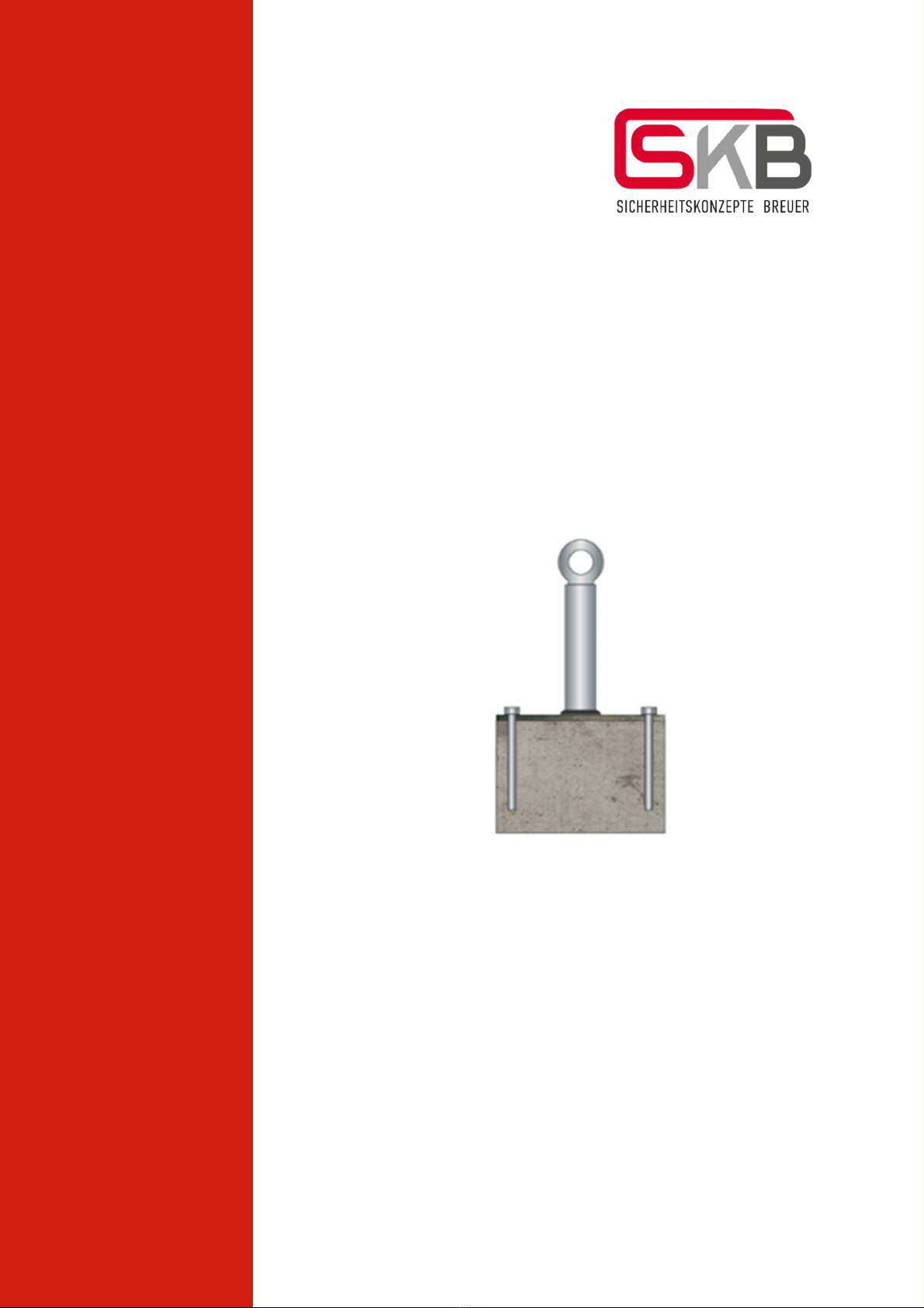
Load capacity
max. three persons per anchor point (Primo)
Before each use of the Primo
A visual and functional inspection must be conducted for the following points:
Corrosion
Deformation
Damage (e.g. distortion or cracks)
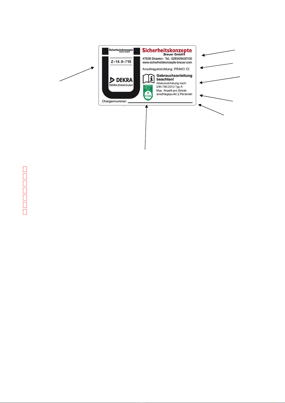
Label (nameplate) present
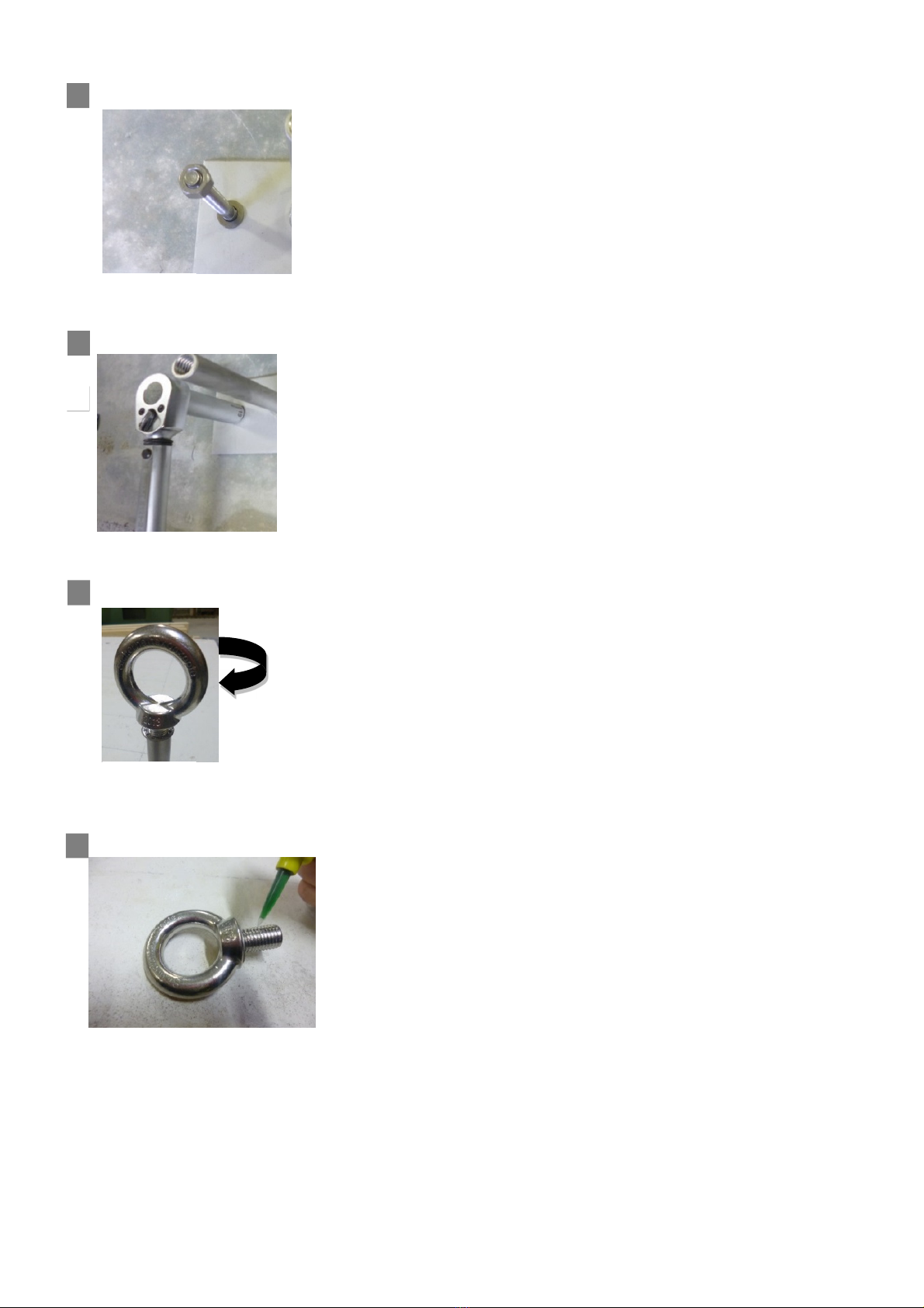
Wobble test (perform manually at the anchor point)
Ring bolt secure (screwed all the way in, firm position of the ring bolt)
Check legibility
Application:
Before entering areas where there is a risk of falling (e.g. walking on the flat roof):
Always check whether the components of the personal protective equipment against falling from a height are in order and whether they
comply with that specified in this instruction manual and/or on the inspection card.
System components must be checked for completeness and correctness.
The other personal protective equipment against falling from a height must be checked for external signs of damage and for completeness
before use, in accordance with the associated instruction manuals.
After entering areas where there is a risk of falling (e.g. walking on the flat roof):
The Primo anchor device can be used as a single anchor point, i.e., the person to be protected hooks the carabiner hook of his/her personal
protective equipment against falling from a height directly into the eyelet of the anchor point. In this case, no more than 3 persons may be
secured per eyelet.
aution: Unlocked carabiner hooks can inadvertently release from the anchor point!

Sicherheitskonzepte Breuer GmbH Broekhuysener Straße 40, 47638 Straelen, Tel.: +49 2834 943 01 00, Fax: +49 2834 943 05 62
info@sicherheitskonzepte-breuer.com, www.sicherheitskonzepte-breuer.com
4
When using the Primo anchor device, the necessary clearance height below the user must be checked and guaranteed in advance. In
addition, care must be taken to minimise free fall in the event of a fall. The necessary clearance height depends on the fall-arrest system
components used (safety harness and lanyard), its maximum extension and the displacement of the anchor point, which corresponds to
the prop height. The measurement is also determined based on the extension of the energy absorber used, as well as the displacement
of the safety harness on the body (check PPE instruction manual), the height of the user and an additional one metre of safety
clearance.
The permitted strain caused by building edges and the maximum usage length when using a restraint system must also be observed.
leaning:
Metal components must be cleaned by wiping with a cloth after use. ther cleaning methods (chemical cleaning, etc.) are not permitted.
Repairs and inspections:
Repairs to the anchor device may only be performed by the manufacturer or an expert supplier.
The Primo anchor device must be inspected as required, however at least 1x annually, by the manufacturer or an authorised expert trained
by the manufacturer, in full compliance with the manufacturer’s instructions. In any case, the product label must be checked, and the
findings of the inspection must be entered in the enclosed test log.
This is essential because the efficacy and durability of the equipment and thus the safety of the user depends on it.
In the event of resale to other countries, please ensure that this instruction manual is available to the user in the language of the respective
country.

Sicherheitskonzepte Breuer GmbH Broekhuysener Straße 40, 47638 Straelen, Tel.: +49 2834 943 01 00, Fax: +49 2834 943 05 62
info@sicherheitskonzepte-breuer.com, www.sicherheitskonzepte-breuer.com
5
4
7
5
6
Meaning of the markings
1. Product designation and type designation
2. Manufacturer
3. Standard
4. Number of users
5. Batch number
6. Year of manufacture
7. Symbol to indicate that the instruction manual must be observed
Manufacturer Notified body involved in the type examination
Sicherheitskonzepte Breuer GmbH DEKRA EXAM GmbH
Broekhuysener Straße 40 Dinnendahlstr. 9
47638 Straelen 44809 Bochum
3
2
1

Sicherheitskonzepte Breuer GmbH Broekhuysener Straße 40, 47638 Straelen, Tel.: +49 2834 943 01 00, Fax: +49 2834 943 05 62
info@sicherheitskonzepte-breuer.com, www.sicherheitskonzepte-breuer.com
6
Maintenance log
Inspection at least once a year, to be organised by the builder.
Manufacturer:
Sicherheitskonzepte Breuer GmbH
Broekhuysener Straße 40
47638 Straelen
Type designation:
Primo 27 AD
Year of manufacture:
Standard:
DIN EN 795:2012 Class A
Date of purchase:
Serial number:
Date of first use:
perator:
Date
Reason for revision (periodic inspection
or maintenance)
Damage found, repairs performed, etc.
Name/signature of
competent person
Date of the next
periodic inspection

Sicherheitskonzepte Breuer GmbH Broekhuysener Straße 40, 47638 Straelen, Tel.: +49 2834 943 01 00, Fax: +49 2834 943 05 62
info@sicherheitskonzepte-breuer.com, www.sicherheitskonzepte-breuer.com
7
Installation guide
Primo 27 AD
Anchor device for attaching personal protective equipment against falling from a height.
Surface: min. concrete C 20 / 25
Min. installation thickness 100 mm
Edge distance: 650 mm to the concrete edge
(not to building edge)
Tool: Hammer drill with drill bit Ø 10 mm
Torque spanner M 17
Fixing element: Fischer anchor bolt FAZ II 10/10 A4
Assembly preparation
Before installing the Primo 27 AD, the load capacity of the roof construction must be checked.
The technical specifications must be adhered to. The General Type Approval must be observed in planning and assembly.
The maximum force, which can be exerted in practice from the anchor device into the structural element, is:
when used by one person = 6 kN
when used by two persons = 7 kN
when used by three persons = 8 kN
Assembly distances for flat roof
min. 2.5 m
max. 7.5 m
max. 7.5 m
min.
2.5 m
up to 700 mm, assemble without roof construction
from 700 mm, assemble only with roof construction

Sicherheitskonzepte Breuer GmbH Broekhuysener Straße 40, 47638 Straelen, Tel.: +49 2834 943 01 00, Fax: +49 2834 943 05 62
info@sicherheitskonzepte-breuer.com, www.sicherheitskonzepte-breuer.com
8
Assembly steps
1
To mark the four boreholes, place the base plate on the concrete slab with an edge distance of 650 mm to the concrete edge (not to
building edge)
Figure 1
2
Bore the four ø 10 mm boreholes perpendicular to the concrete surface 85 mm deep in the concrete.
Figure 2
3
Remove the generated dust from the concrete slab (e.g. with hand brush).
Figure 3
4. Blow-out the boreholes 2 times.
Figure 4
Installation
variant
650
650

Sicherheitskonzepte Breuer GmbH Broekhuysener Straße 40, 47638 Straelen, Tel.: +49 2834 943 01 00, Fax: +49 2834 943 05 62
info@sicherheitskonzepte-breuer.com, www.sicherheitskonzepte-breuer.com
9
5 Place Primo 27 AD on the concrete slab and insert all four heavy-duty anchors of the anchor device and hammer in.
6 Screw-in the heavy-duty anchor clockwise using a torque spanner and tighten with 45 Nm.
7 Position the eyelet and screw-in clockwise. Tighten until the ring bolt cannot be manually released.
8 nly with single anchor point! To secure the eyelet, apply adhesive to the ring bolt with high-strength screw lock (e.g. Loctite).
Figure 5
Figure 6
Figure 7
Figure 8

Sicherheitskonzepte Breuer GmbH Broekhuysener Straße 40, 47638 Straelen, Tel.: +49 2834 943 01 00, Fax: +49 2834 943 05 62
info@sicherheitskonzepte-breuer.com, www.sicherheitskonzepte-breuer.com
10
ontracting authority
Building section
Installation documentation: Fall Protection
Type: Primo 27 AD
Address rder no.
Post code / Place Building type
Supplement Roof shape
Address Contact person
Post code / Place Telephone
Address Assembler
Post code / Place Email
Telephone Extension
Component 1 expected component thickness
Component 2 expected component thickness
Material
Setting data: □ Bore Ø: 10 mm
□
Minimum component thickness: Concrete min. 100 mm
□
Bore depth: 85 mm
□
Torque: 45 Nm
□ Hammer drill
□ Boreholes cleaned 2x
□ Tightened with 45 Nm
□ Drill bit Ø 10 mm
Assembly
company
Building
Borehole create with:
Fixing
Bolt anchor FAZ
II 10/10
Manufacturer
Fischer
Setting data

Sicherheitskonzepte Breuer GmbH Broekhuysener Straße 40, 47638 Straelen, Tel.: +49 2834 943 01 00, Fax: +49 2834 943 05 62
info@sicherheitskonzepte-breuer.com, www.sicherheitskonzepte-breuer.com
11
□ Surface as expected
□ Fixings specifications satisfied
□ Manufacturer specifications fulfilled
□ Nameplate present
□ Screw lock used
□ No extra concrete
□ Building Type Approval Z-14.9-710 taken into account
Anchor point: Nm: Anchor point: Nm: Anchor point: Nm: Anchor point: Nm: Anchor point: Nm:
1 10 19 28 37
2 11 20 29 38
3 12 21 30 39
4 13 22 31 40
5 14 23 32 41
6 15 24 33 42
7 16 25 34
8 17 26 35
9 18 27 36
Remarks
Date Assembly Company Signature Assembler
Manufacturer
Breuer Sicherheitskonzepte GmbH
Broekhuysener Straße 40
47638 Straelen
Applied torque reached
Rough sketch, roof plan (see attachment)
Photo documentation (see
attachment)
Roof plan

Instruction manual and assembly instructions, log book
and installation documentation in accordance with DIN EN 795:2012 Class A
Primo 27 AD
Sicherheitskonzepte Breuer GmbH
Broekhuysener Straße 40
47638 Straelen
Tel.: +49 (0) 2834 943 01 00
Fax: +49 (0) 2834 943 05 62
info@sicherheitskonzepte-breuer.com
www.sicherheitskonzepte
-
breuer.co
m
Table of contents