MBM FC 10 PLUS User manual

- 0 -
SERVICE MANUAL
MBM TABLETOP COLLATOR
MODEL FC 10 PLUS
R e v 1 . 0 㻌
㻌㻌㻌
Sep.09.2016

1
CONTENTS
1. Components................................................................................................................................... 4
1.1 Overview......................................................................................................................... 4
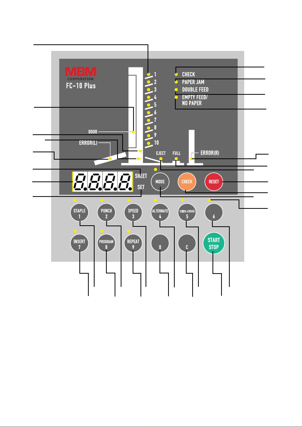
1.2 Operation Panel............................................................................................................... 6
2. Precaution for Maintenance and Inspection.................................................................................. 8
2.1 Usual maintenance.......................................................................................................... 8
2.1.1 Clean-up paper feed roller, separator and Paper Ejection sheet photo sensor .......... 8
2.1.2 Cleaning of Paper Ejection sheet photo sensor.................................................. 10
3. Preparation for use................................................................................................................... 11
3.1 Installing attachments.................................................................................................. 11
3.1.1 Mount the plate to prevent the machine from falling......................................... 11
3.1.2 Power connection............................................................................................... 11
3.1.3 Stacking table assembly...................................................................................... 12
3.1.4 Stacking table..................................................................................................... 12
3.1.5 Switch Single/Option.......................................................................................... 13
3.1.6 Display of total count of sheets.......................................................................... 14
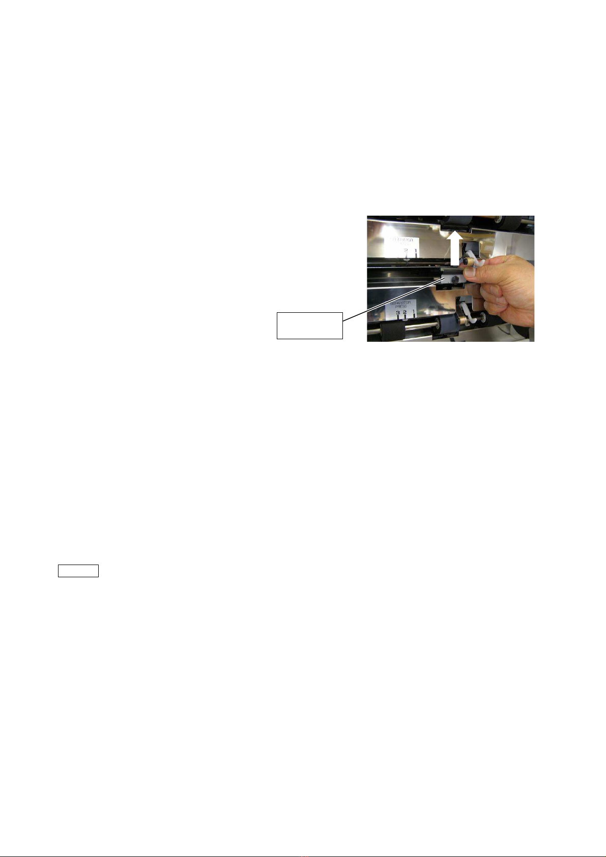
3.1.7 Setting paper feed pressure................................................................................. 14
3.1.8 Setting separator pressure................................................................................... 14
4. Setting Paper.............................................................................................................................. 15
4.1 Precautons for setting paper......................................................................................... 15
4.2 Order of loading paper................................................................................................. 16
4.3 Loading paper in Alternate mode................................................................................. 16
4.4 Loading paper in Insert and Program mode................................................................. 17
5. Response to Light and Flashing of Lamps (ERROR MESSAGE)............................................ 18
6. Main printed circuit board.......................................................................................................... 20
7. Wiring Diagram.......................................................................................................................... 21
8. Paper detection wire angle adjustment procedures.................................................................... 22
9. How to replacement of Parts..................................................................................................... 23
9.1 Operation panel side..................................................................................................... 23
9.1.1 Power switch....................................................................................................... 23
9.1.2 Long distance transmission sensor (Receiving)................................................. 25
9.1.3 Paper Ejection sheet switching micro switch..................................................... 25
9.1.4 Paper detection micro switch.............................................................................. 25
9.1.5 Door open detection micro switch...................................................................... 26

2
9.2 Back door..................................................................................................................... 27
9.2.1 Dismounting procedures of the back door.......................................................... 27
9.2.2 Remove flat belt.................................................................................................. 28
9.3 Anti-operation side....................................................................................................... 30
9.3.1 Optical sensor for encoder.................................................................................. 30
9.3.2 Paper feed clutch................................................................................................ 30
9.3.3 Timing belt......................................................................................................... 33
9.3.4 Breaker............................................................................................................... 35
9.3.5 Long distance transmission sensor (send).......................................................... 35
9.3.6 Lift motor............................................................................................................ 36
9.3.7 Main motor......................................................................................................... 37
9.4 Body case .................................................................................................................... 41
9.4.1 Shift motor.......................................................................................................... 41
9.4.2 Micro switch for Shift motor.............................................................................. 43
9.4.3 Switching power supply..................................................................................... 43
9.4.4 Paper ejection roller (upper)............................................................................... 45
9.4.5 Paper ejection roller (lower)............................................................................... 46
9.5 Paper feed unit......................................................................................................... 47
9.5.1 Receiving board/ Emission board....................................................................... 47
9.5.2 Paper detection wire........................................................................................... 52
9.5.3 Feed roller........................................................................................................... 54
9.5.4 Separator............................................................................................................. 54
10. Diagram for Belt Installation...................................................................................................... 55
11. Test Mode................................................................................................................................... 56
11.1 How to set test mode............................................................................................... 56
11.2 Test mode functions................................................................................................ 56
11.3 Checking the operation............................................................................................ 57
11.4 Check on sensor function........................................................................................ 58
11.5 Photo sensor check mode........................................................................................ 58
12. Changing the system parameter................................................................................................. 59
12.1 Facts about system parameter.................................................................................. 59
12.2 Releasing double feed detecting function............................................................... 62
12.3 Initializing the system parameter (return to factory-set value)............................... 62

3
13. Troubleshooting......................................................................................................................... 63
13.1 The power is not supplied....................................................................................... 63
13.2 Paper is not fed through the CHECK key is pressed (Main motor does not rotate)............ 63
13.3 Paper is not fed though the CHECK key is pressed (Main motor rotates).............. 64
13.4 Paper is not fed through the START key is pressed................................................ 64
13.5 Processing speed does not reduce while the low speed is selected......................... 64
13.6 Paper feed table does not rise.................................................................................. 65
13.7 Main motor does not rotate..................................................................................... 65
13.8 Paper feed roller does not rotate.............................................................................. 66
13.9 Stacker does not work............................................................................................. 67
13.10 Eject lamp remains lit.............................................................................................. 67
13.11 Station lamp lights red............................................................................................. 68
13.12 Door lamp remains lit.............................................................................................. 68
13.13 Double feed frequently occurs................................................................................ 69
13.14 Empty feed frequently occurs.................................................................................. 69
13.15 Empty feed or jam frequently occurs...................................................................... 70
13.16 Paper is fed aslant.................................................................................................... 70
13.17 Double feed lamp lights though a single sheet is fed.............................................. 71
13.18 Paper jam frequently occurs.................................................................................... 71
13.19 Stacked paper is not neatly aligned......................................................................... 72
13.20 Ejected paper edge is curled.................................................................................... 72
13.21 Ejected paper is stained........................................................................................... 72
14. Product Specifications............................................................................................................... 73
14.1 Specifications.......................................................................................................... 73

4
䐤㻌
䐥㻌
䐨㻌
䐩㻌
䞣㻌
䞤㻌
1. COMPONENTS
1.1 Overview
䐠
㻌
䐡㻌
䐢㻌
䐦㻌
䐣㻌
䐲
㻌
䐱
㻌
䐰
㻌
䐭
㻌
䐧㻌
䐯
㻌
䞡
㻌
䞢
㻌
䐬
㻌
䐫
㻌
䐮㻌
䐪㻌
䐟
㻌

5
䐰
㻌
䞤㻌
䞥
㻌
䞦
㻌
䞧
㻌
䞧
㻌
䞦
㻌
䞤㻌
.
θ
Name
θ
Name
䐟㻌
Left cover
䐮㻌
Shift lever for paper direction
䐠㻌
Operation Panel
䐯㻌
Back door
䐡㻌
Paper guide
䐰㻌
Paper feed roller
䐢㻌
Paper feed table
䐱㻌
Stacking side guide
䐣㻌
Power switch
䐲㻌
Aligning wire
䐤㻌
Plate to prevent the machine from falling (rear)
䞡㻌
Stacking pole
䐥㻌
Plate to prevent the machine from falling (front)
䞢㻌
Stacking end guide
䐦㻌
Stacking table
䞣㻌
Circuit breaker
䐧㻌
Auxiliary table
䞤㻌
Paper detection wire
䐨㻌
Paper feed pressure shifting lever
䞥㻌
Feed roller shaft
䐩㻌
Right cover
䞦㻌
Separator pressure shift lever
䐪㻌
Inlet
䞧㻌
Separator
䐫
㻌
Outlet
(to connect optional stapler puncher and stacker)
㻌
䐬㻌
Left connector (Connect to left tower / option)
㻌
䐭㻌
Right connector
㻌

6
䐟㻌
䐠㻌
䐡
䐢
䐣
䐤
䐥
䐦
䐧
䐨
䐩
䐪
䐫
䐯
䐰
䞣
䞢
䞡
䐲
䐱
䞧
䞦
䞥
䞤
䞨
䐬
䐭
䐮
䞪
䞩
䞫
1.2 Operation Panel

7
θ
Name㻌
Function㻌
䐟
㻌
Station Green lamp
Shows the collating status of each station 1 through 10
㻌
Station Red lamp
Flashes red in the event of jam or double feed.
㻌䐠
㻌
DOOR lamp
Lights up when the back door is open.
㻌
䐡㻌
䐢
㻌
㻌Shows direction of paper ejection when lighted green.㻌䐣
㻌
ERROR (L) lamp
Indicates an error in the left side option when lighted red.
㻌
䐤㻌
䐥
㻌
S
HEET SET
Press the key to change the number of collated sets and the number of
batches in Insert and Programmed Insert modes.
㻌
䐦
㻌
COUNTER㻌
Displays the number of collated sheets.
“Err”is displayed in the event of an error.㻌
䐧
㻌
INSERT
/7 key
When lighted green, Insert mode is selected.
Also used to display 7 on the counter.㻌
䐨
㻌
STAPLE/1
key
When lighted green, staple processing will occur; when not lit, stapling will not occur.
Also used to display 1 on the counter.
䐩
㻌
PROGRAM/8
key
When lighted green, Programmed insert mode is selected.
Also used to display 8 on the counter.㻌
䐪
㻌
PUNCH/
2 key
When lighted green, paper will be punched; when not lit, no punching will occur.
Also used to display 2 on the counter.㻌
䐫
㻌
REPEAT/9
key
When lighted green, Crisscross stacker continuously moves each time pre-programmed
number of collated sets are ejected.
Also used to display 9 on the counter.㻌
䐬
㻌
SPEED/3
key
When lighted green, high-speed collation occurs; when not lit, collation will be slow.
Also used to display 3 on the counter.㻌
䐭
㻌
0 key
Used to set the counter to O.
㻌䐮
㻌
ALT
ERNATE/4 key
When lighted green, Alternate mode is selected; when not lit, Normal mode is selected.
Also used to display 4 on the counter.㻌
䐯
㻌
C
key
Press to return the counter to zero.
It also turns off the lamp.10
䐰
㻌
CRISS
-CROSS/5
key
When lighted green, Crisscross mode is selected; when not lit, straight mode is selected.
Also used to display 5 on the counter.
䐱
㻌
START/STOP key
Press to start or stop collator operation.
䐲
㻌
6 key
Used to display 6 on the counter.
䞡
㻌
OPTION lamp
When connecting a option, it lights up.
䞢
㻌
MODE
key
When lighted green, various functions can be programmed.
When using function key
s, press this key first to light it green
(goes out after five seconds).
䞣
㻌
CHECK
key
Press for trial paper feed so the machine will memorize stations to be used and the
thickness of paper.
䞤
㻌
RESET
key
Press to reset error.
When pressed for three seconds,
the paper feed table lowers. P
ressed for three seconds
while the machine is in stand-by mode, the main motor will idle.
䞥
㻌
EJECT lamp
Lights should a paper ejection jam occur
㻌䞦
㻌
FULL lamp
Lights should a paper stacking table is full.
㻌
䞧㻌
ERROR(R) lamp
㻌
Indicates an error in the right side collator when lighted red.㻌
䞨㻌
EMPTY FEED
lamp
NO PAPER
㻌
Flashes green in the event of no paper or no feed.
In case o
f no paper, the lamp for the relevant
station blinks slowly.
If empty feed, the lamp for the relevant station blinks quickly.㻌
䞩㻌
DOUBLE FEED lamp㻌
Flashes red should double feed occur.
㻌
䞪㻌
PAPER lamp
Lights red should a paper jam occur.
㻌
䞫㻌
CHECK lamp
㻌
Lights green to when trial feed is complete.
㻌

8
2. PRECAUTION FOR MAINTENANCE AND INSPECTION
- Before starting maintenance and inspection work, be sure to turn the power off and remove the power
cord from the outlet.
- Photo sensors are used in various parts of this machine. Be sure to clean them when maintenance work
is conducted.
- Thin wires are used for wiring in circuit boards. Be sure to hold the socket when setting or removing
the connector.
Also, when setting the connector, take care that wires are not stretched too tight and slack wires are not
in contact with the drive units and insert the socket into the end. Should the wires are in contact with
the drive units, it may cause a disconnection.
2.1 Usual maintenance
2.1.1 Cleanup paper feed roller, separator and Paper Ejection sheet photo sensor
- Cleaning of paper feed rubber roller and separator is recommended from time to time (as required).

9
(1) Remove the paper feed tables and support tables.
While holding the paper feed shaft, push it in to the left, then pull it toward the front.
(2) After removing the paper feed shaft, clean its three rubber rollers.
(3) Draw out the separator in the direction of the white arrow shown in the figure below, and clean the
rubber portion.
(4) Install the paper feed shaft in the way reverse to how it was removed.
Should trouble such as double feed, no feed, etc. occur after cleaning, the rubber paper feed
rollers and separator is worn. Replace them with new ones referring to the previous page.
When the paper feed rubber rollers are replaced, mount them on the paper feed rollers holders
so that the white dot of the rubber rollers is on the right-hand side. In addition, after mounting
the paper feed rollers on their holders, roll them on a flat surface such as a desktop to make sure
they are mounted horizontally. If mounted askew, problems like paper feed failure or double
feed may occur. Be watchful of the paper detection wire when replacing the feed rollers.
Cleaning the exterior
Wipe off any stains using a cloth dampened with diluted neutral detergent and wrung tightly.
Remarks
Do not use solvent cleaning liquids as they may cause discoloring.
Separator

10
2.1.2 Cleaning of Paper Ejection sheet photo sensor
When the paper dust adheres to the surface of thePaper Ejection photo sensor (contained in the
part indicated by the arrow shown in the figure below) and will shut off the sensor light, it
becomes paper discharge jam.
Please regularly clean the paper output photo sensor.
How to Clean
Put a cotton swab from the “eye hole” of paper ejection guide, to clean the surface of the photo
sensor.
The Paper Ejection sheet photo sensor (a miniature bulb of approximately 5 mm in diameter) is
visible from the “eye hole.”
Eye hole
Cotton swab

11
3 PREPARATION FOR USE
3.1 Installing attachments
3.1.1 Mount the plate to prevent the machine from falling
(1)Insert the front fall prevention plate under the
body of the collator and fix the plate with four
attached screws.
(indicated by the white arrow)
(2) Mount the rear fall prevention plate, and fix the plate
with four attached screws.
(indicated by the white arrow)
Caution!
It is not necessary to use the rear fall prevention plate
if a COLLATOR STAND is used.
3.1.2 Power connection
(1)
Insert the power plug in its receptacle on the
back of
the collator.
(2)
Insert the plug into the wall outlet.
Caution!
It is strongly advised not to use
an
extension cord or
overloaded
one electrical outlet, as it can
cause
erroneous operation.
Front fall prevention
plate
Rear fall prevention
plate

12
3.1.3 Stacking table assembly
(1)
Insert the 2 stacking side
guides and the stacking end
guide in the stacking table, making sure
not to set
them in the wrong direction.
(2)
Insert the 2
stacking poles in the holes and fix them
while sliding them along the slot.
(3)
After having inserted a stacking side
guide, please
attach a guide fix screw.
3.1.4 Stacking table
(1)
Fit the tumbler-shaped hooks o
n the stacking table into
the hooks of the front foot rubber base (two pla
ces)
while fitting the tip notch o
f the stacking table to the
collator’s shift roller, then
tilt the stacker table on either
right or left side (right with
the roller on the right, left
when
on the left), and insert the stacking table hooks in
the opening on the front foot rubber base. Ma
ke sure
the hooks are firmly fitted on both right and left sides.
Caution!
If the depressed portion on the stacking table is not
properly set in the
shift
roller, “LOCK” will be
indicated on the Counter display
when the CHECK key
or START key is pressed.
If the machine is continuously
operated in this way, it may cause a breakdown
of
the
s
hift motor. In such a case, turn off the power,
, and
after the stacking table is removed from the machine,
start the machine
again
to perform normal operation
and conf
irm that the shift
roller moves from side to side
and
“LOCK”
is not shown on the display. Then, reset
the machine properly in accordance with the
instructions specified in the Operation Manual.
(If the
shift
roller moves from side to side even after the
stacking table is removed, contact your dealer.)
If the
CRISS-CROSS /5
key is pressed for three seconds after
the MODE key is pressed, the
shift roller will
perform one
operation.
(2) Install the aligning wire.
[1]After installing the stacking table
in the collator,
insert the rear part of the aligning wire into the wire
insertion hole in the collator.
[2]Pinch the bent part at the aligning wire tip with your
fingers and draw it to the front. Then, fit it on the
wire insertion hole in the stacking table.
[3]While pinching the wire as it is, insert the bent part
at the wire tip into the wire insertion hole in the
stacking table.
Shift roller
Guide fix screw (L/R)

13
Remarks
a)
Make sure the stacking table and aligning wire are
properly attached to the machine; wrong
attachment
may cause
the machine to rock or paper to jam when
ejected.
b)
Take care so that fingers or hands are
not caught in
collator operating parts.
Caution!
Make sure that the paper feed table, the auxiliary table and the stacking table are properly set.
They may
cause an injury if they come off. Also, take care not to cause the machine to fall when
attaching or removing the stacking table and auxiliary table.
3.1.5Switch Single/OptionWhen using an optional Staple punch, switch Single/Option.
Remarks
Note that an error will occur if the
Paper
Ejection
sheet switching plate is switched
to “Option” mode with no optional S
taple
punch connected.
Switch the Paper Ejection sheet switching
plate.
In Single mode: The sheet collator is used
alone.
In Option mode: The sheet collator is used
with an optional Staple
punch.
Paper Ejection sheet
switching plate
Paper Ejection Sheet
Switching plate

14
3.1.6 Display of total count of sheets
The total count of sheets from the date of purchase can be displayed by following the steps described
below.
(1) Press the “SET” key to switch the mode to Set (the SET indicator lamp will come on).
(2) Hold down the “9” key.
The value calculated by multiplying the number indicated by the counter by 1000 is the actual total
count of sheets.
*The count of sheets is smaller than 1000, “0” will be displayed.
To reset the counter to regular display mode, press the “RESET” key.
3.1.7 Setting paper feed pressure
- Position the paper feed pressure shift lever at [2] for
normal jobs (ordinary paper).
-
Four different degrees of pressure can be s
elected for
Stations 1 and 10.
- Three different degrees of pressure can be selected for
Stations 2 to 9.
-
Select [1] (weak) when double feed occurs.
-
Select [3] (strong) when paper feed slip occurs.
3.1.8 Setting separator pressure
-For regular jobs processing ordinary paper, set
the separator pressure shift lever at [2
]. Remove
the paper feed table when changing
separator
pressure.
- Three different degrees of pressure can be
selected for all stations.
-
Select [1] (weak) when paper feed slip oc
curs.
- Select [3] (strong) when double feed occurs.
*
While s
eparator pressure is classified as [1],
[2] and [3] on the collator display,
for special
cases, [4] is built in next to [3]. Use this when
double feed is so
frequent that [3] cannot
prevent it.

15
4. SETTING PAPER
4.1 Precautions for setting paper
(1) Use the fill line on the paper guide as the loading capacity. In case of printed paper, do not load too
much as it tends to swell.
(2)Fan out sheets well and then load them on the feed table. Failure to properly fan sheets may lead to
trouble.
[How to fan out sheets]
1) Pinch the sheets of paper at both ends.
2) Bend them to admit air.
(Loosen the force lightly and pinch them again after
bending)
3) Jog and align the sheets vertically.
(3) Align sheets at the edges and insert them until they lightly strike the forward guide. Failure to properly
align sheets may lead to double feed or no feed.
(4) Make sure any ink on the paper is dry. Let ink dry before loading paper. Wet ink soils the feed rollers
and the separator rubbers. It can lead to malfunction, such as double feed or no feed.
(5) Copied sheets may cause wrong feed or stacking error owing to electrostatic charge. Too, since copied
sheets are apt to curl at the edges; straighten or invert them before feed table loading.
(6) Be sure to load no-carbon-required paper (general quality) with the color developing side (usually the
print side) down, otherwise the side coated with color former will probably be marked with rubbed
traces when contacting the feed roller.
(7) Front and back sides of ejected paper change according to ejected direction (with Single use or when
connected). Be very careful when the collator is operated with after-processing equipment such as the
booklet maker.

16
4.2 Order of loading paper
(1) Paper with the printed side down
Load the paper
on the feed tables from bottom to top in
ascending order of pages.
In this case Page 1 appears at
the top of collated sheets on
the stacking table.
(2)Paper with the printed side up
Load the paper
on the feed tables from top to bottom in
ascending order of pages. Paper is
fed to the stacking
table turned over.
In this case Page 1 is at
the bottom of collated sheets on
the stacking table.
4.3 Loading paper in Alternate mode
L
oading paper with the printed side up in Alternate
mode.
Load same
pages on odd and even-numbered stations,
that
is
,
Stations 1 and 2, 3 and 4, 5 and 6, 7 and 8, 9 and 10.
Paper feed starts with
the odd-numbered station; if it
runs
out of pa
per, the neighboring even-
numbered station will
automatically start feeding.
L
oading paper with the printed side down in A
lternate
mode

17
4.4 Loading paper in Insert and Program mode
(1) Insert mode
Load partitioning paper on the top station to be
used.
For instance, if 10 stations are
used continuously top to
bottom, partitioning paper
should be loaded on Station 1.
(2) Program mode
Be sure to load paper with the printed side up.
For example, when
10 stations to be used continuously
top to bottom, front
covers should be loaded on Station
1, back covers on Station 10.
If fewer than 10 stations are used, load front
covers on
the top station, back covers on the lowest of
those to be
used.

18
5. RESPONSE TO LIGHT AND FLASHING LAMPS (ERROR MESSAGE)
Counter
display
Other display Possible cause Action
Number of
count or Err
CHECK lamp and the
relevant station lamp light
green
They light when checking is
completed.
Use the machine as they are.
Station lamp lights red.
EJECT
lamp and the
relevant station lamp light
flashes red.
Paper remains in the paper feed
sensor.
Remove the paper shielding the
sensor.
EJECT lamp flashes red.
Paper remains in the paper
stacking
Remove the paper shielding the
sensor.
DOOR lamp lights
red/flashes
red.
Back door is open.
Close the back door.
ERROR
(L) lamp lights
red/flashed red.
Trouble is occurring at the left
side optional equipment.
Remove the trouble at the left side
equipment.
Err
EJECT lamp flashes red.
Paper ejection jam has occurred.
Remove the jammed paper.
Station lamp only flashes red
when checking is conducted.
Paper feed sensor of
luminescence intensity is not fit
for the paper used.
Repeat checking several times. Then,
the luminescence intensity will be
adjusted to be fit for the paper.
DOUBLE FEED and the
relevant station lamp flash
red.
Double feed has
occurred.
Remove the ejected paper and continue
collation.
If double feed or empty feed still
frequently occurs, refer to
“Troubleshooting
”.
NO PAPER lamp and the
relevant station lamp light.
Empty feed has occurred.
End
NO PAPER lamp and the
relevant station lamp light
green.
Paper to be fed has run out.
Load paper on station.
FULL
FULL lamp flashes green.
Stacking table is full.
Remove the paper in stacking table and
conti
nue collation.
Err0 –
Error has
occurred
at nonvolatile
memory.
Stored values are deleted; however, the
machine can be used as it is.
If it occurs frequently, it will be
necessary to replace the operation
circuit board.
Err1
ERROR (R) or (L) flashes
red.
Communication error occurs.
Make sure that connectors of
connecting cable are engaged.
Err2
–
The sensor is faulty.
Replace the MAIN PCB.
Err4 –
While optional stapler-puncher is
connected, neither PUNCH or
STAPLE is not selected.
After selecting PUNCH or STAPLE,
start feeding paper.
Lock
Stations lamps flashes red like
flowing up and down.
Table lifting motor is locked.
Refer to
“Troubleshooting”.
Swing lamp flashed.
Swing motor is locked.

19
Other manuals for FC 10 PLUS
1
Table of contents
Other MBM Industrial Equipment manuals
Popular Industrial Equipment manuals by other brands

ShopBot
ShopBot PRS Alpha user manual

Lenze
Lenze g500 Series Mounting instruction

ABB
ABB EVLunic Series installation manual

DESSALATOR
DESSALATOR PRO COMPACT D300 Assembly and user's manual

CALEFACTIO
CALEFACTIO CALPEX 12-300 instruction manual

Atlanta Attachment Company
Atlanta Attachment Company 4300 Installation, operating & service manual

swepac
swepac PVEL-D USER MANUAL IN ORIGINAL

Wilo
Wilo SiBoost Smart Helix V Series Installation and operating instructions

Siemens
Siemens TIASTAR instruction manual

Lukas
Lukas KSV11 operating instructions

Tecno
Tecno AZIMUT 8 EQUIPMENT Use and maintenance manual

Renishaw
Renishaw Equator EQ-ATS installation guide