NeoDen NeoDen9 User manual

1
Zhejiang Neoden Technology Co., Ltd
NeoDen9
High Speed Pick and Place Machine
User Manual
Model:Neoden9 High Speed Pick and Place Machine
Version:V1.0
2
Zhejiang Neoden Technology Co., Ltd
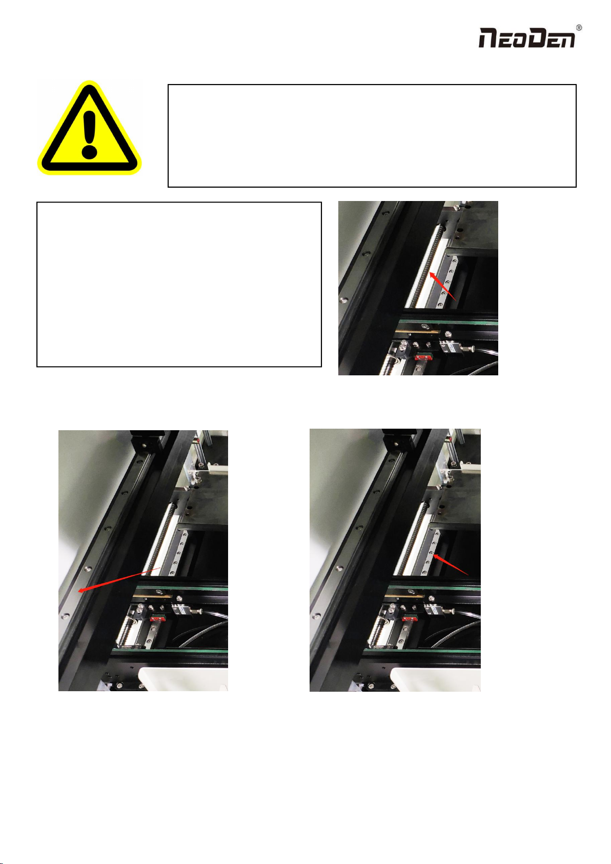
Figure A:the trapezoid screw on the track’s left and right;
Figure B:the line rails of moving load-carrying on the y-axis’s left and rightY;
Figure C:the line rails of moving load-carrying on the track’s left and right;
DEAR USERS:
PLEASE READ THIS USER MANUAL COMPLETELY BEFORE
OPERATING. THIS UNIT AND RETAIN THIS BOOKLET
FOR FUTURE REFERENCE.
Removal of antirust protective film
In order to prevent the equipment from rusting due to
environmental impact during transportation, we pasted a
protective film on the following parts of the machine as
protection. This protective film needs to be removed
manually before the equipment is powered on. If there is
any omission, there will be hidden danger of poor
operation and the possibility of damage;
Figure A
Figure C
Figure B

3
Zhejiang Neoden Technology Co., Ltd
1. Equipment installation and precautions....................................................................................................................................4
1.1 Machine Dimension........................................................................................................................................................4
1.2 Structure of Neoden9......................................................................................................................................................5
1.3 Working Area Structure.................................................................................................................................................. 6
1.4 Important Notice.............................................................................................................................................................8
1.5 Operation flow chart....................................................................................................................................................... 9
1.6 Flow chart of making a programming file....................................................................................................................10
2.PCB Editing............................................................................................................................................................................. 11
2.1 PCB information...........................................................................................................................................................12
2.1.2 Backward................................................................................................................................................................... 12
3.Panelized Board Information...................................................................................................................................................13
3.1 SMD 1 Position Setting................................................................................................................................................ 13
4. Coordinate information...........................................................................................................................................................17
4.1 PCB Mark setting......................................................................................................................................................... 17
1.PCB Mark Point...............................................................................................................................................................17
2. Mark point alignment..................................................................................................................................................... 18
3.Mark Point information................................................................................................................................................... 18
4.2 Component list setting.................................................................................................................................................. 19
5.Feeder Information Setup........................................................................................................................................................ 26
5.1 Function of Feeder Information....................................................................................................................................26
5.2 Feeder setting................................................................................................................................................................27
6. Nozzle Information.................................................................................................................................................................31
7. Assembly Interface................................................................................................................................................................. 31
8. Manual Test............................................................................................................................................................................ 34
9. System Setup...........................................................................................................................................................................36
9.1 Feeder Position Config................................................................................................................................................. 37
9.2 Component Positions Setup..........................................................................................................................................38
10. First trial and test.................................................................................................................................................................. 43
10.1 Program first dry run.................................................................................................................................................. 43
10.2 First production test.................................................................................................................................................... 43
10.3 Component Inspection................................................................................................................................................43
10.4 Continuous SMT production...................................................................................................................................... 44
11. Structure and maintenance instruction................................................................................................................................. 44
11.1 Feeder Brief Introduction........................................................................................................................................... 44
11.2 Installing tape and reel components........................................................................................................................... 46
11.3 Incorrect installation Samples:................................................................................................................................ 47
12.Maintenance...........................................................................................................................................................................49
12.1 Take effective measures to reduce /avoid malfunction.............................................................................................. 49
12.2 Maintenance................................................................................................................................................................50
12.3 Related issues during solder paste printing process...................................................................................................51

4
Zhejiang Neoden Technology Co., Ltd
1. Equipment installation and precautions
1.1 Machine Dimension
Figure 1- Machine dimension
5
Zhejiang Neoden Technology Co., Ltd
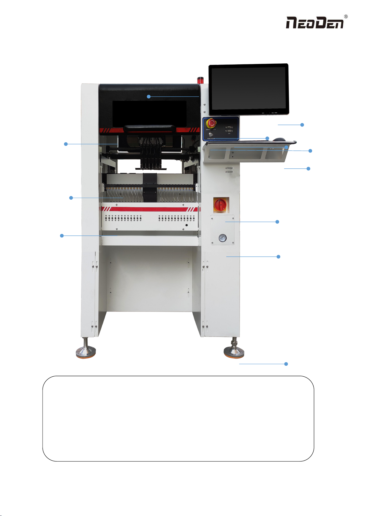
1.2 Structure of Neoden9
Figure 2-Ports and Appearance
(1)Warning Light(Triple Color) (7)USB port
(2)Safety cover (8)Pause button
(3)Front Feeder Slots 1-33(Reference value representation)
(4)Electric Feeder Port (9)Mouse keyboard bracket
(5)Display (10)Power Switch
(6)Emergency Button (11)Air source input
(12)Heavy load pedestal
(8)
(3)
(9)
(1)
(2)
(4)
(5)
(6)
(7)
(10)
(11)
(12)

6
Zhejiang Neoden Technology Co., Ltd
1.3 Working Area Structure
Figure 3- Top view of main mounting area

7
Zhejiang Neoden Technology Co., Ltd
Figure4- X-axis Beam
Figure5- Main Placement Head Camera
8
Zhejiang Neoden Technology Co., Ltd
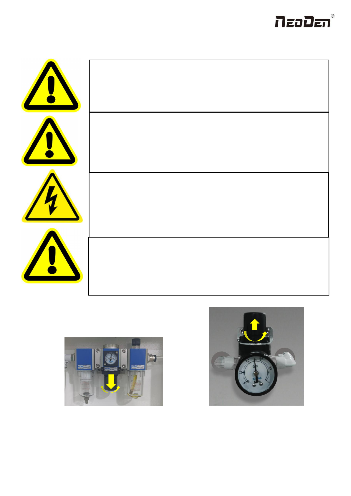
1.4 Important Notice
Figure 6-The air supply of the equipment shall not be less than0.55MP Figure 7- Feeder Pressure 0.5MP
Remark: At 0.55MPA pressure input, the air consumption of the machine is 12L/min. It is recommended to use a
compressed airtank of no less than 70L.
Warning of failure risk of camera identification,please referring to Figure 3 and
Figure 5:The following parts are forbidden to touch and impact
Front IC Camera Back IC camera Left mark camera Right mark camera
Warning of accuracy failure risk, refer to Figure 3: The following components are
prohibited from touching and impacting.
Return to zero column
For the risk of accuracy failure, refer to Figure4: When manually moving XY, it must
be carried out on the X-axis beam moving point;
Warning of electric shock, be sure to follow the requirements below:
Connect the input power supply that meets the requirements of the equipment, the
electrical interface of the machine to the ground must be effectively grounded;
Any time you enter the case and stick to the head for maintenance, you need to shut
down
Warning of equipment life reduction,be sure to follow the requirements below:
When installing the equipment, the equipment must be leveled;
Correct shutdown: shut down the operating software and the system before turning off
the main power switch;

9
Zhejiang Neoden Technology Co., Ltd
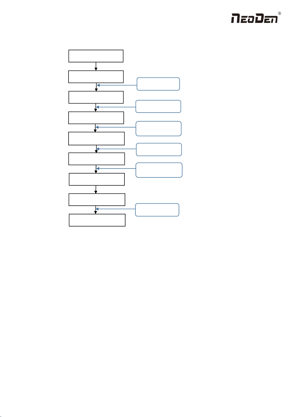
1.5 Operation flow chart
NO.
Flow chart
Note
1
1. The pick and place machine is a precision equipment. In the
installation position of the machine, it is necessary to carry out horizontal
correction before and after the equipment to prevent the uneven operation
of the equipment from damaging the service life of the equipment;
2. Connect and fix the equipment interface before and after the
equipment, and connect and fix the ground wire;
3. The access power must meet the requirements of power identification;
4. No less than 0.55mp air source input and adjust the pressure value to
OK;
5. Check the safety of the working area of the mounting head;
6. The XY transmission parts are not fastened and interfered, and check
that the emergency stop switch is in normal state;
2
Power on and turn the power switch clockwise;
3
1. When the self-test is carried out, the head indicator light of the
mounting head and the light source of the IC camera will be on and
flash briefly to indicate that the self-test is normal;
2.XY initialization (origin reset) is normal, the software enters the file
list interface, and no error report pops up;
4
After power on, directly enter the file list page;
5
See page 13 for the introduction of machine operation for
details;
6
Suggestions on production process:
1. First component confirmation: confirm the component angle
and polarity, component picking position and mounting
position;
2. Start production after confirming solder paste printing and
temperature setting;
7
Production process;
8
After the production is finished, reset the origin and prepare to
shut down;
9
Shut down the system via computer, then power off the
machine.
10
Disconnect the electricity supply after the system being
powered off.
11
Keep the machine clean, daily maintenance of the nozzles
assures high utility.
Software shut down
System shut down
Power OFF
Exit
Production Finished
Preparation
Power ON
Automatic Test
Power on page
Program and Edit;
Production
Shutdown steps
Mounting
Modify
Abnormal
Start-up steps
10
Zhejiang Neoden Technology Co., Ltd
1.6 Flow chart of making a programming file
Note:
A. The basic procedure of making a programming file by manual programming or import coordinate file is similar, but
there are two different parts: component list and fiducial setting.
B. Please find the detailed operation steps of the differences on relative page.
Start
Edit the file
Save and return
PCB feed setting
Feeder settings
Fiducial setting
Penalized PCB first chip
Component setup
See P 12
See P 31
Select file and start
第14 页
See P 14
See P 19
See P 19
See P 26

11
Zhejiang Neoden Technology Co., Ltd
2.PCB Editing
On the file list page, select an existing file for editing or add a new file and name it, select the file for editing, and enter the
editing interface:
File list introduction:
(1) Excel Open:The Excel table of the file can be modified directly in the table for some routine operations,
simplifying the programming operation.
(2) Edit: select a file and click Edit to enter the corresponding editing interface.
(3) Processing: after editing the file, after checking the correctness, select the file and click processing to mount.
(4) Export file: After connecting an U disk, select the file and click Export, after the successful notice pops up, the
export is finished.
(5) Import from U disk: for the files that have been edited offline, they can be directly imported from U disk for
mounting. After connecting U disk, click Import from U disk, select the corresponding files in the new window, and
click OK. When the imported files are showed in the file list, the operation is finished.
(6) Delete: select the corresponding file, click delete, a prompt window will pop up, and click Yes.
(7) Copy: select the corresponding file, click Copy, and the file list will generate a file of xxxcopy1. In order to
prevent misoperation, a new file can be copied before operation.
(8) Add a new file: click Add to open the input window, input the file name, and click OK. At this time, when the file
12
Zhejiang Neoden Technology Co., Ltd
list interface displays new files, the operation is successful.
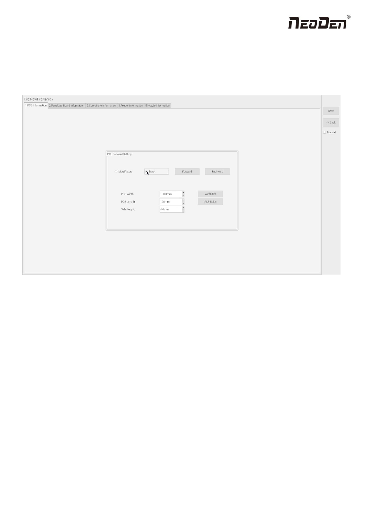
2.1 PCB information
In manual programming, this item is the primary editing item, as shown in the figure:
2.1.1 PCB Forward Setting
Mag Fixture
Select ”Mag Fixture” mode, click “Forward” to feed PCB into the mounting position.
Track
Select “Track” mode, put PCB at the track entrance position and click “Forward”, it will be fed into the stop pin position
(this position can be adjusted manually). Once pcb was stopped, the cylinder will raise pcb and pin return back.
2.1.2 Backward
Click “Backward”, cylinder will descend and pcb be transit to the end of track, it will stop above the sensor position. If
there’s SMT conveyor connected and release signal to pnp machine, pcb will be automatically transit into SMT conveyor.

13
Zhejiang Neoden Technology Co., Ltd
2.1.3 Width Set
Generally setting the width data in this way: pcb width+1mm. Input the data and click “Width Set”, against the tips to check
if it meet with the width back to zero condition. The track will be firstly back to zero width and then widen to the adjusted
data, after that you can put pcb on the track and push it slightly to test if board can be moved smoothly.
2.1.4 PCB Length
It refers to the whole length of PCB. Specially when you need to import the bottom layer coordinates, please firstly input
the PCB length, save it and then import bottom layer, the coordinates will be positive data.
2.1.5 Safe Height
If there’s some special higher component on the PCB, please must set the safe height in case any collision during mounting.
Safe height can be set same as the higher component thickness.
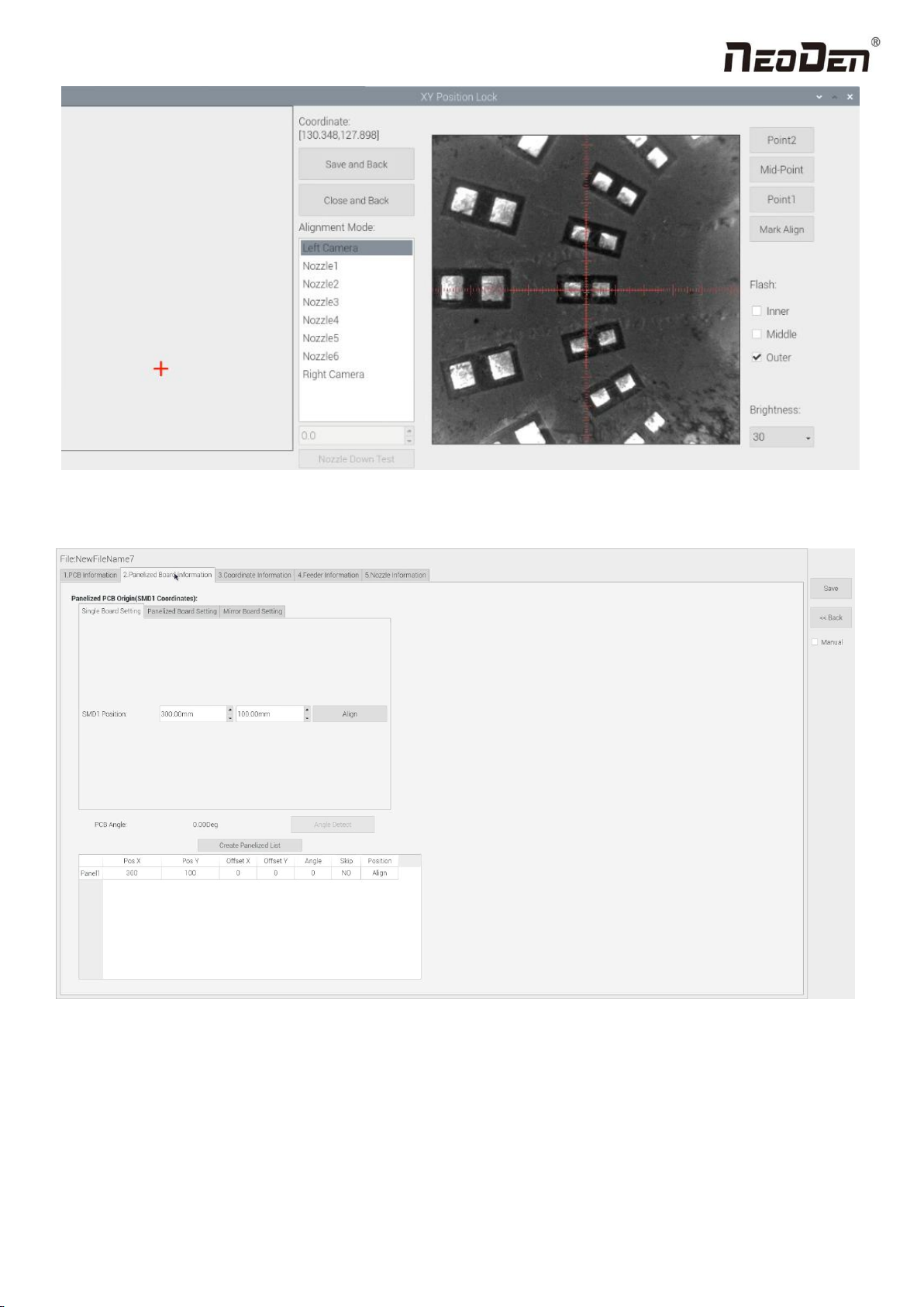
3.Panelized Board Information
3.1 SMD 1 Position Setting
This is mainly to determine the first component on single or panelized PCB of manual program or imported file. The
principle is to collect and calculate the data of each board’s relative spacing, in order to achieve the calculation of the real
coordinate.
3.1.1 Single Board Setting
Click “single board setting”, you will see the “align” button of the SMD1 position that means the first component on the
component setup. Click “align” to enter the vision align interface, we need find the first component that on the component
list, generally we choose the center of the component, see figure:
14
Zhejiang Neoden Technology Co., Ltd
Click “Save and Back”, it will go back to the previous interface, click “create panelized list” button, the data which on the
panelized list will change. Can see the “SMD1 information”on the list and do double check via “align” button.
Notice: when you program under “Manual” mode, as we cannot assume the related PCB to be absolute 90° or 0°, we need
to setting the “PCB angle” (angle deviation of PCB board compares to rails). To minimize the deviation, please select two
points in parallel positions, machine can calculate the PCB angle automatically.
When you program under the mode of import coordinate file, no need to set this step. The default angle under this mode
will be 0°.
15
Zhejiang Neoden Technology Co., Ltd
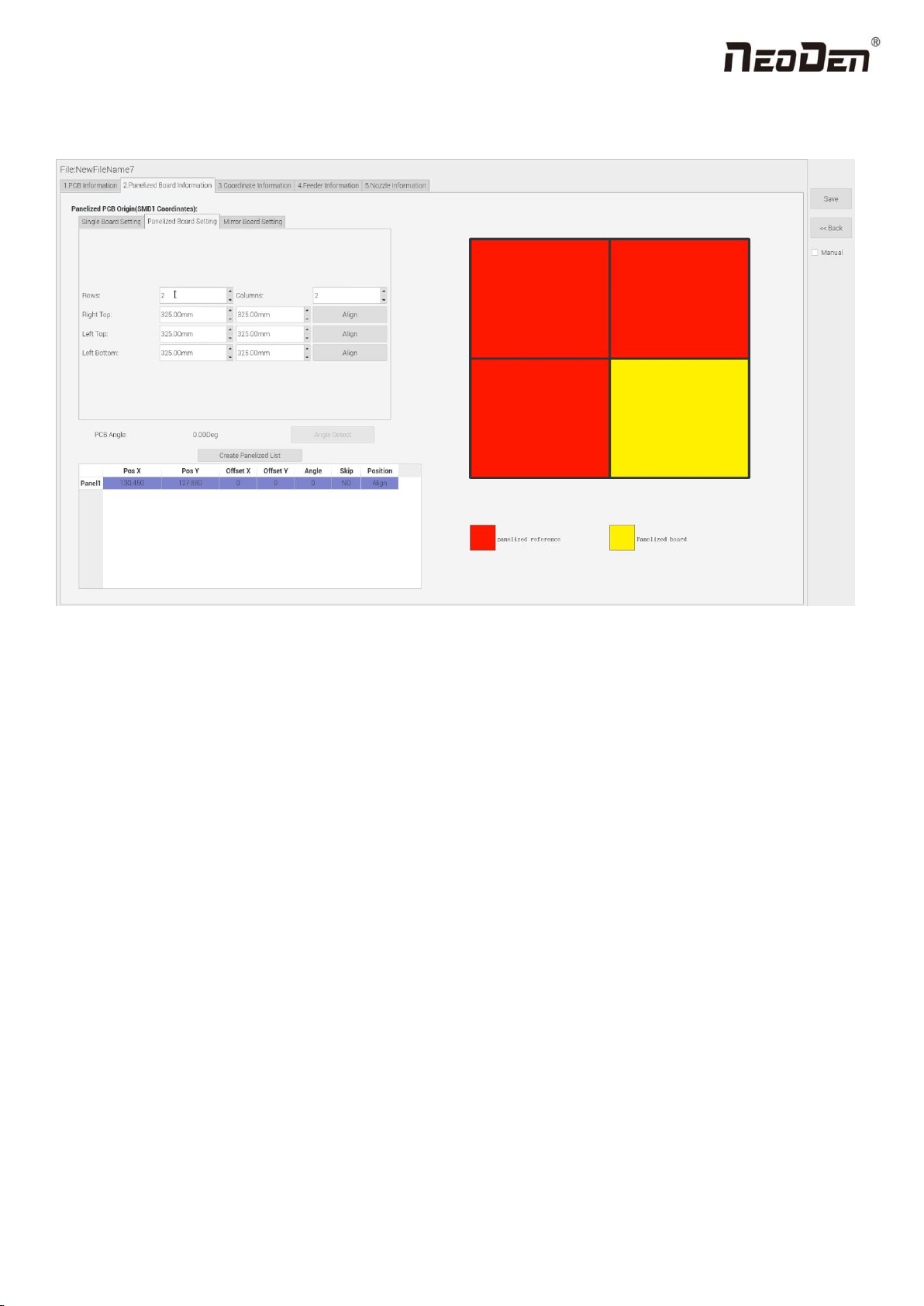
3.1.2 Panelized Board Setting
The steps of the panelized board setting are similar with the single board, but need pay attention to several points below:
(1)The row and column are determined by the positioning of PCB on working area. The direction along the rails is the X ,
the direction perpendicular to the rail is Y , then please enter data in the row and column.
(2)Detailed introduction for each position’s info.:
The data of “left bottom” is collected according to first component in the component list of programming file. Press
“align” of left bottom, find the left bottom panel that is nearest to the left side and nearest to the feeding position, then
find the first component which on the chip list of this panel, align the center of this component. After saving the data, it
will return to the “PCB information” automatically.
The data of “left top”: on the alignment interface, find the left top panel that is nearest to the left side but farthest to the
feeding position, then find the component same as the component that aligned on the “left bottom”, align the center of
this component. Click save and back, it will return to the “PCB information” automatically.
The data of “right top”: on the alignment interface, find the right top panel that is nearest to the right side but nearest to
the feeding position, then find the same component as the component that aligned on the “right top”, align the center of
this component, click save and back, it will return to the “PCB information” automatically.
After setup, click “create panelized list”, the panelized list will be generated accordingly in the blank. You can also double-
confirm each position by clicking “Align”.

16
Zhejiang Neoden Technology Co., Ltd
3.1.3 Mirror Board
The steps of the Mirror board programming are similar with the Panelized board, but need pay some attention to several
points below:
(1)Mirror board includes row panelized and column panelized
Row panelized: several same PCBs are arranged in horizontal direction (X), and the nearby rows are mirrored.
Column panelized: several same PCBs are arranged in vertical direction (Y), and the nearby columns are mirrored.
(2)Panelized Board Row and Column
The direction along the rails is the X axis ,the direction perpendicular to the rail is Y, then please enter related qty data in the
row and column.
(3)Please refer to the data collecting method of each position information as following:
After select the corresponding mirror board panelized method(column or row)and data of column&row,may occur the
situation of the align interface turn to gray and can’t be edited, then no need do position align. Based on actual mirror board
data, right side is showing corresponding images and can find the first component on it.
The data of “right top”on original board: on the alignment interface, find the right top panel that is nearest to the
right side but nearest to the feeding position, then find the first component which on the chip list of this panel, align the
center of this component, click save and back, it will return to the “PCB information” automatically.
The data of “right top”on original board: on the alignment interface, find the right top panel that is nearest to the
right side but nearest to the feeding position, then find the first component which on the chip list of this panel, align the

17
Zhejiang Neoden Technology Co., Ltd
center of this component, click save and back, it will return to the “PCB information” automatically.
The data of “left top”on original board: on the alignment interface,find the left top panel,then find the component
same as the component that aligned on the “right top”,align the center of this component, click save and cancel, it will
return to the “PCB information” automatically.
The data of “left bottom”on original board:on the alignment interface,find the left bottom panel,then find the
component same as the component that aligned on the “right top”, align the center of this component. After saving the
data, it will return to the “PCB information” automatically.
The data of “left bottom”on mirror board:on the alignment interface,find the left bottom panel,then find the component
same as the component that aligned on the “right top”, align the center of this component. After saving the data, it will
return to the “PCB information” automatically.
After setup, click “create panelized list”, the panelized list will be generated accordingly in the blank. You can also
double-confirm each position by clicking “Align”. Note: The angel difference between original and mirror board is 180
degree, original board is 0 degree, mirror is 180 degree.
Skip: For the block component corresponding to the number entered in the panel number (edit box), if no
placement operation will be performed, then select “Yes” in the drop-down list.
Placement: For the block component corresponding to the number entered in the panel number (edit box), if
perform placement operation, then select ‘No’ in the drop-down list.
Recognition: Used for bad board detection. The current bad board detection function is still under development
and cannot be used yet.
4. Coordinate information
4.1 PCB Mark setting
PCB Mark setting interface see below fig.:
1.PCB Mark Point
(1)Panelized mark point
It is mainly used for multiple identical PCB boards consistent of the whole board, when place every panel board, the
machine will rescan small panel board’s mark point.
(2)Single mark point

18
Zhejiang Neoden Technology Co., Ltd
It is mainly used for a single PCB board and multiple identical PCB boards consistent of the whole board (Notice:
coordinate programming is done as a single board) Generally, need to select 2 or 3 mark points.
2. Mark point alignment
(1)Manual alignment:
If the fiducial point quality is poor and the recognition is not accurate, the reference position can be determined manually.
If there is no fiducial point on the PCB, which can through some location holes and set up some special reference point
manually to replace and confirm reference position. Note: Generally use SMD1 coordinate in chip list and the one that is
relatively easy to find far away from SMD1 as fiducial points .In this way, the relative placement effect will be better during
placement, the reference point is determined manually.
(2) Auto alignment
The machine will scan and align fiducial points automatically.
3.Mark Point information
(1)Mark point coordinate
Import the coordinate automatically status: the data collection of fiducial point, which through PCB circuit board to find
fiducial point coordinate information directly, and input directly.
Manual programming status: Select fiducial point on the list and click “align”, enter the image capture page, and then find
the center of the fiducial point via movement, select suitable light source and brightness, click "Mark align" see below
figure, and then click "Save and Back" to go back to main page.
(2)Min, max value

19
Zhejiang Neoden Technology Co., Ltd
It means the size of mark point, it has a floated value, which can prevent recognizing mark point wrongly.
(3)Light source
Light source divide into inner、middle、outer、inner and middle、middle and outer, whole lights. The user can make
adjustments accordint to fiducial point recognition situation.
(4)Brightness
The user can adjust the brightness when align the fiducial point according to actual situation.
Selection of light source and brightness: The user can lock the location of the fiducial point through the XY position lock
interface, select the light source and brightness through the recognition of the Mark camera on the right, and fill the
corresponding parameters into the mark point information.
(5)Range
If there are interference points near the Mark point, you can input a certain value and ensure identify the Mark point more
accurately.
(6)Circle Degree
Input reasonable circle degree value,can avoid interference from other points effectively.
(7)Mode
Dividing into white point and black point, select black point mode if have hole and bright point,select white point mode if
have bright point.
(8)Camera
Support select left camera and right camera(user can select the camera for calibration according to the actual situation),also
can select default setting camera. If user select camera that can’t reach the position, the machine will use corresponding
camera during work.
(9)Mark point add and delete
Click “new” to add new fiducial point(base on mode of the latest fiducial point). Click ”delete” to remove the selected
fiducial point you want.
4.2 Component list setting
Function: display the information and mounting order of components. The components’ quantity and mounting information
can be added through manual programming or importing files , see below figure:

20
Zhejiang Neoden Technology Co., Ltd
4.2.1 Operation introduction of component list
1.Manual programming
(1)Select manual programming;
(2)The component information list displays multiple rows of sample components. First, modify the sample components:
coordinate XY, click the position lock to enter the lock interface. According to the image presented by the Mark camera,
find the corresponding component and confirm the center position coordinates, click save.
(3)Fill in the information of component: Stack refers to which stack No. the component located; Nozzle refers to which
nozzle used to mounting the component; Specification refers to the component’s value; Footprint refers to the common
footprint name as 0402,0603,0805 etc; Skip setting includes true or false, false means keep mounting, true means skip
mounting this component. After finish all parameters’ editing, the setting of first component information finish.
(4)Click ‘New’ to add one row on the component list. The information will exactly copy from last row. Click align to find
the component’s coordinate. Then click save then edit other information such as name, value, footprint and angle etc. Keep
adding new component until the whole PCB finish. Please note that the stack and nozzle do not need to be edited manually.
It can be set through feeder setting interface with ‘Assign all sequentially’ button to assign the information to component list
automatically.
2.Import the processing file
(1)Export the component coordinate information through computer by choosing metric system CSV format to the USB
flash disk.
Table of contents
Other NeoDen Industrial Equipment manuals


Popular Industrial Equipment manuals by other brands


Siemens
Siemens SIRIUS 8WD4428-0BD operating instructions

Nilfisk-Advance
Nilfisk-Advance PEGASUS PZC-M1 Directions for use

Syntec
Syntec 610-E5 Operation manual

Tyco Electronics
Tyco Electronics AMP-O-LECTRIC 690675-2 instruction sheet

Bticino
Bticino 3455 quick start guide

PCB Piezotronics
PCB Piezotronics IMI SENSORS 682 Series operating guide


