Spraying Systems AutoJet ES2500 User manual

AutoJet® ES2500
Electrostatic
Manifold System
OWNER’S MANUAL
MI102012-000
spray.com

TABLE OF CONTENTS
1. Preface········································································································································3
1.1 Important ········································································································································3
1.2 How To Use This Manual ················································································································3
2. Safety··········································································································································3
2.1 General Safety Informaon ············································································································3
2.2 Unpacking The System····················································································································4
3. System Overview·························································································································5
3.1 Introducon ····································································································································5
3.2 Product Features And Specicaons······························································································5
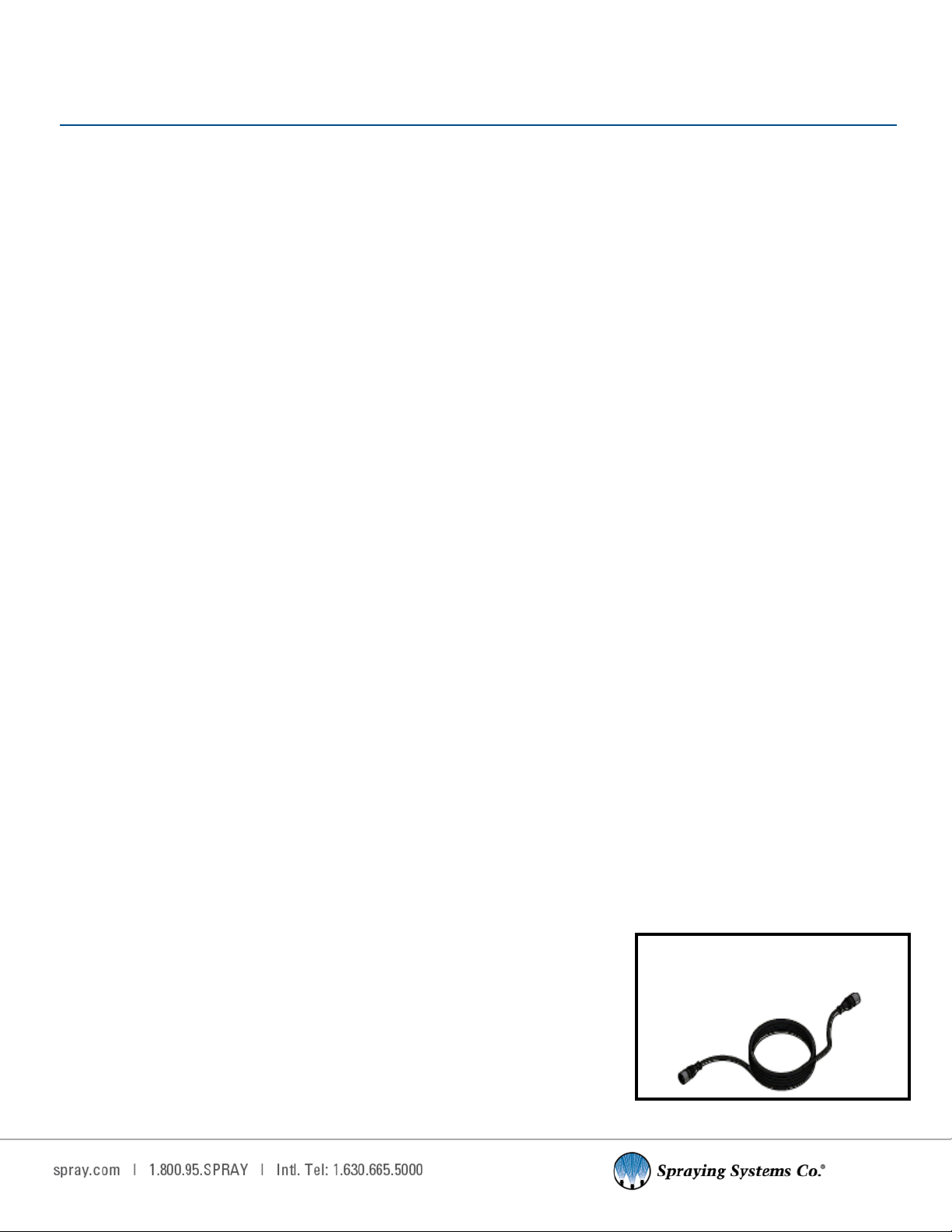
3.3 Encoder Kit (Oponal)·····················································································································5
4. Control Panel································································································································7
4.1 Control Panel Overview ··················································································································7
4.2 HMI Overview ·································································································································8
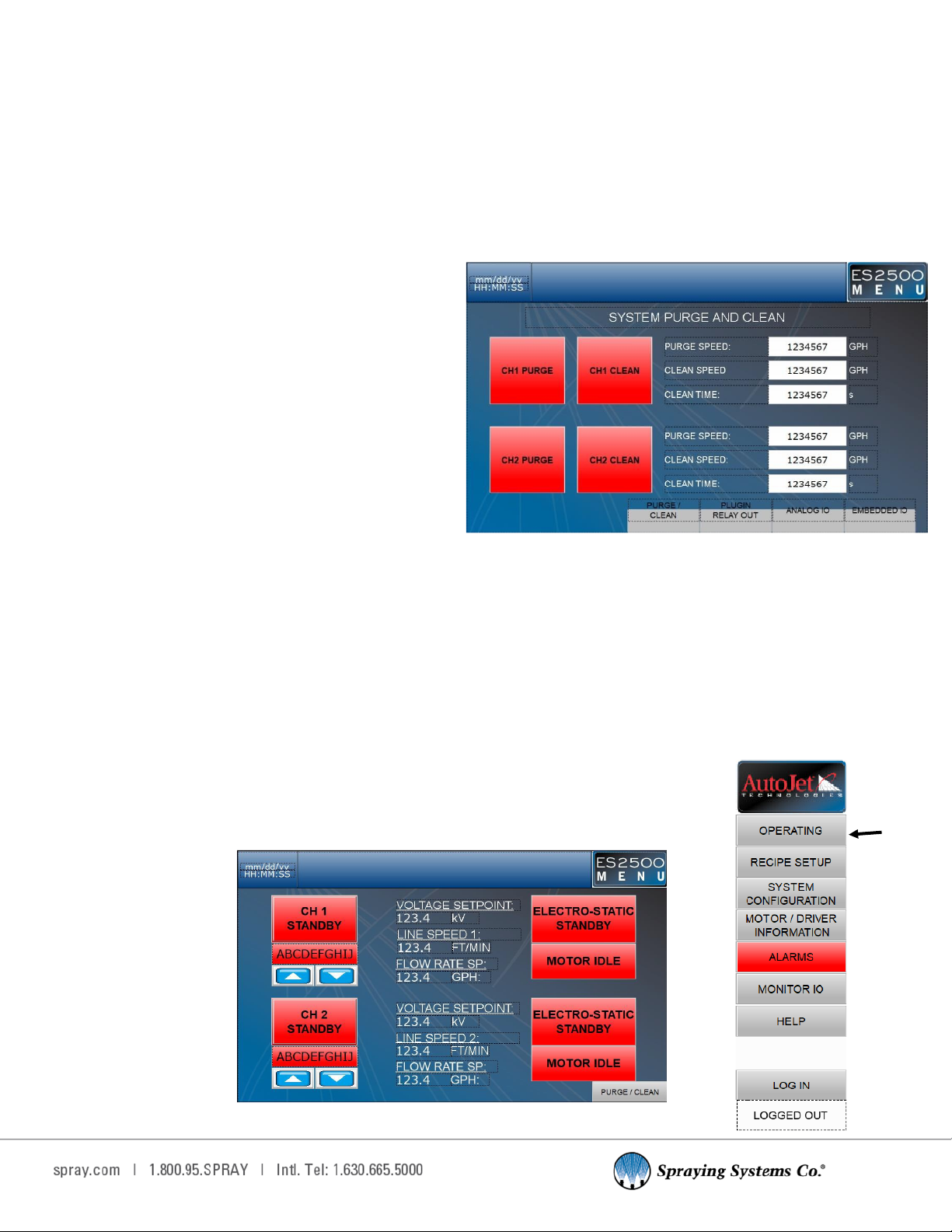
4.3 Purge/Clean Sengs·······················································································································9
4.4 Operang (Home Screen) ···············································································································9
4.5 Recipe Setup ·································································································································10
4.6 System Conguraon····················································································································10
4.7 CH1 Conguraon·························································································································11
4.8 Motor/Driver Informaon ············································································································12
4.9 Alarm Sengs·······························································································································12
4.10 Monitor IO Sengs······················································································································14
4.11 Help Sengs ································································································································15
5. Fluid Delivery Cart ·····················································································································16
5.1 Overview·······································································································································16
5.2 Tank···············································································································································16
5.3 Pump·············································································································································16
5.4 Level Sensor ··································································································································16
6. Manifold ····································································································································18
6.1 Overview·······································································································································18
6.2 Mounng·······································································································································18
6.3 Hook-Up ········································································································································19
6.4 Control Funcons··························································································································20
6.5 Nozzle Conguraon·····················································································································21
6.6 Start-Up Procedure·······················································································································21
6.7 Manifold Disassembly···················································································································22
6.8 Electrostac Manifold Diagram ····································································································24
7. Troubleshoong··························································································································25
8. System Maintenance···················································································································27

3
1.1 IMPORTANT
The AutoJet® ES2500 Electrostac Manifold System are produced, tested, and checked at the factory. The system can
be dangerous if used incorrectly. Read this manual carefully and pay special aenon to any safety instrucons.
Operators must always follow the general safety instrucons in the working area and aim to prevent accidents.
The manufacturer reserves the right to make changes in standard construcon without prior nocaon.
Images and diagrams in this manual may not be exact representaons of your system conguraon.
1.2 HOW TO USE THIS MANUAL
This manual is intended to be a source of informaon for the operators and technicians who may be installing, inter-
acng with or servicing/maintaining Spraying Systems Co.® systems and components.
This manual contains important safety warnings, installaon instrucons, operang instrucons, troubleshoong and
maintenance informaon.
ICONS
WARNING: The user can be seriously injured, damage their health, and/or damage the system.
CAUTION: Product, process, or environment can be damaged or be in danger if the instrucons
are not followed correctly.
ATTENTION: Supplementary informaon for the user that draws aenon to possible problems.
SECTION 1
PREFACE
SECTION 2
SAFETY
2.1 GENERAL SAFETY INFORMATION
READ AND FOLLOW INSTRUCTIONS
All safety-related and operang instrucons should be read before the system is operated. Follow all operang in-
strucons.
SERVICING
Do not aempt to service this system unless you have been trained or authorized to conduct repairs. Only authorized
and qualied service personnel should aempt to service this system. Service by unauthorized personnel may void any
and all warranes.
WARNING: Before performing any maintenance, make sure electrical power is o and any air/
liquid pressure is bled from the system.
UNINTENDED USE
Use of Spraying Systems Co.® equipment in ways other than those described in the documentaon supplied with
the equipment may result in injury to persons or damage to property. Examples of unintended use of equipment
would be:
• Using incompable materials/damaged parts
• Making unauthorized modicaons/using unapproved auxiliary equipment

4
• Removing or bypassing safety guards or interlocks
• Operang equipment in excess of maximum rangs
REGULATIONS AND APPROVALS
Make sure all equipment is rated and approved for the environment in which it is used. Any approvals obtained for
Spraying Systems Co.® equipment will be voided if instrucons for installaon, operaon, and service are not followed.
All phases of equipment installaon must comply with federal, state, and local codes.
PERSONAL PROTECTIVE EQUIPMENT
Spraying Systems Co.® strongly recommends the use of appropriate safety equipment when working in potenally
hazardous environments and chemicals. This safety equipment includes, but is not limited to, the following:
• Protecve hat
• Safety glasses or face shield
• Chemical-resistant safety gloves and apron
• Long sleeve shirt and long pants
Users of this product should never place themselves in the path of the spray. Users should consult and follow the
recommendaons of the Safety Data Sheet (SDS) of any chemical or uid sprayed using this system.
PRESSURIZED SYSTEMS
It is important to recognize proper safety precauons when using a pressurized spray system. When dealing with
pressure applicaons, the system pressure should never exceed the lowest rated component. Always know your
system, all component capabilies, maximum pressures and ow rates.
WARNING: Fluids under pressure can penetrate skin and cause severe injury.
ATTENTION: Always remember to carefully read the chemical manufacturer’s labels, follow SDS and
all direcons.
WARNING OF SHOCK HAZARD
To reduce the risk of electric shock, do not open the cover on electrical control panel. For service contact
Spraying Systems Co.® at 1-866-321-2250.
WARNING: Plug panels into a GFCI outlet.
WARNING: To prevent injury, avoid contact with potenally hot parts. Components can cause
severe burns. Do not aim the spray at any person or part of the body. Do not place any part of your
body into the spray paern.
USE OF CHEMICAL COMPONENTS
Spraying Systems Co. does not manufacture or supply any of the chemical components used in this equipment and is
not responsible for their eects. Because of the large number of chemicals that could be used and their dierent
chemical reacons, the buyer and user of this equipment should determine compability of the materials used and any
of the potenal hazards involved.
2.2 UNPACKING THE SYSTEM
The system components come packaged to protect them from damage. Use cauon when opening the crate. The crate
will contain all parts needed to install the unit. Parts of the unit may be wrapped in bubble wrap. Remove all of the
packaging material wrapping the system. Once unpacked and removed the from the crate, the system is ready for
installaon and connecon.
CAUTION: The packaging may contain exposed cables, hoses, and other components. Always
exercise cauon when opening boxes to avoid accidental damage or slicing of various components.

5
3.1 INTRODUCTION
The Spraying Systems Co. ES2500 is an Electrostac System that ulizes a low ow rate and negavely charged uid to produce
electrostac spraying. The system’s purpose is to deliver a controlled spray with a very high transfer eciency. System applica-
ons include spraying various oils and other coang or lubricang uids onto neutrally charged and grounded metallic targets.
In electrostac spraying, a negave charge is introduced into a uid in the nozzle body using direct contact charging. When this
charge is applied, it causes the uid to also acquire a negave charge. This causes the uid molecules to repel each other, follow-
ing the principle that like charged molecules will repel and opposite charged molecules will aract. This applied negave charge
also causes the uid to be over the Rayleigh limit, which means it will form into droplets as it exits the nozzle orice.
Aer leaving the nozzle orice, the newly formed droplets connue to repel each other—causing the already small droplets to
split evenly into even smaller droplets. This process will connue unl the repulsive force between uid molecules is no longer
strong enough to break the surface tension and split the droplet again.
The ny and uniformly sized droplets retain their negave charges, and will be aracted to any neutral, grounded target nearby
with an aracve force stronger than gravity. Electrostac forces pull the uid droplets towards this target, thinly and evenly
coang the target surface. The average nal drop diameter produced by the Electrostac Manifold is less than 10 microns.
3.2 PRODUCT FEATURES AND SPECIFICATIONS
The ES2500 Electrostac Spray System consists of three main component groups:
• System Control Panel
• Fluid Delivery Cart
• Electrostac Manifold
This manual contains general specicaons and informaon for the ES2500 Electrostac Manifold System. This includes product
overviews, installaon, operaon, maintenance, and troubleshoong informaon.
SYSTEM USAGE
• The ES2500 is designed to run connuously and provide electrostac uid applicaon with high transfer eciency
• Intended uses include spraying a lubricaon oil or a release agent onto a specic metallic target .
• The ES2500 system control panel features a 10” touchscreen HMI
o Operators can control uid ow rate and applied voltage
o System soware has been customized for electrostac spraying, including specic faults and alarms
• The system features two strainer valve assemblies, which allows one strainer to be accessible for cleaning during system
operaon. This limits system downme for maintenance and allows for connuous system use.
3.3 ENCODER KIT (OPTIONAL)
This system can be programmed to use an encoder and control the system with units of distance instead of ming.
Speed/Encoder sengs require a connected line speed encoder. There are two encoders that Spraying Systems Co.
oers, but the customer can also supply their own.
ENCODER SELECTION
The hollow sha encoder will mount in the conveyor, while the wheel and pivot
stye encoder requires the wheel to rest on the conveyor surfaces to measure the
line speed.
SECTION 3
SYSTEM OVERVIEW
M12 (f) x 4 pole M12 (f) cable 5m
(Included in both kits)

6
HOLLOW SHAFT ENCODER
Calculang the calibraon constant—K Factor (pulses/)
K = PPR / CIR (.) = PPR / (PI*DIA)
*Use diameter of drive/tail pulley that encoder is aached to.
K = PPR (*D1/D2) / (PI*D2)
*Used with dual pulley conguraon. D1—Drive/Tail pulley, D2—Secondary pulley encoder is aached to.
Gear rao = D1/D2
WHEEL AND PIVOT MOUNTED ENCODER
Calculang the calibraon constant—K Factor (pulses/)
K = PPR / Wheel CIR (.)
SPECIFICATIONS
Resoluon (PPR) 1024
Output 5-26V push-pull
Input 5-26V
Bore 5/8” hollow bore w/ tether
Bore Inserts Metric 11 mm, 12 mm, 14mm
Bore Inserts Standard 1/4”, 3/8”, 1/2”
Enclosure Rang NEMA4/IP65 (Dust Proof,
Washdown)
SPECIFICATIONS
Resoluon (PPR) 1024
Output 5-26V push-pull
Input 5-26V
Bore 3/8” sealed sha
Wheel Circumference (CIR) 12”
Enclosure Rang IP67 w/ sha seals

7
4.1 Control Panel Overview
The ES2500 Control Panel is used to adjust the parameters of the manifold and adjust the sengs on the uid delivery
cart. Using the HMI screen sengs you can adjust the operaon and conguraon sengs.
PANEL POWER REQUIREMENTS :
Voltage– 120VAC, 3Ph
Frequency- 60Hz
Current– 20A max
ELECTROSTATIC PANEL FEATURES:
• 10” HMI Touch Screen display
• Customizable spray parameters
• Washdown rated
• Three (3) Color Stack Light
• Audible alarm
• Emergency stop buon
• Start/Stop Buon
• System Trigger Buon
SYSTEM CONTROL PANEL LABELED DIAGRAM
SECTION 4
CONTROL PANEL
When the emergency stop buon is
pressed this screen will pop up.

8
Operang Screen Buons
Note: If included in your conguraon, CH2 buons operate in the exact same way as CH1 buons.
Buon Descripon
Channel Current Status:
This buon allows the operator to toggle the system in to run or standby mode. The
buon will appear green while the system is operang.
Recipe Selecon:
The name of the currently selected recipe will appear in the text window. Use the up
or down arrow buons if you need to select a new recipe.
Electrostac Status:
Displays the current operang status of the Electrostac system. This image shows
how the buon is during standby state.
The buon will be green during system operaon.
Motor Idle:
This buon will be red when the motor is o and will be green while the motor is
running.
Purge/Clean:
This buon brings up the system ‘Purge/Clean’ sengs. See the Purge/Clean secon
for more informaon.
ES2500 Menu:
Whenever this buon is visible in the top right-hand corner of the HMI, operators
can open and make selecons from the navigaon menu.
4.2 HMI OVERVIEW
The HMI screens are shown with addional features or opons that may not be included with your system conguraon.
First starng up and aer any system reboot, the Operang screen will load as the system default screen. From the
‘Operang’ screen, you can:
• Trigger Channel standby and run
• View and change the currently selected recipe
• View the voltage setpoint
• View the line speed (If Encoder is connected)
• View the ow rate setpoint
• View the Electrostac system status
• View if the motor is currently running
• Access the Purge/Clean settings

9
4.3 PURGE/CLEAN SETTINGS
The ‘Purge/Clean’ features allows for pump operaon and liquid ow without the acvaon of the High Voltage Pow-
er Supply (HVPS) and Electrostac components.
PURGE
The purge funcon purges the uid lines of air by running the pump to ll the lines with uid. Purge mode should be
run unl uid begins to drip from the manifold nozzles. The purge funcon is to be used during inial installaon to ll
the uid lines, and before each system run when the uid lines have been previously drained. Operators can set the
purge speed in gallons per hour (GPH), and should set the pump speed within the upper range of its maximum ow
seng.
CLEAN
The system should be ushed and cleaned with a fre-
quency determined by system operators. It is suggested
to ush and clean the system at the end of each product
run.
The clean funcon should be ulized when cleaning and
ushing the system. This is because the clean funcon
does not acvate the HV connecon. This allows water
to ush the system.
Operators can set the ow rate for the clean cycle in GPH
and set a me for the duraon of the funcon.
Begin by draining the tank of uid by opening the discharge port of the 3-way
valve at the boom of the tank. Rinse the tank aer uid has been drained.
Add water and a detergent (if desired) to the tank to run through the system
and clean the system lines.
4.4 OPERATING (HOME SCREEN)
All system sengs opons can be accessed through the ES2500 Menu buon at the top of the HMI screen, allowing
system operators to quickly access the sengs and informaon that they need.
The following secons will explain the funcon of each navigaon menu opon.
RETURNING TO THE OPERATING (HOME) SCREEN
Return to the ‘Operang’ screen at any me to see the current system conguraon.
Purge/Clean screen with the oponal two (2)
Channel set up.
Operang screen shown here with oponal CH 2 (second channel) conguraon.

10
4.5 RECIPE SETUP
The Recipes feature allows you to create and save your commonly used spray parameters. The system supports the
creaon and storage of up to 16 customized recipes. Switching between premade Recipes allows for much quicker
transions when changing batches or products that may require dierent spray parameters. Each individual recipe
allows you to:
• Create a name
• Enter the owrate setpoint in gallons per hour (GPH) or based on mL per Sq. Ft. (line speed)
• Enter the Electrostac voltage setpoint in kV
• Set the pump priming me
• Set the desired spray width in inches
4.6 SYSTEM CONFIGURATION
The ‘System Conguraon’ seng allows operators to set system parameters for operaon. For each channel, the op-
erator has control over opons that will aect the system output.
Recipe Setup screen
System Conguraon screen with Mulchannel (2 channels) enabled.

11
4.7 CH1 CONFIGURATION
CH1 HIGH VOLTAGE FEEDBACK SETUP
Note: Ch2 conguraons setup are the same as Ch1 con-
guraon setup.
The operator can set the max voltage output in kV for both the
HVPS and PLC.
CH1 LINE SPEED SETUP
If you are using a line speed encoder with the ES2500, this con-
guraon will allow you to use the device with the system.
See Encoder Selecon for more informaon about encoders.
CH1 HV AMPERAGE FEEDBACK SETUP
This screen allows the operator to set an amperage alarm, if
the amperage exceeds this amount the system will fault.
CH1 LEVEL SENSOR SETUP
Relying on the input data from the uid level sensor, this screen
will allow operators to congure system faults and alarms will
occur based on the uid level in the tank.
Operators can set two separate alarms, the rst alarm will trig-
ger when the uid reaches the set low level percentage, and
the second will trigger when the uid reaches a level that is no
longer safe for system operaon. A tolerance me opon is
also editable.

12
4.8 MOTOR/DRIVER INFORMATION
The Pump Motor and Drive Informaon secon provides operators with current operaonal informaon for the system
motor and sets certain system parameters and view/reset the trip meter.
It allows the operator to set the degrees per step (Deg Per Step) and the milliliters per revoluon (mL/Rev) for the
pump. The informaon on this screen can be useful when troubleshoong the motor.
4.9 ALARM SETTINGS
The ES2500 system noes operators of acve and ongoing alarms at the top of the HMI screen and via stack light illu-
minaon. The Acve Alarms screen, as seen below, lists the me of the fault and the alarm fault code. This screen can
be accessed through clicking the alarm popup at the top of the screen, or through clicking Alarms in the Navigaon
menu. Once resolved, alarms can be cleared by pressing the Alarm Reset buon.
See Troubleshoong secon for more informaon.
Acve Alarms Screen
Motor/Driver Info Screen

13
ALARM HISTORY SCREEN
The Alarm History screen allows operators to view any ongoing or past alarms. This screen will log the me that an
alarm occurs, as well as the specic alarm fault code.
ALARM SETTINGS
Alarm sengs allows operators to adjust the parameters for system alarms. Most alarms have tolerance mes that
are user-controlled sengs. The tolerance me determines how long a certain fault can occur before triggering an
alarm. Operators can also disable certain alarms if desired.
Stack Light
The Stack Light serves as an easy visual indicaon for the current system status of the ES2500. The Stack Light fea-
tures three possible nocaon lights: green, amber, and red. The green and red lights can appear as either a solid or
ashing illuminaon.
• Green: When the stack light is green, it represents normal system condions.
- Solid green- the system is ready for operaon
- Flashing green- occurs during system operaon.
• Amber: When the stack light is displaying an amber light, it represents that the system is not ready for operaon.
• Red (Warning): The stack light appears red when
there is a system fault and the Emergency stop
buon is deployed.
- Solid red- a standard system fault
- Flashing red- a crical system fault.

14
4.10 MONITOR IO SETTINGS
When Monitor IO is selected from the Navigaon menu, the rst screen you will see is “Embedded IO Monitor” as
seen below. This screen provides live readings of both the analog and digital aspects of the PLC. This screen can pro-
vide useful informaon when troubleshoong system components.
PLUGIN RELAY OUTPUT
This screen displays output relays that can also be toggled on or o. These opons can be helpful for troubleshoong
purposes.
IO Informaon

15
ANALOG IO
The Analog IO screen displays current analog values for the controller, which can be useful for troubleshoong pur-
poses.
4.11 HELP SETTING
Selecng ‘Help’ from the navigaon menu will bring up a screen that displays system informaon, access the HMI OS,
Screen Map, and change password proles.
SCREEN MAP
The Screen Map displays all possible screens
within the ES2500 menu. It allows operators to
select any sengs.
The ‘Help’ screen also displays the current PLC soware version.

16
5.1 OVERVIEW
The uid tank features a level sensor to monitor and produce a fault when the
uid falls to a low level. The tank also features a 3-way ball valve at its outlet for
uid draining and cleaning purposes.
Fluid Delivery Cart Dimensions: 40.500” x 31.263” x 54.502”
5.2 TANK
Tank is mounted using 4 3/8” -16 screws
TANK SPECIFICATIONS:
Capacity: 15 Gal, Cone Boom
Material: Polyethylene
Dimensions: 16” x 16” x 24”
5.3 PUMP
The ES2500 pump comes standard with one pump to power uid delivery to the Electrostac Manifold(s). It has a mo-
tor driven, progressive cavity pump, with speed adjusted by the ES2500 control panel for desired ow.
PUMP SPECIFICATIONS:
Max ow: 10 GPH
SET-UP
Pump gets fed from the tank with a 3/4” Tygon hose.
ATTENTION: Viscosity of the uid being sprayed may have a signicant impact on the pump specica-
ons.
5.4 LEVEL SENSOR
The level sensor sends a signal when the tank gets low to let the control panel know when to shut o the system to
prevent the pump from running dry and becoming damaged. The level sensor gets wired into the ES2500 control panel
by cable.
See CH1 Conguraon secon for seng parameters in the control panel.
CONNECTING THE LEVEL SENSOR TO THE CONTROL PANEL
1. Connect power to the controller.
2. Plug the level sensor cable into the sensor mounted to the main tank unit.
3. An NPT thread push tube ng needs to be added to the air inlet port on
the boom of the controller provided by the customer. Air must be supplied
to the air inlet port.
4. The auto-rell controller unit will supply air to the pneumac valve when
the main tank level is low. In that case, the yellow light on the controller will
illuminate indicang the automac rell has been triggered and is currently
lling.
5. Supply air to the inlet on the control box (0-100 PSI max.)
SECTION 5
FLUID DELIVERY CART
Strainer
Fluid Tank
Pump/Motor

17
PROGRAMMING THE LEVEL SENSOR
The tank level sensor comes pre-programmed. However, the set points (Q1 – SP1 and Q1 – RP1) can be adjusted to
congure the system specically for the applicaon.
The level sensor displays the tank level as a percent (%) full. However, all parameters are measured in millimeters
(mm) from the boom of the probe. The usable range of the level sensor is between 10 mm and 410 mm from the
boom of the probe, a 400 mm range.
There are two switching outputs that can be adjusted: Q1 and Q2. Output Q1 is used for the Auto-Rell feature and
output Q2 is used for the Low Tank Level indicator.
To access the above parameters from the main display (% full), press and hold the “Set” buon. Use the up and down
arrows to navigate to “Q1MENU” or “Q2MENU” and press the “Set” buon. Use the up and down arrows to navigate
to “SP1” or “RP1” (or “SP2” and “RP2”) and press the “Set” buon. Use the up and down arrows and the “Set” buon
to change the numeric values assigned to the given parameter. Instrucons for seng other parameters can be found
on pages 32-35 of the provided component manual.
Assuming the tank has been inially lled and given the values in the above table, as the system is being used the level
in the tank will decrease. Once the uid reaches 250 mm from the boom of the probe, 63% full (100% * (250-
10)/380=63%), Auto-Rell will turn on. As the uid level rises and reaches 390 mm from the boom of the probe,
100% full, Auto-Rell will be turned o.
If Auto-Rell is switched o or the supply is interrupted, and the uid level reaches 10 mm from the boom of the
probe, 0% full, the Low Tank Level indicator will turn on. This is intended as a warning that the system is not automa-
cally relling. The Low Tank Level indicator will turn o once the uid level rises above 50 mm from the boom of the
probe, 10% full.
Menu Parameter Name Descripon Preset
Expert Probe Probe Length Length of probe for this applicaon 457 mm
Qa QAHIGH High Level 20ma Maximum tank level (QAHIGH>QALOW) 380 mm
AutCal
Qa QALOW Low Level 4ma Minimum tank level 10 mm
Qa QAPOL Congure Analog output signal as congured QA-Nrm
Qa QATYP Congure Seng the output signal Auto V
DspVal Length Congure Display shows ll level in % %
Q1 SP1 Switching Point 1 High Level - Auto-Rell stops lling 380
Q1 RP1 Reset Point 1 Low Level - Auto-Rell begins lling 76
Q1 OU1 Switching Funcon Output Type - Normally Open/Closed Qx-Hnc
Q2 SP2 Switching Point 2 Not Low Level - Indicator will turn o at or 50
Q2 RP2 Reset Point 2 Low Level - Indicator will turn on at or below 10
Q2 OU2 Switching Funcon Output Type - Normally Open/Closed Qx-Hno

18
6.1 OVERVIEW
In electrostac spraying, a negave charge is introduced into the uid in the manifold body via a central charging elec-
trode. This causes the liquid to become negavely charged, which will then cause the uid molecules to repel each
other.
At the manifold orice, the uid forms into a ny cone. A single stream of droplets will be propelled away from the
orice due to their negave, repelling charge. The droplets will connue to repel each other as they descend, causing
the small droplets to break up into even smaller droplets. This will connue unl the repulsive force between the mol-
ecules is no longer strong enough to break the surface tension and split the droplet.
Yet, these ny and uniformly sized droplets sll retain their negave charge. These uid molecules will be aracted to
any neutral and grounded target nearby through an aracve force stronger than gravity. This electrostac force pulls
the liquid molecules evenly towards the target, coang the surface and providing a very high transfer eciency.
SPECIFICATIONS:
• Width– 6”, 12” or 24” modular secons
• Orice Size– 0.020” (0.51 mm) or 0.030” (0.79 mm)
• Flow Rate (per manifold)- 0.1-20 cc/min per manifold
• System Sizes– 6”, 12” 18”, 24”, 30”, 36”, custom sizes available (combined width, all manifolds)
6.2 MOUNTING
ADJUSTABILITY
The mounng locaon should allow the operator to be able to view the Electrostac Manifold while at the control panel. This will
allow for easier adjustments and ne tuning of the electrostac spray, as the operator will be able to easily see the result of
changing system parameters.
When posioning the uid delivery cart, be aware of its distance from the system control panel mounng locaon—there is a 7-
meter maximum cable run. The uid delivery cart is equipped with caster wheels for easy posional adjustments if needed.
The ES2500 Manifold has been designed to have a high degree of adjustability and can be congured as needed. The
user can control the following:
• The applied voltage
• Fluid ow rate
• The intensity of the electrostac eld
• The height of the Manifold from the target
• Rotaon of the Manifold around its axis for 360-degree coverage
The end mount blocks are pre-drilled with a set of 1/4-20 UNC threaded and 0.266” dia. through holes. These can be
used all together, or in part, to mount the assembly from the top, sides, front, and back.
The more degrees of movement that are built into the mounng scheme, the easier it will be to adjust the spray width
and achieve even uid ow. The nozzle assembly should be able to slide vercally from between 3” to 14” from target
and should be able to rotate from 0 to 90 degrees to the target.
ATTENTION: Nothing metallic or conducve, with excepon to the target, should be within an 18”
envelope of the nozzle. This includes mounng xtures, which should be made of plasc whenever
possible.
SECTION 6
MANIFOLD

19
6.3 HOOK-UP
FLUID LINE
Tubing must be made from a material that is compable with uid to be
sprayed, as well as rigid enough to work with the 1/4” OD tube push-to-
connect ngs that are supplied with nozzle assembly.
ATTENTION: Metallic tubing is not to be used as it will in-
terfere with the electrostac elds and skew the spray or
potenally trip the AccuJet Electrostac Controller. All uid
must be run through a lter capable of removing 90-micron
parculates.
HIGH VOLTAGE CABLE
One side of the nozzle body has an electrode connector like the top of a
spark plug. This plugs into the boot on the high voltage cable. Inside the
rubber boot is a steel fastener. Be sure this fastener is rmly aached to the elec-
trode.
Manifold Fluid Line Connecon

20
GROUND WIRE
The ground wire assembly should come connected to the ground rods with 7/16 hex head bolts on each end of the
conveyor nozzle assembly. The ground wire assembly should be connected directly to an earth ground as dened by
local electrical codes.
6.4 CONTROL FUNCTIONS
VARIABLE ELECTROSTATIC FIELD
The nozzle bodies can be slid up and down inside the end blocks by loosening the 4 plasc thumb screws on both
ends of the assembly. This allows for minor adjustments toward and away from the target, and to increase or de-
crease the eects from the ground rods on the electrostac eld. The ground rods themselves can also be moved in-
ward to increase the eect.
ELECTROSTATIC VOLTAGE
The ES2500 Manifold is rated to work with a voltage from 0-30,000V. This wide range ensures that a variety of uids
will achieve atomizaon and allow for adjustment for spray paern and drop size.
WARNING: DO NOT exceed voltage rang for manifold nozzle assembly; serious injury or death may
occur.
MANIFOLD SECTIONS
Fluid is fed in through the push-to-connect ng directly in the
center of each manifold secon.
The ES2500 Manifold is available in 6”, 12”, and 24” long sec-
ons. These secons can be used individually, or combined, to
create a size that matches the desired spray coverage area.
Examples of possible Manifold conguraons.
Table of contents
Other Spraying Systems Industrial Equipment manuals
Popular Industrial Equipment manuals by other brands

Beko
Beko BEKOMAT 3 E Ex Installation and operating manual

Teryair
Teryair 1VMS Series Operation and maintenance guide

Wopa
Wopa SA0061 user manual

ABB
ABB HT583272 Operation manual

Trumpf
Trumpf TruPlasma RF 1001 Operator's manual

Dillon Precision Products
Dillon Precision Products Super 1050 instruction manual