MBS Thermo IN User manual

INSTRUCTIONS FOR INSTALLATION AND MANUAL
Solid fuel stove for central heating THERMO IN

To respected customer,
We are very pleased for your trust and your decision to buy our product.
You made a good choice, because stove Thermo In has technical characteristics
which classify it into the very top of its class, providing advantage within its
competition.
Please, read carefully this instructions before you use Thermo In, in order to find
hints and tips for proper handling and maintenance.
We also believe that you will put your signature in the book of satisfied customers of
our products.
"Milan Blagojević" AD
Smederevo

CONTENTS
Warning before use……. ..........................................................1
Stove description.......................................................................2
Installation ................................................................................4
Installation of stove into the system for water heating...............6
Operation .....……..........…………………..................................10
Procedures for ignition and lighting …….................……...........11
Cleaning and maintenance .......................................................12
General notes ...........................................................................13
Advices for environmental protection ........................................13

WARNING BEFORE USE
In order to put your stove in regular operation, it is very important to read these
instructions and observe instructions for use and handling.
For combustion, use solid fuel like wood, briquette, but not stone coal due to its high
calorie combustion power.
It is forbidden to put explosive devices and materials into the firebox or onto the
stove hotplate.
It is forbidden to keep inflammable materials within the close vicinity of the stove.
For proper combustion, within the normal operational mode, draught in the chimney
should be 15-17 Pa. In case if draught is higher then 20Pa, it is necessary to install
chimney flap.
Room in which stove is located should be regularly ventilated due to flow of fresh air
necessary for combustion.
Parts of stove are heated within period of operation and appropriate handling
precaution is necessary. Do not allow children to handle and play in the vicinity of the
stove.
Do not allow handling with the stove to the persons with limited physical and
psychical abilities.
Do not allow pets to be close to the device.
Only spare parts approved by the manufacturer may be installed onto the furnace.
One may not make any changes to the furnace.
Upon the first heating, smoke and various scents may occur, especially on the
surfaces protected with the color and other anti-corrosive primers. Ventilate the
room.
Thermal regulator is integral part of the stove and set-up at the factory. Do not make
any adjustments of thermal regulator by yourself.
When adding fuel, open fire door for only few degrees, wait 4-5 seconds until
pressure in the firebox and room comes equal, then open it wide very slowly. Do not
open the door abruptly, so when flame is strong in the firebox it may come out of the
firebox. Do not open firebox door unnecessarily, always paying attention to open it
when flame is weak.
In case of non-observance of these instructions for use, manufacturer will not
be liable for any damage on stove.

STOVE DESCRIPTION
Figure 1. Integral parts of Thermo IN furnace
1 – ashtray
2 – ashtray door
3 – thermo-regulator button
4 – grate handler
5 – natural stone hotplate
6 – fume outler
7 – fire door
8 – auxiliary regulator
9 – handles
10 – glass cleaner
11 – heating-up area
12 – fire door glass

Solid fuel stove for central heating Thermo IN is made and tested according to the
European standard EN 13240. Figure 1 shows appearance of stove with integral
parts important for handling and use. Table 1 gives its technical characteristics.
Table 1. Technical characteristics
No. Technical characteristics
1 Nominal thermal power (kW) ______________________19
2 Efficiency (%)
wood_________________________________________88
brown coal_____________________________________87
3 Thermal power transferred to water (kW) _____________11
4 Thermal power transferred to environment (kW) ________8
5 The average CO value (taken from 13% O2):
wood _____________________________________0,09 % 1,156 g/m³
brown coal _________________________________0,11 % 1,427 g/m³
6 Dust emission:
wood __________________________________________0,068 g/m³
brown coal ______________________________________0,065 g/m³
7 Dimensions – W x H x L (mm) _______________________590x1000x540
8 Dimensions of firebox – W x H x L (mm)________________408x320x390
9 Quantity of water in boiler (l) _________________________23
10 Diameter of fume outlet (mm) ________________________120
11 Water adapters (”) _________________________________1
12 Draught (Pa) ____________________________________15 -17
13 Average flue gases temperature (°C) _________________123, 1
14 Maximal water temperature (°C) ______________________90
15 Recommended fuel______________________________ wood, briquette
16 Consumption at nominal power (kg/h) ____________________6
17 Max. working pressure (bar) ____________________________2
Solid fuel stove Thermo IN is intended for heating of residential premises. Valve for
thermal exhaustion is integral part of installation which serves as overheating valve.
Thermal valve Caleffi 544 1/2 is recommended and displayed on Figure 2.
Comment: Thermal valve is not part of the product and not supplied with it. Boiler
guarantee is valid exclusively with built-in thermal valve.

Figure 2
Central heating stove Thermo IN possesses boiler with the 23l capacity made of
standardized boiler metal-sheet. With such this production improves boiler life span.
Water adapters are 1“.
Work table of stove is consisted of plate made of natural stone (figure 1, position 5)
with cast adapter for smoke exhaust (figure 1, position 6) which is mounted on plate
by two screws.
Fire door (figure 1, position 7) are cast and has thermal-resistant transparent glass
(figure 1, position 12). Ashtray door (figure 1, position 2) is cast and has auxiliary air
flow regulator (figure 1, position 8).
Below the plate, there is area for heating-up (figure 1, position 11) with surface
made of natural stone. This area is suitable for heating-up of food in small vessels,
and to maintain temperature of hot drinks.
INSTALLATION
Stove may not be placed in the close vicinity of wooden elements, air-condition
devices or plastic parts of the furniture, because it transmits (during combustion)
high working temperature which distributes at the external surface of the stove.
Minimal distance between stove and surrounding elements is 50 cm, and
inflammable materials 140 cm.
If foundation on which stove will be located is made of easily-inflammable materials
(wood, warm floor, laminate...) it is necessary to install special protection larger then
the base of the stove. - lateral side min.10 cm, in front of the stove 50 cm.
Stove is to be connected with the chimney by appropriate smoke pipes through
adapter on the upper side of the cast hotplate, in order to provide adequate tightness
and smoke flow from the stove to the chimney. Smoke pipe may not be installed too
deep into the chimney in order not to reduce surface of cross-section thus preventing
draught in the chimney.
Prior to installation of stove, check chimney draught since it is one of key factors for
proper operation. Draught depends on integrity of the chimney and meteorological
conditions.
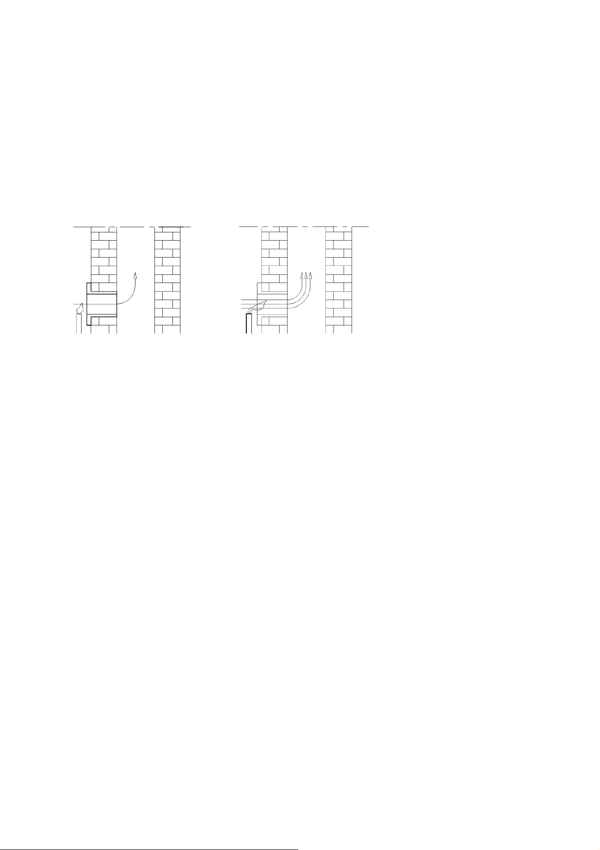
One of the simplest ways for checking of draught in chimney is by candle flame, as
described on figure 3. Candle flame is to be put close to adaptor opening of chimney
and if it flickers toward opening, draught is satisfactory (figure 3.2). Weak flickering of
the flame is indicator of weak draught (figure 3.1).
Figure 3.1 Figure 3.2
If draught in chimney is weak (Figure 3.1), check correctness of the chimney.
Chimney should be located in the interior of the room, and id it is on external walls of
the room, chimney insulation is highly recommended.
Faults of the chimney may be (figure 4.1):
1. Weak windshield,
2. Strange body or bulges in the chimney,
3. Chimney chaps,
4. Accumulated tar,
5. Non-tightness of adapters and cleaning openings,
6. Smoke pipe installed too deep,
7. Fireplace without door or some other opening on chimney and non-tightness
of connecting and other cleaning openings.
8. Non-tightness of connecting and cleaning openings.
Distance between two adapters on the same chimney must be minimum 50 cm
(Figure 4.2).
On figure 4.2 example of proper chimney is described.
Devices which use gas as a fuel may not be connected to the very same
chimney.

Installation of stove into the system for water heating
- For water inlet and outlet within the system of floor (central) heating are provided
with adapters on boiler 1".
- Thermo IN may be installed on closed or open system of central heating.
Installation on closed central heating system
One of the aspects of mounting installations is depicted on figure 5.
- Safety valve must be installed in the vicinity of boiler and must be adjusted for
pressure of max. 3 bars. External guide of safety valve must be as shorter as
possible and may not have possibility to be closed. Within this guide, also, there may
not be single valve or any other armature.
- Closed expansion vessel is to be installed in the vicinity of boiler and its safety
guide is short. Volume of this vessel is determined according to the capacity of boiler
and regarding ratio 1kW:1l.
- Installation of thermal valve in its provided place on the boiler is mandatory. We
recommend thermal valve Caleffi 544.

Figure 5
Scheme of closed central heating system

Installation on open central heating system
One of the aspects of installation is depicted on figure 6.
At this system, starting guides are to be mounted in sequence, safety distribution
guide of expansion vessel and boiler valve, and on starting guide of the system
boiler valve, pump and valve are to be installed. Directly below opened expansion
vessel, short connection should be installed between safety distribution guide and
safety retracting guide, which provides freezing of water during winter in the
expansion vessel.
On safety distribution and safety retracted guide, there may not be any armature.
Expansion vessel itself must possess overflow pipe as seen on scheme on figure 6.
Volume of expansion vessel is determined by the pattern:
V = 0,07 x V water, (l), where V water is volume of water in entire power plant.
Open expansion vessel is to be installed vertically above the highest heating body.
At the opened system of heating, gravitation system of heating is possible.
Comment: Installation of heating and putting into operation of entire system is to be
checked exclusively by trained person who guarantee proper operation of entire
heating system. In case of poorly designed system and eventual omissions in
installation by that person, complete material responsibility shall bear exclusively the
person entrusted for the installation of the heating system, not the manufacturer,
representative or retailer of the boiler.
Important
• Stove installation should be carried out by skilled person according to the
appropriate design. Structure of stove enables connection on closed or opened
heating system. All connections must be well sealed and tightened. Prior to putting
into operation, complete installation should be tested with water under pressure of 3
bars.
• Upon installation of safety valve, pay attention to direct connection with water
supply network and sewage, as well as on the fact that valves (taps) always must be
open.
• If reinforced hose for connection with drainage outlet is used, it must be away from
the back side of stove.
Upon first ignition, it is necessary to test accuracy of the valves by short-time pre-
heating up to 100°C, to test accuracy of draught regulators and installation for
distribution of hot water to radiators, as well as radiators themselves.

Figure 6
Scheme of open central heating system

MANAGING STOVE OPERATION
Pace of combustion, as well as quantity of heat transmitted by the stove, depends
on the quantity of primary air for combustion which is brought into the area below
firebox. Regulation of quantity of primary air is provided automatically using thermo-
regulator Rathgeber (figure 7).
Figure 7
Upon ignition, turn regulator button into position of maximally opened flap in
direction displayed on figure 8. During operation, depending on temperature,
regulator flap will open and close automatically. If lower temperature then adjusted is
desired, turn regulator button in desired position of minimally open flap, thus
regulator flap closes. Button is to be turned with auxiliary tool while longer side of the
tool is to be put into the rifle of button by turning, as desired. (Fig. 8.)
Figure 8
If there are disturbances in burning (weak fuel, remaining malfunctions for proper
operation of stove) then through auxiliary regulator, which is located on front side of
the ashtray door (figure 1 position 11), we can bring some additional primary air, thus
improving combustion.

PROCEDURES FOR IGNITION AND LIGHTING
Prior to the first ignition, clean all enameled surfaces of the stove by dry mop in
order to avoid combustion of dirt on stove and creation of undesirable scents.
Note:
Upon first ignition, there may be slight smoking, especially at colored surfaces. All
cast parts are protected with thermo-resistant color which obtains its stability after
few ignitions. Thereupon, there may be gases which could be removed by simple
ventilation of the room.
Ignition in the firebox is to be carried out as follows:
- open the fire door and ashtray door,
- put into the fireboxal for enkindle (chopped wood, dry paper),
- carry out enkindling,
- close the firebox and ashtray door,
- upon creation of basic cinder, put into the firebox some massive pieces of wood
and close burner door. If briquettes are used, you must wait for all fuel quantity to
burn, then reduce air intake to half.
For ignition and lighting, you may not use light distillate oil, gas and similar, so then
conditions for origination of explosive gases may occur in smoke channels of the
stove and chimney.
For burning, we recommend wood and briquettes.
Do not use organic waste as fuel, food residues, plastic objects, inflammable and
explosive materials, whose combustion disturbs proper operation of stove and may
induce damages and pollution of environment.
Increased external temperatures may induce weak air flow (draught) in the
chimney, so it is recommended to frequently burn smaller quantities. We recommend
burning every 1h with height of the fuel in the firebox up to 15cm.
After each filling, it is recommended for stove to burn at least 30 minutes with
maximal power, in order to burn all volatile ingredients which are reason of creation
of condensate in the stove in that stage of combustion.
For proper work of stove it is necessary to:
- regularly clean furnace and chimney
- regularly ventilate rooms due to good combustion

- regularly remove ash from ashtray
- to regularly remove gravel and non-combusted materials from the firebox, with
cleaning set
Accumulated gravel and non-combusted materials should be regularly
removed from the firebox, by cleaning set.
CLEANING AND MAINTENANCE
Through regular and proper cleaning, you enable proper operation and stove life
span.
Cleaning of external surfaces
Enameled and chrome surfaces are to be cleaned with soft mop which will not
damage these surfaces. Cleaning agents of chemical origin do not damage surfaces
of stove and may be used.
Cleaning of internal surfaces
Upon cleaning of stove, use protective gloves. Clean internal walls of the firebox
and remove accumulated tar, collect particles and non-combusted pieces from the
firebox, clean ashtray and ash accumulated in the interior.
Glass cleaning
Upon combustion of fuel, glass surface may become dirty due to products of
combustion. Glass should be cleaned when it is cold, by soft detergents. Abrasive
agents damage glass thus do not us them.
GENERAL NOTES
If all instructions for installation, regulation during operation and cleaning directions
given in this manual are fulfilled, stove represents approved and safe device for
using in the household.
All reclamations, evaluated as defects or weak functioning of the stove, should
report to manufacturer or authorized service by phone or in written with fiscal receipt.
All contact information is given at the end of this manual.
Each defect of stove should be removed exclusively by manufacturer or authorized
service.
If unauthorized persons make any servicing or any other repairs and changes on
the stove, owner of stove loses his right for guarantee by the manufacturer.
Procurement of spare parts is to be done exclusively through manufacturer’s
service, based on positions and figures in this manual or designation of mentioned.
Manufacturer does not bear any liability if customer does not observe instructions
for use and installation of the stove.

ADVICES FOR ENVIRONMENTAL PROTECTION
Packing
- Packing material may be 100 % recycled.
- Upon disposal, observe local regulations.
- Packing material (plastic bags, parts made of polystyrene-styropor etc.)
should be kept away from children, since it may represent potential harm.
- Wooden battens which are the case of transport packaging are connected with
nails!
Pay attention on injuries during disassemble and disposal of wooden packaging.
Product
- Device is made of materials which may be recycled. Upon disposal,
observe local environmental laws.
- Use only recommended fuels.
- Combustion of non-organic and organic waste (plastic, chip,
textile, oiled wood etc.) is strictly forbidden, since when combusted, they release
cancerous and other harmful materials.
A.D. “Milan Blagojević” Smederevo
Đure Strugara 20
11300 Smederevo
tel: +381 26 633 600
+381 26 633 601
fax: 026 226 926
e-mail: office@mbs.rs
www.mbs.rs
Table of contents
Other MBS Stove manuals


Popular Stove manuals by other brands

Lacanche
Lacanche Fourneau "Rully" Installer manual

EdilKamin
EdilKamin Blade2 12 Up Directions for installation, use and maintenance

Dovre
Dovre 280 Instructions for use installation and servicing

Omega
Omega Omega user manual

New Buck Corporation
New Buck Corporation GAS STOVE HEATER OWNER'S OPERATION AND INSTALLATION MANUAL

Lotus
Lotus Mondo Series Mounting and user instructions


