MC Electronics MCK 2200 User manual

DPA
SOLID CONTROL MCK 2200
COMPUTER FOR SPRAYERS
INSTRUCTIONS FOR USE
NR.ST2621-EN
REV. 3
EN

Installation and use
SOLID CONTROL MCK 2200
2
This product meets the EMC standards as determined in the
2004/108/EC directive and subsequent amendments and reference to the applied
EN ISO 14982 standard
Manufacturer
: MC elettronica S.r.l.
Address
: Via E. fermi, 450/486
Fiesso Umbertiano (ROVIGO) - ITALY
Tel. +39 0425 754713 Fax +39 0425 741130
E-mail: [email protected]
Internet: www.mcelettronica.it
Manual code
: ST2621-EN
Issued
: July 2013
Edition
: October 2021
MC elettronica S.r.l. is not obliged to give notice of any further modifications of the
product.
The information given in this manual does not allow unauthorized personnel to tamper
the product in any way.
The guarantee on the equipment will no longer be valid if tampering should be
detected.
© Copyright MC elettronica 2021
2 LED for millesimal scale
3 LED for centesimal scale
4 Mechanical adjustment of the instrument
5 Functions selector switch
6 Cycle LEDs
7 Delay end LED
8 Adjustment buttons

Installation and use
SOLID CONTROL MCK 2200
3
Contents
1. General description................................................................................................. 4
2. Description of the panel and electrical connections................................................ 5
3. Mechanical dimensions and materials .................................................................... 7
4. Operation................................................................................................................ 8
4.1 Display.............................................................................................................. 8
4.1.1 Number of partial plants (REF. O5)............................................................ 8
4.1.2 Number of total plants (REF. O6)............................................................... 9
4.1.3 Working pressure (ref. O7)......................................................................... 9
4.1.4 Distributed litres (ref. O8)........................................................................... 9
4.1.5 Litres left (ref. O9)...................................................................................... 9
4.1.6 Sensor status (ref. O1 and O4).................................................................. 9
4.1.7 Solenoid valve status (ref. O2 and O3).................................................... 10
4.1.8 Working hours.......................................................................................... 10
4.2 IZQD & DCHA auto/man keys......................................................................... 10
4.3 S.V. IZQD & DCHA start/stop keys................................................................. 10
4.4 General S.V. auto/man key............................................................................. 10
4.5 General S.V. start/stop key............................................................................. 11
4.6 Programming .................................................................................................. 11
4.6.1 Parameter programming range................................................................ 11
4.7 Totalisers full scale range ............................................................................... 12
4.8 Automatic mode.............................................................................................. 12
4.9 Manual mode .................................................................................................. 13
5. Technical features................................................................................................. 14

Installation and use
SOLID CONTROL MCK 2200
4
1. General description
The MCK 2200 computer is designed for use on a sprayer machine, and in the
automatic mode, it uses ultrasonic sensors mounted on the sides of the machine to
allow the plant to only be sprayed when it is detected by the sensor: this guarantees
optimisation of product consumption and less operator fatigue.
There is a 5-digit LCD display at the front of the computer, with green LED back-lighting
for night vision and 11 membrane keys, 7 of which include the "ACTIVATED
FUNCTION" signalling LED.
There is also an additional green LED to indicate the presence of the power supply
voltage.
The instrument is designed and built according to the MC Elettronica standard
procedures.
Any certificates can be requested by the Customerbefore starting themass production.
The electronic board of the MCK 2200 computer is treated with silicone resin to
increase its resistance to possible infiltration of humidity or condensation and is
enclosed in a grey and black self-extinguishing ABS container, fitted with a bracket
with removable fastening handwheels that allow the instrument to be removed quickly,
if necessary.
WARNINGS. To avoid improper instrument use, we would like to reiterate that the
product in question must be used exclusively for the purposes it was designed for.
MC elettronica will not be held liable for incorrect application of the product.
The final design is in compliance with the delivery date agreed upon. Development of
the prototype and mass production will only begin after MC Elettronica receives the
document of approval, countersigned by the customer as acceptance.
ALL RIGHTS RESERVED. THIS MANUAL IS INTENDED FOR CUSTOMERS ONLY. ANY
OTHER USE ISFORBIDDEN.

Installation and use
SOLID CONTROL MCK 2200
5
2. Description of the panel and electrical connections
Ref
.
Description
INput / OUTput
signal type
Connector
reference
A
General ON-OFF key with green LED.
B
Left AUTO/MAN key with green LED
--
--
C
“POWER SUPPLY ” green LED
--
--
D
Left START/STOP key with red LED
--
--
E
Gen. START/STOP key with red LED
--
--
F
SELECT / RESET key for display indications
and totalisers reset.
--
--
G
General AUTO/MAN key with green LED
--
--
H
PROG key for constants programming
--
--
I
Right START/STOP key with red LED
--
--
L
“-” key to decrease the value in the
programming phase.
Pressure valve - Pressure decrease control
(only full opt. version art. 4494)
OUT (+Vb*)
polarity
reversal
6A, 7A
M
“+” key to increase the value in the
programming phase.
Pressure valve - Pressure increase control
(only full opt. version art. 4494)
OUT (+Vb*)
polarity
reversal
G
EV. IZQD
PRESS
EV. DCHA
M
E
A
B
C
D
F
L
I
H
N
O

Installation and use
SOLID CONTROL MCK 2200
6
Ref
.
Description
INput / OUTput
signal type
Connector
reference
N
Right AUTO/MAN key with green LED
--
--
OR
5-digit LCD display with green LED back-
lighting to view:
Number of total plants
--
--
Number of partial plants
--
--
Working pressure (only full opt. version art.
4494)
IN (4 20mA)
5C
Distributed litres
IN (NPN NO)
4C
Litres left
--
--
Status of the right sensor (ON-OFF)
IN (PNP NO)
3C
Status of the left sensor (ON-OFF)
IN (PNP NO)
2C
Status of the right solenoid valve (ON-OFF)
OUT (+Vb*)
8A
Status of the left solenoid valve (ON-OFF)
OUT (+Vb*)
8C
Programming parameters
--
--
Working hours
--
--
General solenoid valve (only full opt. version
art. 4494)
OUT (+Vb*)
1A
Sensor power supply
OUT (+Vb*)
7B, 7C
Sonar power supply
OUT (+24V**)
6B, 6C
Sensor earth
OUT (-)
3B, 4B, 5B
Solenoid valve earth
OUT (-)
2A, 2B, 1C,
Computer positive power supply
IN (+Vb*)
8B
Computer negative power supply
IN (-)
1B
Not connected
3A, 4A, 5A
Vb* = Power supply voltage 10 ÷ 16 Vdc
+24V**=This value is only guaranteed if the monitor is powered within the range
10 ÷ 16 Vdc.

Installation and use
SOLID CONTROL MCK 2200
7
3. Mechanical dimensions and materials
A. Front keyboard in screen printed polyester.
B. Self-extinguishing ABS box closing black frame
C. Self-extinguishing ABS grey container
D. Connector for signals and power supply.
E. Fastening knobs.
F. Self-extinguishing ABS grey supporting bracket
PRESS
EV. IZQD EV. DCHA C
Rotazione
MAX 170°
F
B
A
E
D
99228
155
132.5
57.8
80
132
20.5
9 9

Installation and use
SOLID CONTROL MCK 2200
8
4. Operation
Once the MCK 2200 computer has been connected to the power supply, the green
LED (ref.C) "CHARGED BATTERY" will light up.
Pressing the ON/OFF key (ref.A) will allow you to turn on the computer, which will
perform a 2-second operating test, while keeping all segments of the display and the
LEDs on. After the test, the computer will show the operating hours accumulated up to
that moment and will then be ready to work or receive new settings.
The function of the individual parts is explained below.
4.1 Display
The display can be show the following values:
4.1.1 Number of partial plants (REF. O5)
The partial plants are counted by means of the function of the left and right solenoid
valve outputs. Every 2 activations of an output correspond to the increase of 1 plant,
since each plant must be sprayed on both sides (i.e. 2 activations of the output).
To display it, position the arrow on the "n° of partial plants" symbol by means of the
"SELECT" key (ref. F). To reset this value, when it is shown on the display, keep the
"SELECT" key pressed until "0" appears on the display.
O1 O2 O4O3
O5 O8O6 O7 O9

Installation and use
SOLID CONTROL MCK 2200
9
4.1.2 Number of total plants (REF. O6)
The number of total plants is displayed by pressing the "SELECT" key (ref. F) when
the arrow indicator appears in line with the "n° of total plants" symbol. Contrary to the
previous totaliser, this data cannot be reset.
4.1.3 Working pressure (ref. O7)
It is the value read by the pressure transducer (optional) mounted in the atomiser. It
is displayed when the arrow indicator appears in line with the word "bar".
4.1.4 Distributed litres (ref. O8)
To display the number of distributed litres, press the "SELECT" key (ref. F) by
positioning the arrow in line with the "distributed litres" symbol.
This function can only be used by using the flowmeter, which must be mounted in such
a way that there are no return circuits in the tank, downstream from this. To reset this
value, when it is shown on the display, keep the "SELECT" key pressed until "0"
appears on the display.
For the litres to be counted correctly, the constant "i" must be set correctly (see
paragraph ...).
4.1.5 Litres left (ref. O9)
The outermost vertical segments at the top of the display indicate the function status
of the sonar sensors.
When the machine passes in front of the plant, the sonar detects it and sends an
electrical signal to the computer, which will turn on these segments ("O1" for the left
sonar and "O4" for the right sonar). They will remain on for as long as the sonar/s send
the signal.
4.1.6 Sensor status (ref. O1 and O4)
The outermost vertical segments at the top of the display indicate the function status
of the sonar sensors.
When the machine passes in front of the plant, the sonar detects it and sends an
electrical signal to the computer, which will turn on these segments ("O1" for the left
sonar and "O4" for the right sonar). They will remain on for as long as the sonar/s send
the signal.

Installation and use
SOLID CONTROL MCK 2200
10
4.1.7 Solenoid valve status (ref. O2 and O3)
After perceiving the signal from the sonar, and after the delay time set a priori (see
paragraph 4.6), the computer will activate the outputs for the corresponding solenoid
valves: that on the left for the left sonar and that on the right for the right sonar.
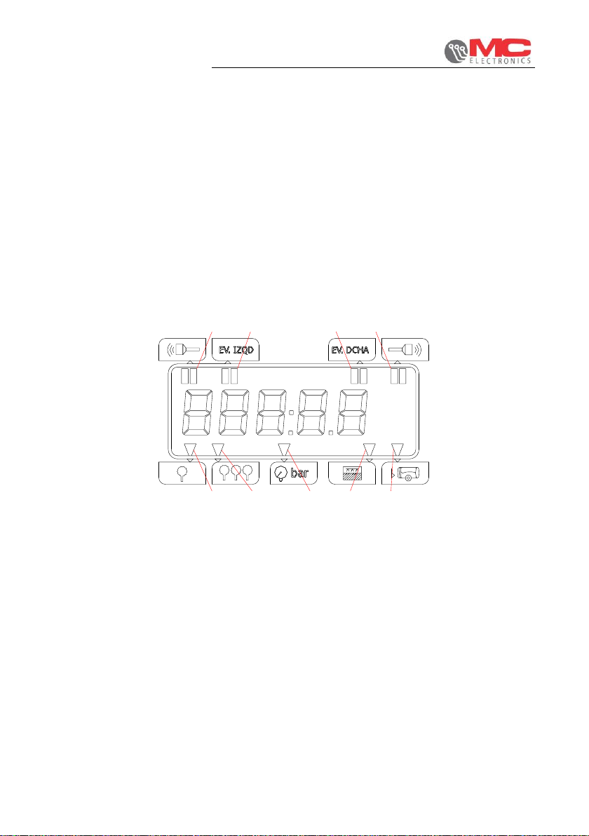
The operating status of the solenoid valves is shown on the display by two other pairs
of vertical segments (ref. O2 and O3) in the innermost part of the display.
These bars will remain on for as long as the solenoid valves will be active.
4.1.8 Working hours
The working hours appear just after the start-up test and remain on the display for a
few seconds.
The count of the working hours is activated 5 MINUTES after the first opening of one
or both solenoid valves; it is then deactivated when there are no more solenoid valve
activations for at least 5 MINUTES.
4.2 IZQD & DCHA auto/man keys
At any time, the solenoid valves can be switched (one at a time) from the automatic
operating status to the manual operating status.
Simply press one of the two special keys (ref. B and N) and the solenoid valves will
switch to the operating mode opposed to that in which they were working previously.
4.3 S.V. IZQD & DCHA start/stop keys
At any time, the solenoid valves can be stopped or restarted.
Pressing one of the two special keys (ref. D and I) will stop the corresponding solenoid
valve if it was running, or start it if it was already stopped.
N.B. If the LED included in the keys (ref. D and I) is on, this means "STOP" and the
solenoid valve must be de-energised. If the LED is off, the opposite occurs.
4.4 General S.V. auto/man key
This key (ref. G) allows the operating status of the solenoid valves to be switched from
automatic to manual mode simultaneously.
By pressing the "AUTO/MAN GENERAL" key, the operating status of the solenoid
valves will follow the progress of the LED indicator on the key itself.
That is, the green LED of the ON key (ref. G), means automatic operation of both
sections.
If, for example, the two sections were to work opposite each other, both will work in
automatic mode.

Installation and use
SOLID CONTROL MCK 2200
11
4.5 General S.V. start/stop key
This key (ref. E) allows the solenoid valves to be stopped or restarted simultaneously.
As for the previous key, also for this function, the progress of the bright LED
corresponding to the key must be considered.
If the LED is ON it means "STOP" and both solenoid valves must be de-energised. If
the LED is off, the opposite occurs.
N.B. Only the "full opt." art. 4494 MCK 2200 model has an output available for a general
valve that is activated only if both the other two solenoid valves of the sections are de-
energised. This allows the direct discharge into the tank when not working with the
sections open.
4.6 Programming
The "PROGRAMMING" section, carried out with the keys ref. H, L and M, allows the
computer to be adapted to the machine by setting some constants described in the
following paragraph.
N.B. Only in the case of the "full opt" art. 4494 MCK 2200 model and during work (out
of the programming mode), can an output be controlled by using the keys (ref. M) and
–(ref. L) to adjust the electric pressure valve.
4.6.1 Parameter programming range
Description
Range
Step
Default Value
1
Minimum detection time for solenoid valve
opening “to”
0.0 5.0
0.1
s
2.0
2
Solenoid valve closure delay from the end
of the plant detection “tC”
0.1 5.0
0.1
s
2.0
3
Amount of product reload
“L”
0 9999
1 l
1500
4
Pulse/litre constant
“i”
1.0 999.9
0.1
pul.
72.0
5
Pressure sensor signal adjustment
constant “Pr”
15 60
1
bar
60
Set the flowmeter pulses/litre indicated by the flowmeter in the constant "i".
Set the maximum value of the working range of the pressure sensor in the constant
"Pr".
If the "distributed litres" and "working pressure" data calculated by the computer are
not consistent with the real ones, they can be corrected by modifying the value of the
relevant constants.

Installation and use
SOLID CONTROL MCK 2200
12
To enter programming (preferably with the machine stopped), press the "PROG" key
ref. (H) for 3 SECONDS.
The first constant to " Minimum detection time for solenoid valve opening " will appear;
to change the value, simply press the two "+" and "-" keys ref.(M) and (L).
To switch to the display of the next constant, press the PROG key for another 3
SECONDS and so on until the last constant.
After the constant to "Minimum detection time for solenoid valve opening", the following
3 constants will appear in the following order: tC "Solenoid valve closure delay from
the end of the plant detection", i"pulses/litre" of the flowmeter sensor, L"amount of
product load" and Pr "calibration for pressure sensor".
Once programming is complete, keep pressing the PROG key for 3 SECONDS and
the new constants will be saved and you will return to the previous work configuration.
To rapidly exit the programming phase, simply hold down the PROG key ref. (H) for 5
SECONDS.
4.7 Totalisers full scale range
4.7.1 Working hours totaliser: 0 to 9999.9 (6-minute increments = 0.1 hours) can
be reset by pressing the RESET key ref. (F) for 5 seconds upon start-up.
4.7.2 Partial plants totaliser: 0 to 99999 (increments of 1) can be reset by pressing
the RESET key ref. (F) for 3 SECONDS while the number of partial plants is
shown on the display (ref. O5).
4.7.3 Total plants totaliser: 0 to 99999 (increments of 1) cannot be reset.
4.7.4 Distributed litres totaliser: 0 to 99999 (increments of 1) can be reset by
pressing the RESET key ref. (F) for 3 SECONDS while the number of
distributed litres is shown on the display (ref. O8).
4.7.5 Litres left totaliser: 0 to 99999 (decrements of 1) can be reloaded by pressing
the RESET key ref. (F) for 3 SECONDS while the number of litres left is
shown on the display (ref. O9).
4.8 Automatic mode
In automatic mode, the opening of the solenoid valves is subject to the two lateral
sonars.
Just as an example, considering just the right section, from the moment the sensor
passes in front of the plant (switching of the relative input), the count of the delay
constant to " Minimum detection time for solenoid valve opening " relative to the sensor
begins and the two "DCHO SONAR" segments light up on the display.
If the count ends with a time greater or equal to the "to" delay, the solenoid valve is
powered and allows the product to be spread on the plant itself. From the moment
when the sensor no longer detects the plant (when the two "DCHO SONAR" segments
switch off on the display), the count of the other delay constant tC "Solenoid valve
closure delay from the end of the plant detection" begins.

Installation and use
SOLID CONTROL MCK 2200
13
Once the count is complete, the power supply to the solenoid valve is disconnected
and the product output is blocked.
Each time the solenoid valve is opened, the 2 bars at the top of the SV.DCHA display
(ref. O3) will light up. These bars will remain on for as long as the opening status of the
solenoid valve lasts.
N.B. The solenoid valves are only activated if the keys ref. D, E, I are in the "START"
configuration (LED off)
The GENERAL START/STOP key (ref. E) has priority over the status of the two
sectionswhen the following is pressed:
START/STOP GEN→ON SECTIONS→ON;
START/STOP GEN→OFF SECTIONS→OFF.
The LEDs of the three keys mentioned above follow the status of the function
associated with them.
The two sections can work both in automatic mode, both in manual mode or mixed.
The automatic mode can be enabled on the two sections separately with the two
relative keys (ref. B and N). Entering the setting is indicated by the relative green LED
going on.
For the simultaneous switch of the two sections to automatic mode, the following key
will be used (ref. E): “AUTO/MAN GENERAL”.
The enabling of this setting is indicated by the relative green LED going on. This key
(ref. E) has priority over the status of the two sections when the following is pressed:
AUTO/MAN GEN→ON SECTIONS→ON
AUTO/MAN GEN→OFF SECTIONS→OFF.
The LEDs of the keys mentioned above follow the status of the function associated
with them.
The count of the total distributed litres and that of those left in the barrel is based on
the pulses coming from the flowmeter sensor, but is subject to the fact that at least one
of the two sections is active; if both sections are not active, any pulses coming from
the flowmeter will be ignored.
4.9 Manual mode
You can proceed in two ways to switch from automatic to manual mode:
1) –at any time, by pressing the "AUTO/MAN GENERAL" key (ref. E) on the
computer, the green LED of the key goes off and the computer starts to work
in manual mode with both sections.
2) –at any time, by pressing one of the two "AUTO/MAN - SV. IZQD" or
"AUTO/MAN - SV. DCHA" keys (ref. B and N) on the computer, the green
LED of the pressed key will go off and the relative solenoid valve will start to
work in manual mode.

Installation and use
SOLID CONTROL MCK 2200
14
In the second case, it is therefore that one of the two sections works in automatic mode
and the other in manual mode.
In manual mode, the sensor signal relating to the section running in manual mode is
ignored and the relative solenoid valve is continuously activated and can be switched
off or reactivated by the operator using the keys ref. D or E or I.
The count of the litres (distributed and left) and that of the plants (partial and total)
takes place in the same way as the automatic mode.
Even in this case, the key ref. G has priority over the status of the two sections when
the following is pressed:
AUTO/MAN GEN=ON → SECTIONS=ON
AUTO/MAN GEN=OFF → SECTIONS=OFF.
The LEDs of the keys mentioned above follow the status of the function
associated with them.
5. Technical features
Power supply voltage
10 - 16 Vdc
Maximum current absorption at 16 Vdc (excluding
outputs)
400 mA
Protection rating
IP 65
Operating temperature range
-20 / +70 °C
Storage temperature range
-25 / +85 °C
Resistance to mechanical vibrations
2 g random
Project reference standards
MC14982

Installation and use
SOLID CONTROL MCK 2200
15
CAUTION!!
DO NOT WASH USING A POWER WASHER
WITH PRESSURE JET
WARNING: THIS PRODUCT CONTAINS TIN AND LEAD. IT MUST
BE DISPOSED OF AT THE END OF ITS LIFE CYCLE AT THE
DESIGNATED DISPOSAL FACILITIES OR DELIVERED DIRECTLY
TO MC ELETTRONICA SRL (ITALY).
Table of contents
Other MC Electronics Desktop manuals