McAlpine Hussmann VLL726E User manual
SPECIALTY CASE FACILITY
VLL726E/VLL726BL/VLL727BL/VSS726E/VVS727E
REFRIGERATED DISPLAY CABINETS
ENHANCED
MODELS
INSTALLATION AND MAINTENANCE INSTRUCTIONS
MAN147/1
April 2013
VLL726E
VLL727BL
VSS726E
VVS727E
VLL726BL

CONTENTS
AMBIENT OPERATING CONDITIONS ………………………...................... 3
LOCATION CONDITIONS ……………………………………...........… 3
KEY OPERATION POINTS ……………………………………………… 4
RECEIVING CABINETS …………………………………….........….. 4
CABINET INSTALLATION ….............................................................. 5
JOINING CABINETS
BASE OPTIONS
KITS
ATTACHING THE FRONT BUMPER
ADJUSTING FRONT GLASS
ELECTRICAL INSTALLATION
DRAIN INSTALLATION
PRE-START CHECK LIST
CABINET OPERATION ……………………………………………... 13
LOADING LIMITS
FITTINGS AND ACCESSORIES
TEMPERATURE CHECKING
MAINTENANCE …………………………….....................… 19
CLEANING
REGULAR INSPECTION
DISPOSAL OF THE CABINET
REPLACEMENT PARTS
CABINET SECTIONAL VIEWS …………....................……………………. 21
CABINET JOINING DIAGRAMS …………………………………………..…. 26
CABINET FOOTPRINTS ……………………….........………………. 29
HAZARD ASSESSMENT …............................................................. 33

Page 3
AMBIENT OPERATING CONDITIONS
All “V” series Refrigerated Display Cabinets have been designed to operate
under the following conditions:
Class 3M1 Ambient temperature 25ºC
Relative humidity 60%
Max cross draft 0.2 m/sec
Product Temperature -1˚C to +5˚C
Class 3M0 (VVS727E Cabinet – with shelf in angled position only)
Ambient temperature 25ºC
Relative humidity 60%
Max cross draft 0.2 m/sec
Product Temperature -1˚C to +4˚C
Ambient conditions greater than those stated may result in poorer performance
of the cabinet and higher running costs.
LOCATION CONDITIONS
Cabinets should be sited so that external influences are minimized. Situations
to avoid are:
•
Air draughts from: Air conditioning,
Ventilation,
Heating outlets,
Entranceways,
•
Heat sources: Sunlight,
Spotlights,
Hot cabinets,
Concentrated external
lighting,
Non-insulated roofs and
walls,
•
Mechanical damage:
Shopping trolleys,
Forklift trucks,
Pallet jacks,
Floor polishers,
Extra protection may be required to minimize damage.
Any of these situations could prevent this cabinet from performing correctly.
NOTE: Unless specified, there should be a 100mm gap between the cabinet and
a wall. This is to allow sufficient airflow to prevent condensation

Page 4
KEY OPERATION POINTS
•
Always keep rear doors closed when not using the cabinet
•
Do not overload the cabinet with product (see loading limits pp 13~16)
•
Do not block air delivery or air return vents
•
Do not add display ice to VLL726E and VSS726E cabinets. This will cause
fan motor damage. VLL727E cabinets are designed for display ice.
•
Do not use mechanical devices or other means to accelerate the defrosting
process, other than those recommended by the manufacturer.
•
Do not use electrical appliances inside the food storage compartmentsof the
appliance, unless they are of the type recommendedby the manufacturer.
•
Always clean cabinet as described in the cleaning section of this manual and
on the cleaning instruction label on the cabinet.
•
However, if a liquid spill should occur, the spill should be cleaned as
soon as practicable. Liquids can be acetic, and if left will risk damage
to some components in the cabinet.
RECEIVING CABINETS
Cabinets will always be dispatched in good condition. Always inspect the cabinet
and packaged accessories for damage. Note any damage on the carrier’s
consignment note prior to signing.
For concealed damage that is found later, notify McAlpine Hussmann in the relevant
country within 3 working days. Any issues will be addressed and rectified as
applicable.
Australia: McAlpine Hussmann Ltd
Email: [email protected]
Ph. 1300 36 38 40
New Zealand: McAlpine Hussmann Ltd
Tauranga
Ph. 07 578 0965
NOTE: A photographic record of any damage found is required.
Also quote cabinet serial number and a brief description of the damage.
A check should also be made to ensure:
•
That all loose parts listed on the outside packaging are present and
undamaged,
•
That glass has not moved during shipment. Test any lifting glass carefully to
ensure there is no rubbing or knocking of glass that may cause future
damage. There are glass adjustment instructions in this manual
NOTE: Any shortages will follow the same procedure as concealed damage.

Page 5
CABINET INSTALLATION
JOINING CABINETS
Cabinets shall be installed level front to back and side to side to allow correct
operation of lifting glass, and allow condensate to drain freely.
There is a 150 psig Dry Nitrogen (+/- 10psig) holding charge in the evaporator
coil, please check the pressure before safely releasing the holding charge. If
Dry Nitrogen holding charge is found to be below 140 psig, please undertake
additional leak checks of the evaporator coil.
1. Always identify the highest point on the floor where the cabinets are to be
installed. Cabinets will need to be levelled from this point.
2. Mark a line on the floor that shows the position of the rear skid rail for the line-
up.
3. Position the first cabinet, level end to end and front to back. Ensure the
footbolts are adjusted (50mm nominal adjustment range) to accommodate the
highest point in the floor. All footbolts must be adjusted to the floor. This will
ensure hinged glass maintains its position over time as the cabinet settles.
4. Apply a non-hardening, flexible sealant to the end of the cabinet to ensure a
seal between the refrigerated area of the cabinet and the ambient
environment.
5. It is advisable to apply masking tape to any visible joints to be sealed later,
before butting up the adjacent cabinet.
6. Place the next cabinet as close as possible to first cabinet and set the height of
the second cabinet to roughly match the first following the procedures in steps
3, 4, and 5.
7. Push the cases together and insert joining bolts. Make any minor adjustments
to exactly align the two cabinets and tighten the joining bolts.
8. Check cabinet is level from end to end and front to back at both ends.
9. Repeat procedures until all cabinets are aligned.
10.Apply finishing sealants and any jointer items. Remove masking tape from
sealed joins. Tidying up any excess sealant.
11.Fit bumper assemblies. Detailed instructions are on the following page.
12.Check all glass gaps on lift front cabinets. Adjust as required to have a 3mm
gap between each glass. A larger gap can be closed using a wiper strip
adjacent to ends on box cabinets.
13.Fit wiper strips to the ends of box cabinets where required to close any glass
gaps. Use RTV to glue to glass
14.After all services have been installed and completed, fit coving angles and
dress panels.
15.Clean the condensate deck of any filings and rubbish that may have
accumulated during installation. These may block drains or cause rust damage
to panels over time.
16.Fit any internal panels that have been removed for installation.
17.Fit all supplied accessories. A list of separately wrapped loose items should be
on the cabinet
NOTE: The front glass may be packed loose in VSS726E and VVS727E cabinets.
NOTE: There are joining diagrams at the back of this manual.
Page 6
BASE OPTIONS
These cabinets are supplied as standard with removable base extensions. This allows
the cabinet to be sited on a plinth and stillmaintain the optimum access and working
height for the cabinet. A full set ofpanels should besupplied with each cabinet to make
this change. If theyare not included, contact McAlpine Hussmann for the required panels
and instructions.
KITS
There are also various kits to change cabinet configurations. Instructions for the fitting of
these will be supplied with each kit. Contact Hussmann for kit options and instructions.
ATTACHING THE FRONT BUMPER
IMPORTANT!
Bumper assembly securing screws must be fitted to all
bumper assemblies.
Bumper assemblies are sent unattached for transport reasons. Therefore,
securing them correctly to prevent dislodgement and possible injury is very
important.
The following instructions should be followed carefully.
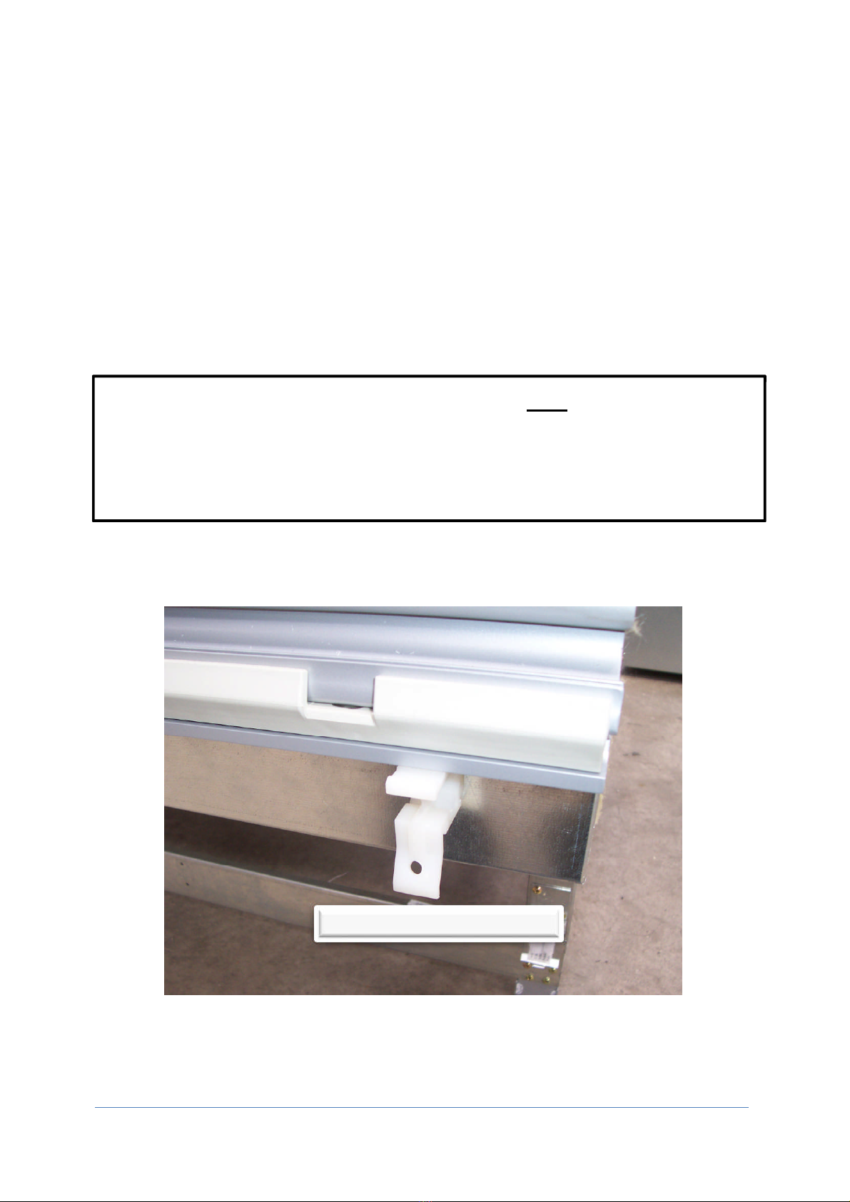
1. Unwrap the bumper assembly. You should find a pre-assembled bumper
assembly and a number of securing screws to match the number of pre-drilled
white plastic clips on the front of the cabinet.
PRE
-
DRILLED WHITE PLASTIC CLIPS

Page 7
2. Before fitting the upper colour panel (painted panel that sits at 45°), fit the
bumper assembly.
3. Align the bottom groove in the aluminium extrusion with the bottom tag on the
plastic clips.
4. Push the top of the bumper assembly on to the plastic clips.
BOTTOM GROOVE

Page 8
NOTE: If some bottom tags on the plastic clips do not sit in the extrusion
correctly they can be pushed into place once the assembly has been fitted.
This can be done using your fingers from below the assembly.
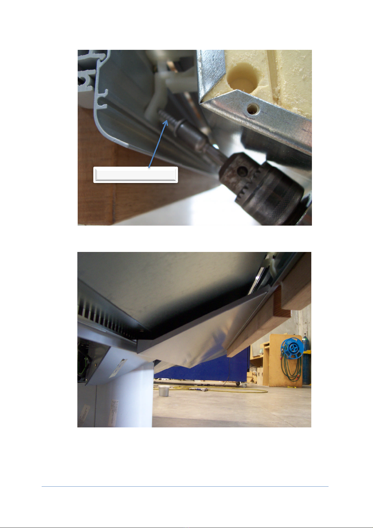
5. Pre-drill the bumper assembly aluminium extrusion at every white plastic bumper
clip with a 4.5mm drill bit, taking care not to drill through the front bumper rubber
(see insert picture for drilling depth)
4.5mm DRILL BIT
Page 9
6. Fit hex head securing screws to every white plastic bumper clip. It is advised
that the screws provided are used to ensure secure fixing
7. Front colour panels can now be fitted
USE SCREWS PROVIDED

Page 10
ADJUSTING FRONT GLASS (VLL726E ONLY)
IMPORTANT! Ensure the power to the cabinet has been disconnected before
commencing work.
Adjusting the rear posts will require the following tools:
•
Cross head screwdriver (Philips) PH2
•
Square drive screw driver S2
•
Star drive keys
•
Allen keys
•
Adjustable wrench
Adjusting the rear posts.
1. Remove the screws on the rear work top. Taking care not to damage the
trace heating wires, unhook the front of the work top and roll the back
forward to lay the work top against the canopy arms.
Screws to remove are
along the rear edge and
into each arm at
the front

Page 11
2. Loosen the grub screw on the foot of the rear post.
Front bolt
Grub screw
Rear bolt
3. Adjust the post by loosening or tightening the rear bolt. This will tilt the
post forward or backwards. You may need to slightly loosen the front bolt.
You will need to adjust all the posts on a cabinet.
4. When the posts are aligned with that of the adjacent cabinet retighten the
grub screw on the foot of the rear post.
Adjusting the glass
1. The glass can be moved laterally to even out the gaps between each piece
of glass.
2. Lift the glass to the fully open position
3. Loosen the grub screw on the locking plates at each hinge.
Hinge attachment screws
Locking plate grub screw
4. Loosen the hinge attachment screws on each hinge. This will allow the
glass clamp to be moved.
5. Tighten the hinge attachment screws on the hinges before lowering the
glass to check the new position.
6. When the new position is attained check again that the hinge attachment
screws are tight. If they are not the glass will sit at different heights and the
glass clamp extrusion could be damaged.
7. Tighten the locking plate grub screws.

Page 12
ELECTRICAL INSTALLATIONS
The electrical installation shall:
•
Meet existing regulations and safety codes,
•
Have an electrical supply to the cabinet that is independent of other supplies,
•
Be individually isolated,
There is a wiring diagram in the electric box of each cabinet.
If you require a replacement wiring diagram, please contact McAlpine Hussmann.
Please supply cabinet serial number with the request.
DRAIN INSTALLATIONS
Points to be aware of for cabinet drain installation:
•
The cabinet should be correctly leveled,
•
Water traps are factory fitted to the case,
•
The installer should ensure that the drain then slopes to the drainage point,
•
Drains may need insulating to prevent condensation dripping onto the floor,
PRE-START CHECK LIST
It is suggested that the following items be included but not limited to any pre-start
check of this cabinet.
•
All electrical connections are secure and electrical tests completed.
•
Refrigeration system has been pressure tested.
•
Drain traps have been primed with water to seal and drain screens are fitted
where provided.
•
Any loose material created during installation has been cleaned from the
cabinet. Pay particular attention to filings that may be caught under the
evaporator and fan panel seal. These could cause rust spots and pitting that
could permanently damage the stainless steel.
•
All electrical, refrigeration and sensor penetrations have been sealed inside
and outside the cabinet. Including any penetrations through baffles or other
internal panels
•
Fan panels seal correctly
Page 13
TOP OF
PRODUCT 50mm
BELOW TOP OF PRODUCT STOP
CABINET OPERATION
LOADING LIMITS
VLL726E – VLL726BL – VSS726E
These refrigerated display cabinets are not designed to cool down perishable food
products but to maintain them at the temperature which they are introduced to the
cabinet. For non-meat product this should be between -1°C and +5°C.
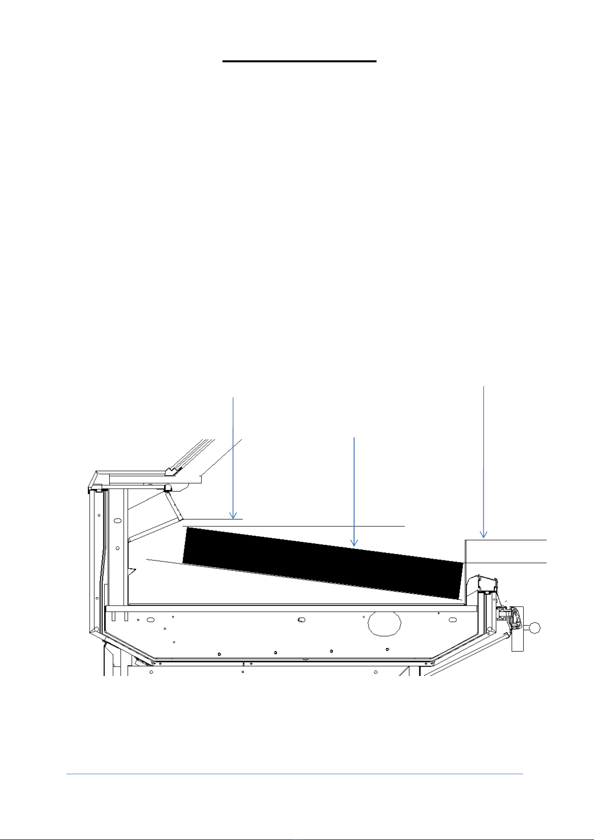
These cabinets have a load limit of 100mm above the storage surface. Product shall
be kept at least 20mm below the bottom of the air delivery vents. Food products
stored within the load limits are properly refrigerated. Food products stored outside
the load limits may not be properly refrigerated, and disturb the airflow with the result
that cabinet performance is compromisedand food products may be damaged.
VLL726E
VLL726BL
TOP OF PRODUCT
20mm
BELOW
AIR DELIVERY VENTS
100mm PRODUCT DEPTH

Page 14
VSS726E
VSS726E cabinets are available with curved or straight front glass
TOP OF
PRODUCT 20mm
BELOW
AIR DELIVERY VENTS
100mm PRODUCT
DEPTH
PRODUCT SHALL BE 50mm
BELOW PRODUCT STOP

Page 15
VLL727BL
This refrigerated display cabinet is not designed to cool down perishable food
products but to maintain the temperature at which they are introduced to the cabinet.
Ice should not be stacked more than 20mm above the Ice tray. Product should be at
least 20mm below the rear air delivery vents.
ICE LOAD LIMIT: 20mm ABOVE ICE TRAY.
PRODUCT HEIGHT LOAD LIMIT: 20mm
BELOW REAR AIR DELIVERY VENTS &
FRONT ICE STOPS.
ALWAYS FIT ICE STOPS ADJACENT TO
PATCH ENDS. THESE WILL PREVENT
CONDENSATION
20mm
20mm
20mm

Page 16
VVS727E
This refrigerated display cabinet is not designed to cool down perishable food
products but to maintain the temperature at which they are introduced to the cabinet.
This cabinet has a load limit of 100mm above the shelves and the deck rack. Food
products stored within the load limits are properly refrigerated. Food products
stored outside the load limits may not be properly refrigerated, this may disturb the
airflow with the result that cabinet performance is compromised and food products
may be damaged.
VVS727E cabinets are available with curved or straight front glass.
100mm PRODUCT DEPTH

Page 17
FITTINGS AND ACCESSORIES
Only fittings and accessories supplied with the cabinet should be used. Any
other additions may cause the cabinet to not work in its intended fashion.
VLL726E and VLL726BL fittings and accessories may include:
•
Front product stops
•
Display racks
•
Bag holders
•
Glove dispensers
•
Scale mounting frames
VSS726E fittings and accessories include:
•
Front product stops
•
Bag holders
•
Glove dispensers
VLL727BL fittings and accessories include:
•
Ice trays
•
Front ice stops.
•
Product dividers
•
Bag holders
•
Glove dispensers
•
Scale mounting frames
•
Patch end ice stops – These fit inside the ice tray adjacent to the patch end.
Bank ice against them to hold in place
It is very important that the patch end ice stops are fitted. They prevent
condensation from forming on the outside of the cabinet
VVS727E fittings and accessories include
•
Shelf fences, wire or perspex
•
Product dividers
•
Olive bar canopy kit
•
Canopy light shield*.
The canopy light shield is a standard perspex part that is sent as a loose item
to prevent transport damage. This must be fitted to protect light tubes and
help with cabinet operation.
The following are general examples of things to avoid:
•
The use of large merchandising signage inside the cabinet as these may
disturb air flow
•
Product stands that elevate product above the stated load limits
•
Manufacturer supplied ice trays turned upside down to elevate product.
•
Display decorations, product and price tickets over the air return
vents

Page 18
TEMPERATURE CHECKING
The air delivery temperature in this case should be checked at least once a
day.
The temperature should be below 1°C.
Checking should be done systematicallyand the temperature
recorded

Page 19
MAINTENANCE
CLEANING
To maximize efficiency and durability, It is suggested that your cleaning and
maintenance program include a deep clean weekly and a maintenance clean daily
•
Deep cleaning should include:
oRemoval of all food products.
oRemoval of all removable panels.
oRemove all food scraps.
oSanitizing wash.
oRinsing with clean water.
•
Maintenance clean should include:
oRemoval of all food products.
oWipe down of all exposed panels.
Do not pour water or cleaning solutions into the cabinet
oInspect for spills that may require deeper cleaning.
NOTE: if a liquid spill should occur, the spill should be cleaned as soon as
practicable. Liquids in pickled product can be particularly acetic, and if left will
risk damage to some components in the cabinet. Fresh water can be used to
dilute the liquid spill until the first opportunity for a deep clean to be carried
out.
Cleaning instructions can be found on the rear of case.
IMPORTANT! Always isolate the cabinet from the mains power supply before
deep cleaning.
For cleaning use: Warm water
Water based solutions
Soft cloths
Do not use: Abrasive products
Solvent based products
•
The front glass can be removed for cleaning (VSS726E, VVS727E).
•
Keep water away from electrical components.
•
Do not flood the tub area (below the deck display area) as electrical components
and penetration seals may be compromised causing damage and water leaks
•
Check drain traps are clear of obstructions.
oVLL727BLdrains are at the rear of the tub area.
oVSS726E,VLL726E,VLL726BLdrains are under the cover behind the
evaporator.
oVVS727Edrains are under the Evaporator fan panel. The rear deck rack
support panel will have to be removed first to allow the fan panel to be
lifted. It is important to replace the fan panel so it seals to the tub.

Page 20
Stainless steel is used inside the cabinet to give a strong corrosion resistant finish that
maximizes the cabinets service life.
It is not rustproof, particularly in the harsh environment of Food Display cabinets.
Chlorine and bromine, commonly used for sanitisation are highly caustic chemicals for
stainless steel and heat and humidity enhance the corrosiveness of these chemicals.
Regular cleaning is the best way to prevent corrosion and add to the service life for
your stainless steel product. The goal of your cleaning and maintenance program
should be to keep the stainless steel's protective chromium oxide layer intact. This is
what prevents corrosion
REGULAR INSPECTION
To ensure reliability of the cabinet and leak tightness of the refrigerant circuit, it is
advisable that trained personnel carry out periodic maintenance.
It is recommended that a check be made 3 months after commissioningof the
cabinet and then every 6 months.
The maintenance check should include:
Leak testing of the cabinet refrigerant circuit,
Ensuring no damage has occurred to any electrical components,
Cleaning the evaporator coil,
Particular attention should be given to the operation of any
safety devices.
Checking lift glass to ensure it has not moved in the glass clamp and
that it operates correctly (VLL726E, VLL726BL, VLL727BL).
Ensure front and end ice stops are in good order and being used
(VLL727BL)
Damage to cabinet components that need to be replaced to ensure
proper cabinet operation.
These checks will ensure the best possible performance of the cabinet over its
service life.
DISPOSAL OF THE CABINET
It is encouraged that the cabinet be refurbished if practical.
If disposal is necessary, please be aware that the foam-insulatedpanels incorporate
cyclo-pentane as the blowing agent and will require the cabinet to be disposed of in
accordance with local authority guidelines.
REPLACEMENT PARTS
All parts that may fail during the life of the cabinet are available from McAlpine
Hussmann.
When ordering replacement parts please quote the serial number of the
cabinet to ensure correct replacement.
This manual suits for next models
4
Table of contents


