MCCI 3141 User manual

MCCI Corporation
3520 Krums Corners Road
Ithaca, New York 14850 USA
Phone +1-607-277-1029
Fax +1-607-277-6844
www.mcci.com
Model 3141 USB4™ Switch User Manual
Engineering Report 950001601
Rev A
Date: 2021-09-01
Copyright © 2021
All Rights Reserved

Model 3141 USB4™ Switch User Manual
Engineering Report 950001601 Rev A
- ii -
PROPRIETARY NOTICE AND DISCLAIMER
Unless noted otherwise, this document and the information herein disclosed are proprietary to MCCI
Corporation, 3520 Krums Corners Road, Ithaca, New York 14850 (“MCCI”). Any person or entity to
whom this document is furnished or having possession thereof, by acceptance, assumes custody thereof
and agrees that the document is given in confidence and will not be copied or reproduced in whole or in
part, nor used or revealed to any person in any manner except to meet the purposes for which it was
delivered. Additional rights and obligations regarding this document and its contents may be defined by
a separate written agreement with MCCI, and if so, such separate written agreement shall be controlling.
The information in this document is subject to change without notice, and should not be construed as a
commitment by MCCI. Although MCCI will make every effort to inform users of substantive errors, MCCI
disclaims all liability for any loss or damage resulting from the use of this manual or any software
described herein, including without limitation contingent, special, or incidental liability.
MCCI, TrueCard, TrueTask, MCCI Catena, and MCCI USB DataPump are registered trademarks of MCCI
Corporation.
MCCI Instant RS-232, MCCI Wombat, NerveCircuit, and InstallRight Pro are trademarks of MCCI
Corporation.
All other trademarks and registered trademarks are owned by the respective holders of the trademarks
or registered trademarks.
Copyright © 2021 by MCCI Corporation.
Document Release History
Rev A
2021-09-01
Initial Release

Model 3141 USB4™ Switch User Manual
Engineering Report 950001601 Rev A
- iii -
TABLE OF CONTENTS
1 Introduction ..........................................................................................................................................5
2 Model 3141 Configuration and Setup...................................................................................................5
2.1 Model 3141 Powering up and Enumeration.................................................................................6
3 MUTT Software Package Requirements ...............................................................................................6
3.1 Model 3141 Command Line Tools ................................................................................................6
3.1.1 Using ConnExUtil.exe ............................................................................................................6
3.1.1.1 Sample Commands ...........................................................................................................7
3.1.1.1.1 Connect to a port........................................................................................................7
3.1.1.1.2 Disconnect all ports from the SUT ..............................................................................7
3.1.1.1.3 Loop sequentially connecting each port to the SUT...................................................8
4 Mode 3141 Quick Test procedure ........................................................................................................8
4.1 Model 3141 Quick Test (Windows)...............................................................................................8
4.2 Model 3141 control using Serial Commands................................................................................8
4.2.1 For Windows System.............................................................................................................8
4.2.2 For Linux Machine...............................................................................................................10
4.3 MCCI Cricket UI ...........................................................................................................................14
5 Getting Help........................................................................................................................................15
LIST OF TABLES
Table 1. Model 3141 Ports Description.........................................................................................................5
Table 2. ConnExUtil.exe Device Commands .................................................................................................6
Table 3 Serial Control Commands...............................................................................................................14
LIST OF FIGURES
Figure 1 Model 3141.....................................................................................................................................5
Figure 2 Serial Port Setup..............................................................................................................................9
Figure 3 Terminal Setup..............................................................................................................................10
Figure 4 Enumeration in Linux Machine.....................................................................................................11
Figure 5 Minicom Terminal Setup...............................................................................................................12
Figure 6 Minicom Serial Port Setup ............................................................................................................12
Figure 7 Minicom Save Setup......................................................................................................................13
Figure 8 Minicom Welcome Screen............................................................................................................13

Model 3141 USB4™ Switch User Manual
Engineering Report 950001601 Rev A
- iv -
Figure 9 MCCI Cricket UI .............................................................................................................................15
LIST OF SEQUENCE DIAGRAMS
No table of figures entries found.

Model 3141 USB4™ Switch User Manual
Engineering Report 950001601 Rev A
- 5 -
1Introduction
The MCCI® Model 3141 USB4™ Switch is a computer-controlled programmable 2:1 switch, connecting
two USB Type-® receptacles to a single Type-C plug. It is compatible with USB4 hosts and devices, as well
as older protocols such as Thunderbolt™ 3, USB 3.2, USB 2.0, USB Type-C Alternate Modes, and of
course Power Delivery.
The Model 3141 USB4 Switch automates connect/disconnect of one or two devices to a USB Type-C port.
It can be used in stress testing, switching between peripherals (for example, a dock and a display), or
any automated reconfiguration of a USB Type-C port. It is compatible with the MCCI Model 3101 /
Microsoft Type-C ConnEx Connection Exerciser tools and scripts and integrates with the tools in the
Windows Hardware Lab Kit(HLK) to support participation in the Windows Hardware Compatibility
Program.
Figure 1 Model 3141
2Model 3141 Configuration and Setup
Model 3141 has 2 Type-C connectors. The connectors and the description are provided below
Table 1. Model 3141 Ports Description
Port name
Description
Control / Power (J1)
Micro B connector is used to provide power to the Model 3141 USB4 Switch
J2
System under Test (SUT)
J3
Port 1 (Type-C receptacle)
J4
Port 2 (Type-C receptacle)

Model 3141 USB4™ Switch User Manual
Engineering Report 950001601 Rev A
- 6 -
2.1 Model 3141 Powering up and Enumeration
The Model 3141 USB4 Switch can be powered up from the USB Micro –B port (J1) on the Model 3141.
The device will be enumerated as a COM port in the Device Manager.
3MUTT Software Package Requirements
The Microsoft MUTT software package is a suite of tools used to run tests to check interoperability with
Windows.
It includes utilities to update the firmware, switch between the peripheral ports, and send requests to
simulate test cases. It also contains test driver packages that test the functionality of the buses, its
controller, and devices connected to the bus.
In order to use the Microsoft MUTT software package to control the 3141, the following requirements
must be met:
The SUT must have the Windows 10 operating system.
You must download and install the latest MUTT software package on the SUT.
Installation of the test tools requires an elevated command window.
To open an elevated command window, the user must be a member of the Administrators group on the
proxy controller. To open an elevated Command Prompt window, right click on the Start button in the
task bar, and select “Command Prompt (Admin)”.
For information about the tools, see Tools in the MUTT software package, on the Microsoft website.
Microsoft ConnEx Command Line Tools
3.1 Model 3141 Command Line Tools
The Model 3141 can be controlled using the following methods
3.1.1 Using ConnExUtil.exe
Table 2. ConnExUtil.exe Device Commands
Device Commands
/setPort p
Switch to specified port ‘p’
Connect a specific port either by number (1,2) or by
name (J3, J4). Specifying port 0 will disconnect all
ports.
/getPort
Read the current
connected port
Read the currently connected port, 1,2, zero
indicating disconnected.
/version
Read the device version
/SuperSpeedOn
Enable SuperSpeed
Enables SuperSpeed globally for current and future
connections until a /all /SuperSpeedOff command
is sent. If SuperSpeed is disabled, and port 1 or 2
is connected, this will trigger a reconnect at
SuperSpeed. SuperSpeed is enabled by default.

Model 3141 USB4™ Switch User Manual
Engineering Report 950001601 Rev A
- 7 -
Device Commands
/SuperSpeedOff
Disable SuperSpeed
Disables SuperSpeed globally for current and
future connections until a /all /SuperSpeedOn
command is sent or the device is reset. If
SuperSpeed is enabled and port 1 or 2 is
connected, this will trigger a reconnect with
SuperSpeed lines disabled.
/setDelay t
Set command delay ‘t’ in
seconds
Setting a command delay will cause the next /all
/setPort or /SuperSpeed{On/Off} command to be
delayed by ‘t’ seconds where ‘t’ ranges from 0 to
99. This is a one-time setting, only the next
command is delayed. Sending multiple commands
before the delay timer has expired is not supported.
/setDisconnectTimeout
t
Set disconnect timeout ‘t’
in milliseconds
Set a disconnect timeout for the next non-zero /all
/setPort command. On the next connect event, the
port will only remain connected for ‘t’ milliseconds
before disconnecting. This is a one-time setting,
only the next connect event will be automatically
disconnected. Allowed range is from 0 –9999 ms.
/setdata i d
Set custom data ‘d’ at
index ‘i’
Set a custom data /all /setdata command to be set
a data ‘d’ (2 decimal digit) at index ‘i’ (0-9)
/getdata i
Read custom data at index
‘i’
Read the custom data /all /getdata command to
get a data from index ‘i’ (0-9)
3.1.1.1 Sample Commands
3.1.1.1.1 Connect to a port
The following command will connect the device on port 1 to the SUT:
Connexutil.exe /all /setport 1
Alternately, you can use the port name as printed on the board. For example, to connect the device on
J3 to the SUT:
Connexutil.exe /all /setport J3
3.1.1.1.2 Disconnect all ports from the SUT
Port 0 is a special port indicating that the SUT should be disconnected. The following example shows
how this is written.
Connexutil.exe /all /setport 0

Model 3141 USB4™ Switch User Manual
Engineering Report 950001601 Rev A
- 8 -
3.1.1.1.3 Loop sequentially connecting each port to the SUT
The following code, if put in a command script, will sequentially connect each port to the SUT. At the
end of the sequence, the SUT is left connected to port 4.
for %p in (1 2) do (
connexutil.exe /all /setport %p
echo Confirm device on port %p
pause
)
4Mode 3141 Quick Test procedure
4.1 Model 3141 Quick Test (Windows)
1. Identify the COM port of your Model 3141.
2. Open an administrator cmd.exe window by right-clicking the Start button in the taskbar, and selecting
“Command Prompt (Admin)”.
3. Set the baud rate and mode of the target port using the following command. (Remember to change
“COMx” to the actual COM port identified in step 1.)
c> mode COMx baud=9600 parity=n data=8 dtr=on
4. Initialize the connection exerciser using the following command:
c> echo >\\.\COMx port 0
5. Use the following commands to enable specific ports:
CONNECTOR
COMMAND
EFFECT
J3
echo >\\.\COMx port 1
Connects the first Type C port
to the SUT
J4
echo >\\.\COMx port 2
Connects the second Type C
port to the SUT
-
echo >\\.\COMx port 0
No port is connected to the
SUT.
4.2 Model 3141 control using Serial Commands
4.2.1 For Windows System
The following instructions apply to Windows 10.
1. Plug the J2 port (Type-C receptacle) of the board to the Type-C port on the SUT.

Model 3141 USB4™ Switch User Manual
Engineering Report 950001601 Rev A
- 9 -
2. Connect the one end of the Error! Reference source not found. to the USB Connector on Model
3141 board and the other end of the cable has to be connected onto the SUT to provide power
and to control to the board.
3. Then check the Device Manager, the device will enumerate as Serial COM port device.
4. Download any terminal software and configure it. (Eg- TeraTerm)
5. Open the TeraTerm and do the following setup.
a. Tera term can be downloaded from Tera Term
b. Verified the port number from the Device Manager and set the Serial port setup and
then do the Terminal setup as mentioned in the Figure 2 & Figure 3 respectively.
6. Connect the SUT in J2 Port and connect the Peripherals in other ports of Model 3141.
7. From the terminal window, control the Model 3141 operation using the serial control
commands listed in
8. Table 3 Serial Control Commands
Figure 2 Serial Port Setup

Model 3141 USB4™ Switch User Manual
Engineering Report 950001601 Rev A
- 10 -
Figure 3 Terminal Setup
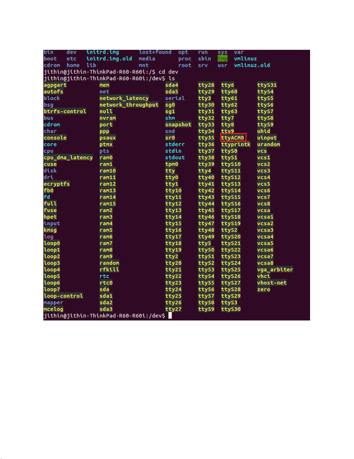
4.2.2 For Linux Machine
1. In Linux Machine, Model 3141 is enumerated as a serial port (ACM) device.It can be found
under /dev (e.g./dev /ttyACM0). Double check by plug and play the Model 3141.
Model 3141 USB4™ Switch User Manual
Engineering Report 950001601 Rev A
- 11 -
Figure 4 Enumeration in Linux Machine
2. Open that port in Minicom or any other terminal
3. To open Minicom Terminal, type sudo minicom –s
4. From this Terminal window, configure the Serial Port by select the Serial Port Setup and press
enter to continue with the setup.

Model 3141 USB4™ Switch User Manual
Engineering Report 950001601 Rev A
- 12 -
Figure 5 Minicom Terminal Setup
5. Type A to select the device and press enter.
6. Select the Baud Rate, Data bits, Parity, Stop, Flow Control according to the device connected
and press enter.
Figure 6 Minicom Serial Port Setup
7. Press enter to exit. Cursor will come to Change which setting ? –Press Enter
8. Select Save setup as dfl and press enter to save the Configuration

Model 3141 USB4™ Switch User Manual
Engineering Report 950001601 Rev A
- 13 -
Figure 7 Minicom Save Setup
9. Then select Exit and press enter to exit the configuration
10. Now port opened, Minicom welcome screen will appear as in the
11. Figure 8
Figure 8 Minicom Welcome Screen
12. Connect the SUT in J2 Port and connect the Peripherals in other ports of Model 3141.
13. From the terminal window, control the Model 3141 operation using the serial control
commands listed in
14. Table 3 Serial Control Commands

Model 3141 USB4™ Switch User Manual
Engineering Report 950001601 Rev A
- 14 -
Table 3 Serial Control Commands
Command
Usage/Example
Description
version
version
Returns board and Firmware version
port <options>
port
Returns current connected port number
port 1
Connect to USB port 1 (J3)
port 2
Connect to USB port 2 (J4)
port 0 (or other)
Disconnect all ports
Defaultport <options>
port 1
Set the default power on port to port 1
port 2
Set the default power on port to port 2
port 0
Default power on state is disconnected
delay <seconds>
delay 5
seconds to delay the port change
timeout <milliseconds>
timeout 50
next port change will disconnect after
specified number of ms
superspeed <options>
superspeed 1
Enable superspeed
superspeed 0
Disable superspeed
put <index> <value>
Stores byte value at index, where index
is less than 10
get <index>
Return byte value stored at index
status
Print useful status information
reset
Uses the GPIO line to reset the
microcontroller
4.3 MCCI Cricket UI
MCCI also developed and released a convenient and user friendly software "MCCI Cricket UI" to control
the Model 3141 USB4 Switch along with our other USB Switches and Connection Exercisers.
It is now open source and it can be downloaded from the MCCI Cricket UI

Model 3141 USB4™ Switch User Manual
Engineering Report 950001601 Rev A
- 15 -
Figure 9 MCCI Cricket UI
5Getting Help
If you have a question about using the Model 3141, please visit MCCI’s support community for the
Model 3141. Feel free to post a question! We’ll do our best to assist, and you may benefit from the
experience of others. You may also post private questions to MCCI by opening a ticket or by sending
found on the underside of the larger board. It is a hexadecimal string of the form 00-02-CC-xx-yy-zz.
Table of contents
Popular Switch manuals by other brands


Extreme Networks
Extreme Networks SSA-G8018-0652 Hardware installation guide

ATEN
ATEN Master View ACS-1712 user manual

Pepperl+Fuchs
Pepperl+Fuchs Vibracon LVL-M2C instruction manual

Linkskey
Linkskey LDV-302ARC Quick installation guide

NETGEAR
NETGEAR FS509 Specifications

Allnet
Allnet ALL-SG8910PM user manual


