MCG Surge Protection XT Series User manual

SENTINEL POWER INC
• Toll Free: 1-800-784-7989 • www.sentinelpowerinc.com • E-Mail: ken@sentinelpower.com
922 Middletown Rd, New Stanton, PA 15672, USA • Telephone: (724) 925-8181 • Fax: (724) 925-1764
1. Conrm Model with Power Service.
All wiring to be done in accordance with National Electric Code and local codes by qualied electricians.
Note: This device features internal protection that will disconnect the surge protective component at the end of its useful life
but will maintain power to the load - now unprotected. If this situation is undesirable for the application, follow the instructions
for servicing the device.
Measure Ø-N, Ø-Ø, Ø-Gnd with voltmeter to conrm application voltage prior to installation.
For best performance, mount protector as close to service panel as possible. Secure unit to mounting surface.
Use proper fasteners as indicated. (Fasteners not supplied.)
2. Disconnect Power before Installation.
3. Mounting.
MCG Surge Protection
Model 160MXT Installation Instructions
Product No. 299-600-91 Rev. B
160MXT
120T
120Y
220Y
240Y
240DCT
277Y
347Y
240D
480D
600D
Power Service
120/240 VAC
120/208 VAC
220/380 VAC
240/415 VAC
240/120/120 VAC
277/480 VAC
347/600VAC
240 VAC
480 VAC
600 VAC
Description
1 ph, 3w + gnd, split phase
3 ph, 4w + gnd, Wye
3 ph, 4w + gnd, Wye
3 ph, 4w + gnd, Wye
3 ph, 4w + gnd, High-leg Delta
3 ph, 4w + gnd, Wye
3 ph, 4w + gnd, Wye
3 ph, 3w + gnd, Delta
3 ph, 3w + gnd, Delta
3 ph, 3w + gnd. Delta
Wiring Diagram (pg. 2)
1
2
2
2
3
2
2
4
4
4
Page 1 of 8
Important Warranty Information
MCG surge protectors are designed to work at specic voltages and congurations, for example, at 120/
208VAC, wye. Installation of the surge protector improperly on a power system will automatically void
the warranty.

SENTINEL POWER INC
• Toll Free: 1-800-784-7989 • www.sentinelpowerinc.com • E-Mail: ken@sentinelpower.com
922 Middletown Rd, New Stanton, PA 15672, USA • Telephone: (724) 925-8181 • Fax: (724) 925-1764
Page 2 of 8
Surge Protector
Service
Grn Gnd
Blk
Wht Neu
G
øA øB øC
Neu
Red
L2
L1
Gnd
Single Phase
120/240VAC
Neu
Surge Protector
Grn Gnd
Blue
Blk
G
-240 DCT
(Hi-Leg)
øA øB øC
Neu
Orange
(Hi-Leg)
CBA
Gnd
Service
240/120/120VAC
Wht Neu Neu
Micro-Z Cable
Surge Protector
Grn Gnd
Blue øC
Blk øA
G
Three Phase, Delta
øA
øBøC
Red øB
CBA
Gnd
Service
240VAC
480
600
Micro-Z Cable
Micro-Z Cable
Surge Protector
Grn Gnd
Blue øC
Blk øA
G
Three Phase, Wye
øA øB øC
Neu
Red øB
CBA
Gnd
Service
120/208VAC
220/380
240/415
277/480
347/600
Wht Neu Neu
Micro-Z Cable
Fig. 1 Fig. 2
Fig. 3 Fig. 4
Hi-Leg (208VAC L-N) is connected
at øB position, but sometimes øA
or øC may be used. Measure voltage
to ensure which phase is the Hi-Leg.
Use Orange wire for Hi-Leg.
4. Wiring and Circuit Breaker Recommendations.
Cut the pre-installed 10 AWG power cable back as short as possible. Electrician Note: Use a dedicated 30A, UL489 Listed circuit
breaker to connect the protector. Circuit breaker voltage and interrupt rating must be suitable for the service.

SENTINEL POWER INC.
• Toll Free: 1-800-784-7989 • www.sentinelpowerinc.com • E-Mail: ken@sentinelpower.com
922 Middletown Rd, New Stanton, PA 15672, USA • Telephone: (724) 925-8181 • Fax: (724) 925-1764
7. Counter Trigger Sensitivity. See Diagram on Page 4.
The counter sensitivity is preset at the factory to its most sensitive position. If you are observing too many counts on the
display, you can reduce the sensitivity of the counter. Protection is not affected.
To access the counter’s sensitivity adjustment:
a. Loosen clamps and open door – DO NOT TOUCH ANYTHING – HIGH VOLTAGE PRESENT.
b. Observe circuit board mounted on back of door.
c. Locate shorting block located at top right of circuit board. Note: The shorting block is a small, black plastic
jumper that connects two points together electrically. To remove it, simply pull it straight out.
d. For the highest sensitivity, move the shorting block to the top-most position-Position 1.
e. For the lowest sensitivity, move the shorting block to the bottom-most position-Position 4.
f. Close door and secure clamps.
5. Powering up the Protector.
To prevent possible electrical hazard, door on protector MUST be closed before applying power.
Upon power up, the front panel will show the following:
a. Green PROTECTION PRESENT light should be illuminated
b. Red PROTECTION REDUCED light should be off.
c. If counter indicates a non-zero value, reset it by pressing SW2. See Step 8.
Page 3 of 8
Power
Present
6. Beeper Mute Feature. See Diagram on Page 4.
To access the mute switch:
a. Loosen clamps and open door.
DO NOT TOUCH ANYTHING – HIGH VOLTAGE PRESENT.
b. Observe circuit board mounted on back of door.
c. Locate slide switch at lower left position on circuit board marked SW1 (Audible/Mute).
d. Move switch to desired position. Switch is factory set to AUDIBLE position.
e. Close door and secure clamps.
Protection
Reduced
SW1
Most Sensitive
Least Sensitive
8. Counter Reset Feature. See Diagram on Page 4.
This feature sets the front panel event counter back to zero. The counter reset capability is generally only exercised at
time of installation, where power up may have caused and event. A monthly log is recommended to keep track of transient
occurrences.
To reset event counter:
a. Loosen clamps and open door – DO NOT TOUCH ANYTHING – HIGH VOLTAGE PRESENT.
b. Observe circuit board mounted on back of door.
c. Locate switch on bottom of board labeled SW2.
d. Press SW2 to reset counter back to zero.
e. Close door and secure clamps.
SW2

SENTINEL POWER INC.
• Toll Free: 1-800-784-7989 • www.sentinelpowerinc.com • E-Mail: ken@sentinelpower.com
922 Middletown Rd, New Stanton, PA 15672, USA • Telephone: (724) 925-8181 • Fax: (724) 925-1764
Circuit Board Located on Back of Door.
9. Remote Relay Feature. See Diagram Below.
This feature enables you to operate a remote beeper/indicator light for monitoring the surge
protector status from a remote location.
To access remote relay terminal block:
a. Loosen clamps and open door.
DO NOT TOUCH ANYTHING – HIGH VOLTAGE PRESENT.
b. Observe circuit board mounted on back of door.
c. Locate TB1 at the left bottom of the circuit board.
d. There are three terminals, each labeled NC (Normally Closed), C (Common),
and NO (Normally Open). These are 1 Form C contacts rated at 1A, 30VDC.
Maximum switched power: 30W/60VA.
e. Connect remote monitoring circuit (user supplied) to the appropriate terminals.
f. Close door and secure clamps.
Page 4 of 8
Note 1: Class 2 Wiring Only. 14-22 AWG.
Note 2: Recommended screw torque: 9 in-lbs.
SENTINEL POWER INC.
• Toll Free: 1-800-784-7989 • www.sentinelpowerinc.com • E-Mail: ken@sentinelpower.com
922 Middletown Rd, New Stanton, PA 15672, USA • Telephone: (724) 925-8181 • Fax: (724) 925-1764
Page 5 of 8
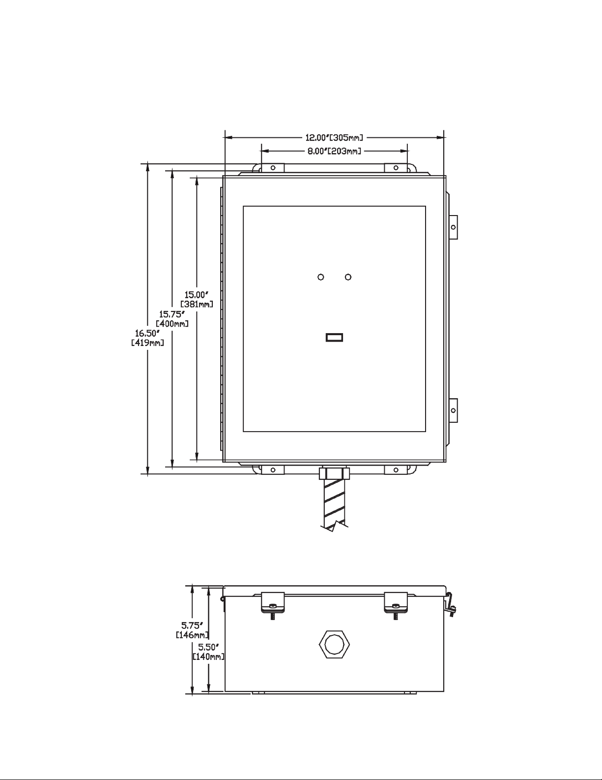
Dimensions

SENTINEL POWER INC.
• Toll Free: 1-800-784-7989 • www.sentinelpowerinc.com • E-Mail: ken@sentinelpower.com
922 Middletown Rd, New Stanton, PA 15672, USA • Telephone: (724) 925-8181 • Fax: (724) 925-1764
Page 6 of 8
Module Positions

SENTINEL POWER INC.
• Toll Free: 1-800-784-7989 • www.sentinelpowerinc.com • E-Mail: ken@sentinelpower.com
922 Middletown Rd, New Stanton, PA 15672, USA • Telephone: (724) 925-8181 • Fax: (724) 925-1764
Page 7 of 8
10. Troubleshooting and Maintenance.
MCG surge protectors do no require any periodic maintenance. However, if the red “Protection Reduced” light
is illuminated on the front panel, a fault condition exists and the beeper will sound.
When this occurs, follow the procedure below:
a. Loosen clamps and open door. WARNING: RISK OF ELECTRIC SHOCK .
DO NOT TOUCH ANYTHING. SERVICE TO BE PERFORMED BY QUALIFIED PERSONNEL.
b. Refer to diagram on page 4. Locate the four red LED’s (lights) in the middle-right position on the circuit
board on back of door. Each red LED corresponds to a protection module.
1. If the left top LED (Neutral to Ground) is on – replace the left top module.
2. If the right top LED (PHASE 2) is on – replace the right top module.
3. If the left bottom LED (PHASE 1) is on – replace the left bottom module.
4. If the right bottom LED (PHASE 3) is on – replace the right bottom module.
NOTE: Delta models do not contain a Neutral – Ground module.
c. Once you have noted which module(s) need to be replaced. REMOVE POWER FROM PROTECTOR.
d. Unplug the small, ribbon cable from the module.
e. Unscrew the three mounting bolts (use a 5/16” hex driver) located at the base of the module.
f. Make sure the replacement module is the same voltage and type as the original one. This is veried by
matching the part numbers (i.e. 169-xxx-xx).
If the numbers do not match, contact the factory at 1-800-851-1508.
g. Plug the ribbon cable in and mount module securely. Note: The ribbon cable connector is polarized so it
will only plug in one way. Push connector in rmly but do not force as the mating connector may
be damaged.
h. Close door and secure clamps.
i. Apply power by turning circuit breaker back on.
j. Observe green “Power Present” light on and red “Protection Reduced” light off.

SENTINEL POWER INC.
• Toll Free: 1-800-784-7989 • www.sentinelpowerinc.com • E-Mail: ken@sentinelpower.com
922 Middletown Rd, New Stanton, PA 15672, USA • Telephone: (724) 925-8181 • Fax: (724) 925-1764
WARNING - RISK OF ELECTRIC SHOCK
Disconnect power before servicing. Service to be performed by qualied personnel only.
Page 8 of 8
Front Panel Monitoring and Diagnostics
This manual suits for next models
1


