McIntosh MR-55 User manual

INSTRUCTIONMANUAL
MclNTOSHMODELMR-55
AM-FMTUNER
(SerialNo.1KOOOandup)
MclNTOSHLABORATORY,INC.
2ChambersSt.Binghamton,N.Y.
U.S.A.
www.eskonline.nl

TheMclntoshMR-55isa superiorqualityAM-FMTunerfor,useinhomemusicsystemsandprofes-
sionalapplicationswheredistortionfreereceptionisneeded.Typicalprofessionalusesare"offtheair"re-
cording,broadcastmonitor,rebroadcasting,etc.
Athoroughperusalofthisinstructionmanualwill givegreaterenjoymentandbetterlistening.TheMR-55
isthefinesttuneravailableandcompletefamiliaritywithitsfunctionsandoperationwillresultintheout-
standingperformanceyouexpectfroma Mclntoshproduct.
SPECIFICATIONS:
AM
Sensitivity:
1.5microvolts
Selectivity:
NarrowPosition:4 K.C.Bandwidth,± 10K.C.from
centerdown53D.B.
MediumPosition:13K.C.Bandwidth,± 10K.C.from
centerdown20D.B.
BroadPosition:20K.C.Bandwidth
(MeasurementsincludeR.F.andLF.circuits.Charac-
teristicssubstantiallyunchangedoverentireR.F.tun-
ingrange.)
A.V.C.:
Exceptionallystrong;lessthan4 D.B.audiooutput
changewithinputchangesfrom10microvoltsto
100,000microvolts.
Distortion:
Lessthan1%at100%modulation
Hum:
50D.B.belowfullsignal
Bandwidth:
LF.at600K.C.—20K.C.;at1600K.C.—20K.C.
R.F.at600K.C.—21K.C.;at1600K.C.—23K.C.
AudioBandwidth:
BroadPosition± 3 D.B.—20to10K.C.
MediumPosition± 3 D.B.—20to6.5K.C.
NarrowPosition± 3 D.B.—20to2.0K.C.
SensitivitySelector:
ThreePositions
FrontEnd:
21K.C.Constantbandwidth,bandpassinput
WhistleFilter:
70D.B.rejection10K.C.
FM
Sensitivity:
3Microvoltsat100%modulation(±*75K.C.
Dev.)forlessthan3%totalnoiseanddistortion
(BasedonI.H.F.M.(proposed)standardsfor
measuringF.M.Tuners)
CaptureRatio:
1to0.8
I.F.Amplifiers:
Four
I.F.Bandwidth:
200K.C.;FlatonTop
I.F.Transformers:
Mechanicallycaptive
Limiters:
Two;zerotimeconstantgrated-beamfollowedby
a0.5microsecondpentodelimiter
LimiterandDetectorBandwidth:
2Megacycles
FrequencyResponse:
±3 D.B.;20-20,000cycles
Hum:
75D.B.belowfullsignal
A.F.C.:
Separatedetector;strong,distortionfree,com-
pletelyvariable
Drift:
±30K.C.withoutA.F.C.:negligiblewithA.F.C.
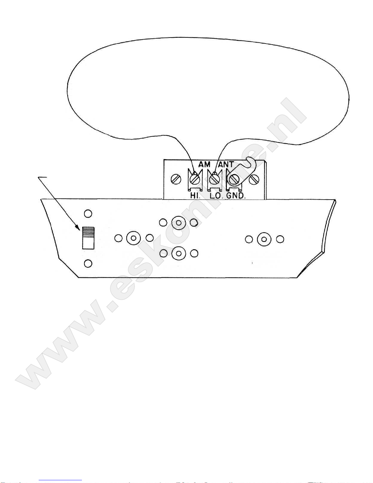
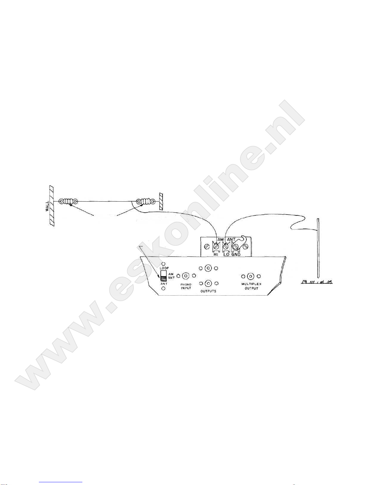
AntennaInputImpedance:
300ohmbalanced;72ohmunbalanced
Radiation:
SubstantiallybelowF.C.C.requirements
TUBE
V1—6BZ7F.M.R.F.Amplifier
V2—6BZ7F.M.ReactorandF.M.Os
V3—6AB4F.M.Mixer
V4—6BJ61stLF.Amplifier
V5—6AU62ndI.F.Amplifier
V6—6Bf63rdI.F.Amplifier
V8—6AU64thLF.Amplifier
V7—6AL5A.M.DetectorandA.V.C.Detector
V9—6AL5P.M.A.V.C.
V10—6BN61stLimiter
COMPLEMENT:
V11—6AU62ndLimiter
V12—6AL5F.M.Detector
V13—6BV8AFCDetector
V14—6BA6A.M.R.F.Amplifier
V15—6BE6A.M.Converter
V16—6AL5A.V.C.Clamper
V17—12AU7SquelchAmplifierandF.M.
Metering
V18—12AU7AudioAmplifierandCathode
Follower
SIZE:
4¾InchesHighx 14¾InchesWidex 12InchesDeep
WEIGHT:
TunerOnly:17Pounds,3 Ounces;InShippingCarton:28Pounds
—2—
www.eskonline.nl

INSTALLATIONINSTRUCTIONSFORTHE
MclNTOSHMR-55AM-FMTUNER
TheMR-55maybemountedinitsowncabinetorshelfmountedina customcabinet.Thetunerhasbeen
designedtomountona shelfratherthanhangfromthecasttunerpanel.Rubbershockmountingfeethave
beenprovidedtooffertheoptimuminmechanicalisolationfromextraneousvibrations.
Enclosedintheinstructionmanualenvelopearetwocopiesofthe"TUNERPANELCUTOUTTEM-
PLATE"andtwocopiesofthe"SHELFMOUNTINGTEMPLATE"formountingtheMR-55.Preparethe
cabinetforthemountingoftheMR-55byfirstcuttingthewoodencabinetpaneltoreceivethecasttuner
panel.
1.Onthebackofthewoodencabinetpanelmakea verticalcenterlineontheexactcenterofthearea
inwhichthetunerwillmount.Extendthiscenterlinetotheshelf.
2.Foldthe"TUNERPANELCUTOUTTEMPLATE"onthe"FOLDLINE."The"FOLDLINE"is
thelineofthetopoftheshelfonwhichthetunerwillmount.
3.Placethe"TUNERPANELCUTOUTTEMPLATE"intheproperlocationontheinsideofthecabi-
netwiththefoldlineagainsttheshelf.Thetemplatecenterlineshouldmatchthecenterlinescribedon
thepanelinstep1.
4.Inthecenterofthe"CutoutArea"onthe"TunerCutoutTemplate"arctwoholesmarked"LOCA-
TIONHOLES."Carefullyandaccuratelydrillthesetwoholeswitha 5/32inchdrill.
5.Transferthe"TUNERPANELCUTOUTTEMPLATE"tothefrontofthewoodencabinetpanel.
Matchthe"LOCATIONHOLES"fortheproperpositioningofthetemplate.Proceedwithmarkingthelo-
cationofthesixholesandtheoutlineofthecutoutonthefrontofthewoodencabinetpanel.
IMPORTANT:DRILLTHEFOUR3/16INCHANDTHETWO5/32INCHHOLESBEFORE
CUTTINGOUTTHETUNERPANELHOLE.
Thecasttunerpanelhasa 1/4inchoverlaptocovertheedgesofthecutoutincabinetpanel.
Nextpreparetheshelfformountingthetuner.
1.Measurethethicknessofthewoodencabinetpanel.
2."FOLDLINES"havebeensuppliedonthe"SHELFCUTOUTTEMPLATE"forstandardpane!
thicknessuptooneinch.Foldoncorrectfoldlineforyourwoodenpanelthickness.
4.Placethefoldededgeofthetemplateagainstthebackofthefrontpanel.Thetemplatecenterline
mustmatchthecenterlineextendedtotheshelfinstep#1ofthefrontpanelcutoutinstructions.
5.Carefullymarkthelocationsofthefour1/4inchholesandthe8 by101/4inches,ventillationhole.
6.Drillandcutouttheshelf.
NextpreparetheMR-55formountinginthecabinetbyremovingthepressedwoodshippingpalletfrom
thebottomofthetuner.
Removetheknobsbygentlypullingthemtowardyou.Removethefeltwashers.
Thecasttunerpanelhasbeenattachedtothetunerbytwoanglebracketsthatareforshippingpur-
posesonly.Theseareremovedbyunscrewingthefourscrews(twooneachside)thatholdtheanglebrackets
tothetunerchassis.Afterremovingthesefourscrewsthetunerpanelcanbeslippedoffovertheknobshafts.
Afterremovingthetunerpanellayitfacedownona protectedsurfaceforthefollowingoperations.
Removethefour6/32screws(oneoneachcorner)thatholdthetwoshippingbracketstothetunerpanel
—3—
www.eskonline.nl

REMOVE
4-6/32
SCREWS
TWOEACHSIDE"
REMOVE
4-6/32
SCREWS
"ONEEACHCORNER"
Inthepartsbagaresix6/32x 1 1/4inchesthreadedrods.Installtheseinthesixdrilledandtappedholes
inthebackofthetunerpanel.
—4—
www.eskonline.nl

PUTIN
6-6/32
THREADED
RODS
Thetunerpanelisnowreadytoheattachedtothecabinet.Thesixthreadedrodsareinsertedthrough
thetwo5/32inchandthefour3/16inchholesinthecabinetpanel.Securethetunerpaneltothecabinet
panelbyinstallingontherodsthe6/32"KEP"nutssuppliedinthepartsbag.Bringthenutsuptightwitha
wrenchornutdriver.
Thetunercannowbeinstalledinthecabinet.Thetunerissecuredtothecabinetshelfbytheinsertion
ofthefour10/32x 3/4inchthumbscrewssuppliedinthe-partsbagthroughthe1/4inchholes,intheshelf.
IMPORTANT:MAKESURETHATTHEINNERCHASSISFLOATSONTHERUBBERSHOCK
MOUNTINGFEET,ANDDOESNOTCONTACTTHECABINETORTUNERPANEL.
Nextreplacethefeltwashersandknobs.
Adequateventilationisessentialtothestableoperationofanytuner.Donotputa solidbackonthe
cabinetbehindthetuner.Ifthetunerismountedverticallymakesuresufficientventilationissupplied.
InstallationintheL-55cabinetisdonebythesameprocedureasforinstallationina customcabinet.
Thecabinetsaresuppliedwiththecutoutsandholesallprepared.
CONNECTINGPROCEDURE
FMANTENNA:Inhighsignalstrengthareasa minimumantenna,suchasthefoldeddipolesupplied,is
allthatisneededforlocal reception.Somecareshouldbeusedinlocatingthefoldeddipoleina positionthat
isfreeaspossiblefromlocalnoisesourcesandshieldingsuchasmetalroofingandbuildingframework.The
dipoleshouldbemountedhorizontally,andat90°tothelineofsightpathtothetransmittingstations.
Infringeareasa goodantennaisrequired.A highlydirectionalbroadbandantennausedinconjunction
witha rotorwillresultinsuperiorperformanceinlowsignalstrengthareas.
—5—
www.eskonline.nl

FM.
TO
300ohm
FM
ANT.
AsubstituteforthefoldeddipolecanbeanexistingVHFT.V.antenna.TheMR-55issuppliedwith
aninternalswitchingarrangementthateliminatestheneedfortwosetcouplers.TheVHFT.V.antenna
lead-inisconnectedtotheantennaterminalsmarked"FM.ANT'."Connecttheterminalsmarked"TOT.V.
SET"totheantennaterminalsontheT.V.receiverwith300ohmantennalead.WhentheMR-55selector
switchisincitherofthe"FM"positionstheantennaisdisconnectedautomaticallyfromtheT.V.receiver.
InanyotherpositionoftheselectorswitchtheantennaisconnectedtotheT.V.setanddisconnectedfrom
thetuner.
TO300ohmVHFTV.
ANT.
TO
T.V.
SET
—6—
www.eskonline.nl

75OHMUNBALANCED
ANTENNAINPUT
75OHMANTENNA:TheMR-55hasprovisionfortheconnectionofa 75ohmunbalancedantenna.
The75ohmterminalscrewsarenexttothechassisonthebackofthebrownbakelitebaluncardlocated
approximately2 inchesbehindthetuningknobflywheel.Thecenterconductorofthe75ohmcoaxiallead
isattachedtothescrewterminallocated3/8inchabovethechassis.Theouterconductororgroundsideis
connectedtothescrewterminallocatedclosetothechassis.Solderlessspadelugsaresuppliedforyourcon-
venience.
—7—
www.eskonline.nl

ANT.SWITCHIN
THISPOSITION.
10'LOOPANTENNA
A.M.ANTENNA:FacilitiesaresuppliedontheMR-55fortheuseofa lowimpedanceloopantennaor
ahighimpedancelongwireantenna.AMreceptionwillgenerallybeimprovedthroughtheuseofa properly
installedlongwireoutsideantenna.
Forlocationswhereanoutsideantennaisimpossibleorimpracticala 10footloopantennaissupplied.The
loopisattachedbetweentheterminalsmarked"HI"and"LO"onthe"AM.ANT"terminalstrip.The"AM.
ANT"terminatingswitch,locatedleftofcenternexttothephonoinputjackonthebackpanelofthetuner,
mustbeintheloopposition.
Orientationoftheloopiscritical.Itshouldbemountedinaslargea circleaspracticalinthevertical
plane.
—8—
OUTPUTS
PHONO
INPUT
AM
ANT
ANT
LOOP
MULTIPLEX
OUTPUT
www.eskonline.nl

AnoutsideAMantennaisa wireaslongaspractical,mountedashighaspossibleabovetheground,at
rightanglestopowerlines.TheleadinshouldbecarefullypositionedawayfromallA.C.lines,
The"ANTENNA"terminatingswitchmustbein"ANT"positionwhenusingoutsideorlongwire
antenna.
AgoodgroundcanbeofassistanceinAMreception.A goodgroundisdescribedasa 1/2inchrod6 to8
feetlongdrivenintotheearth.Thegroundwireisconnectedtotheterminalmarked"LO."
TOLONGWIREASHIGH
ABOVEGROUNDASPOSSIBLE
Ifthetunerisconnectedtoanoutsidegroundasdescribedabovedonotconnectanyoftheotherequip-
menttothesamegroundtopreventgroundloops.Groundloopscancauseanincreaseinhum.
Foranalternategroundforusewhenusinga longwireantennaconnecttheshortinglinkbetweentermi-
nalsmarked"LO"and"GND."
-9—
INSULATOR
ANTENNAWIRE
ANT.SWITCHIN
THISPOSITION
AM
TOGROUNDSUCHAS
8'RODINEARTH.
www.eskonline.nl

TOLONGWIREANTENNA.
ANT.SWITCHIN
THISPOSITION.
OUTPUT:Twopinjacksaresuppliedonthebackpanelmarked"Output."Thesejacksareinparallel.
Theoutputisunbalancedlowimpedance.Interconnectbetweeneitherofthesejacksandthetunerinputof
yourpreamplifierbymeansofthe6 footshieldedcablesuppliedwithyourtuner.
PlugtheA.C.cablefromthetunerintooneoftheauxiliaryA.C.outletsonthebackofthepreampli-
fier.
—10—
LOOP
AM
ANT
ANT
PHONO
INPUT
OUTPUTS
MULTIPLEX
OUTPUT
www.eskonline.nl

TheA.C.cablefromtheamplifiercanbepluggedintotheauxiliaryA.C.outletsuppliedonthebackof
theMR-55.ThisoutletiscontrolledbytheA.C.switchonthefrontofthetuner.
SEEANTENNAINSTALLATION
INSTRUCTIONS
—11—
www.eskonline.nl

MultiplexOutput
TheoutputonthebackoftheMR-55marked"MULTIPLEXOUTPUT"isanunfilteredoutputfor
feedinga multiplexadapter.
OPERATION
Theselectorswitchisa sixpositionswitchthathasthefollowingidentifications:(1)F.M.LISTEN,
(2)F.M.TUNE,(3)A.M.BRD.(4)A.M.MED.,(5)A.M.SHARP,(6)PHONO.
Phono
Theinputsensitivityis0.25volts,suitablefora crystalorceramictypephonocartridge,a magneticcart-
ridgewitha onetubepreamplifier,ortheoutputofa taperecorder.
A.M.Sharp
Theaudioresponseofthispositionislimitedto20cyclesto2000cycles.Inthe"A.M.SHARP"position
distantstationscanbereceivedwithmaximumclarityandminimumnoise.Tunetoa peakonthesignal
strengthorrightmeter.TheleftmeterorcenterofchannelmeterisonlyinuseonF.M.
A.M.
Med.
TheaudioresponseoftheA.M.MED.positionislimitedto20cyclesto6500cycles.Thispositionis
lessselectiveonnoisethanthe"SHARP"position.
A.M.
Brd.
Theunrestrictedaudioresponseis20to10,000cyclesformaximumA.M.fidelityonstronglocalsta-
tionswherenoiseisnota problem.Tunetoa dipbetweentwopeaksonthesignalstrengthmeter,orthe
loudestsound.
WhistleFilter
InallA.M.positionsthereisa 70DBrejectionofthe10K.Cwhistle.
F.M.Tune
Automaticfrequencycontrol(A.F.C.)isdisabledandULTRASONICMUTINGisaddedformaxi-
mumaccuracyandeaseintuning.Ultrasonicmutingeliminatestheannoyingnoisebetweenstations.Intun-
ingacrossthebandtakenoticeofthecompleteabsenceofnoiseevenwhenapproachinga station.
Somestationsarereceivedwithinsufficientsignalstrengthtocompletelyeliminatebackground"noise.The
ultrasonicmutingcircuithasbeensodesignedtopermitonlylistenablesignalsthrough.Signalswithannoy-
ingbackgroundnoisewillbemuted.Themeterswillfunctionnormallyandindicatethepresenceofa sta-
tion.Ifa desiredstationisnotheard,tunebymeterandchangetheselectorswitchto"F.M.LISTEN."The
stationcanthenbeheard.UltrasonicmutingisanexclusiveMclntoshdevelopmentandfeature.
Ifanantennawitha rotorisusedthesignalstrengthmetercanbeofassistanceindeterminingthe
properdirectiontopointtheantenna.Rotatetheantennauntilmaximumsignalstrengthisregisteredonthe
meter.Thebestsignaltonoiseratiousuallywillresultathighestindicatedsignalstrength.
F.M.Listen
TheultrasonicmutingcircuitisdefeatedandA.F.C.addedforgreatestlisteningpleasure.Mclntosh
A.F.C.doesnotchangeinanyrespectthelowdistortioncharacteristicsoftheMR-55.
Volume
Thevolumecontrolhasatitsextremecounter-clockwiserotationtheA.C.on-offswitch.Theswitch
alsocontrolstheA.C.availableattheauxiliaryA.C.outletonthebackofthetuner.Normaloperationfor
the"VOLUME"controlistotallyclockwise.
A.M.Sensitivity
TheA.M.sensitivityisthegreatestattheclockwisepositionoftheswitch,thecenterpositionisinter-
mediatesensitivity,andthecounter-clockwisepositionisminimumsensitivity.
Theclockwiseormaximumsensitivitypositionwilldeliverthegreatestnumberofstations.Longdistant
receptionwillbebestinthisposition.Whenselectinglocal stationsbetweenstationnoisecanbereducedby
usingeithertheminimumorintermediatesensitivitypositionswhicheverismostsatisfactoryforyourlocation.
—12—
www.eskonline.nl

A.F.C.
TheA.F.C.iscompletelyvariablefromoffatthecounter-clockwisepositionofthecontroltofullonat
theextremeclockwiseendofitsrotation.Inareaswhereweakstationsarenearstrongstationsonthedial
onlyenoughA.F.C.needbeusedtoholdtheweakstation.Nochangeinaudioqualitywillbedetected
overthecompleterotationoftheA.F.C.control.
Dial
InadditiontotheregularA.M.andF.M.identificationonthediala loggingscalehasbeensupplied
tofacilitaterepeattuningoffamiliarstations.
SERVICEINFORMATION
AllMclntoshequipmentisdesignedforlongtroublefreeoperation.Allcomponentsareofhighestqual-
ityandareconservativelyoperated.Iftroubledevelopstheequipmentmaybeservicedbyyourfranchised
dealer,a competentserviceman,orreturnedtothefactory.Equipmentwillnotbeacceptedatthefactory
unlessfactoryreturnauthorizationisfirstreceived.
Completestepbystepalignmentproceduresareoutlinedinthismanual.TheMR-55isa professionalde-
vicedependentforitssuperiorperformanceoncriticalandproperadjustment.Adjustmentsshouldbemade
onlybythoroughlyqualifiedpersonnel,andwiththeproperequipment.Theminimumrecommendedequip-
mentsareasfollows:
1.LowdistortionFM-AMSweepgenerator,suchasBoonton202E.
2.LowdistortionAMSignalgeneratorsuchasMeasurements65B.
3.UnivertersuchasBoonton207E.
4.DistortionanalyzersuchasHewlettPackard330B.
5.OscilloscopesuchasDumont274A.
6.VacuumtubeVoltmetersuchasR.C.A.WV-98A.
Muchresearchhasbeendoneinourlaboratorytoovercometheneedforalignmentandadjustmenten-
counteredinhighqualitytuners.Designparametershavebeenselectedsothatmajorchangescanoccurin
componentswithoutdegradingthehighqualityresults.Tubereplacementsseldomrequirere-alignment.Trans-
formershavebeenmademechanicallycaptivetopreventmisalignmentduetovibrationandshock.There-
fore,theneedforadjustmentandalignmenthasbeensubstantiallyreduced.MclntoshLaboratory,ofcourse,
willalignandadjustanytuneruponrequest.
GUARANTEE
Weguaranteetheperformanceofthisequipmentandthemechanicalandelectricalworkmanshiptobe
freeofseriousdefectsfora periodof90days.Thisguaranteedoesnotextendtocomponentsdamagedbyim-
properusenordoesitextendtotransportationtoandfromthefactory.
MclNTOSHLABORATORY,INC.
2ChambersStreet
Binghamton,N.Y.,U.S.A.
InCanada:ManufacturedUnderLicensebyMcCurdyRadioIndustries,Ltd.
22 FrontStreetWest,Toronto,Canada
—13—
www.eskonline.nl

FM
—
Generator
CW—
Oscillator
98MC—75
KC
50cps90MC-
CW-Oscillator
Preferably
Battery
Operated.
With
Generator
Setthe
Level
at
98MC
Increase
Over,
all
Gain
With
ExternalAmplifier
If
Necessary.Then
With
CW-Oscillator
at
90MC.
MeasureHum.Then
Switch
to
Phono
and
Measure
Hum
With
Phono
Input
Shorted
With
1Mohm.
MeasureDistortion.
Listen
88-98-108MC.
75KC.
Deviation
400cps.
DecreaseFM-GeneratorOutput
for3%
Distortion.
Reading
of
Generator
Then
Is
Measure
of
Overall
Sen-
sitivity.
Increase
Generator
Output
Until
1
Div.
or
Sensitivity
Meter
Is
Reached.GeneratorOutputReading
Nowis
Measure
of
Gain
inRFandIF
Stages.
Tune/Listen
FM
—
Generator
98MC
75KC.
Deviation
400cps.AFC-Conrrol
Fully
ClockwiseDistortionAnalyser
Audio
Output
R81and
Upper
Slug
ofT12for
Center
of
FM-Meter
Vary
Tuning
Knob
Until
FM-Meter
Remains
Stationary.
For
Tune
and
Listen
Positions
With
R81,BringFM-Meter
to
Center,
With
Selector
Switch
in
Tune
Position.
Decrease
OutputFM-Generator
Until
3%
Distortion
and
Noise
Is
Found.Then
in
Listen
Position,Adjust
T12
for
Minimum
Distortion
and
Noise.
Overall
Tune
FM
—
Generator
CenterFreq's.
88—
108MC.
75KC.
Deviation
50cps.
ThruBalun
to
Antenna
Input,
or
75ohm
Input
With
Termi-
nating
Resistors
Oscilloscope,Synchronized
to
InputSweepTestPoint
T3>
Upper
and
Lower
Slugs
T5> for
Best
Response
Curve
Vary
Freq.
From
88to
108MC.
and
Follow
With
Tuner,
for
Gesf
Response
Curve
OverFM-Band.
Give
Special
Attention
to
96.3MC
for
Interference
of9 x
10.7MC.
IF-Strip
Tune
CW
—Oscillator
10.7MC.
Point
(R)
(Pin6-V3)
Oscillator
Coupled
to(H)
Thru
.0!MF
Condenser
and
Terminating
-Resistance.
V.T.V.M.
Test
Point
T2
T3
Upper
and
lower
Slugs
T5for
Maximum
T7
T9
DefeatAVC-Action
at
Point
J
(R36-R38)
Load
Transformer-Winding
No!
UnderAdjustment
—
with
10Kohm
Resistor
Front-End
Tune
SWEEP
GENERATOR
CW—
Oscillator
CenterFreq's.
88—
108MC.
90and
105MC.
ThruBalun
to
Antenna
input
or
75ohm
input
With
Termi-
nating
Resistors
Any
Suitable
Injeclion-
Point
ToBe
Used
as90—
105MC,
MarkerPoints
Oscilloscope,Synchronised
to
Input
Sweep
FM-Tuning
Meter
Point(G)
(Pin
7-V3
)
L9— C18— L10—
C19:
For
Best
Response,
Keeping90—105MC.
Markers
in
Corres-
pondence
With
the90—
I05MC.
Dial
Points
L11—
C23:
For
Calibrating
the
Tuner
FM-
Local-Oscillator
to90—
105MC.
Dial
Points
Adjustments
of
LP-C18-L10-C19
and
L11-C23
Are
Inter
Related,
ThereforeBoth
Series
of
Adjustments
Should
Be
Checked
and
Rechecked.
Disable
the
OscillatorWhenAdjusting
L9-C18-L10-C19
Point
(E)
(Pin
5-T12)
T12:
Lower
Slug
for
Man.
R81 : For
FM-Tuning-
Meter
Center
TI2:
For
FM-Tuning-MeierCenter
Ground
Point
F (
High
SideR82)
10.7MC
Point
(C)
(Pin
7-V12]
Point
(D)
(R70-C88)
T11:
Lower
Slug
for
Max.
Upper
Slug
for
Zero
10.4MC.
T10:
Upper
Slug
for
Max.
LowerSlug
for
Max.LoadPrimary
With
1.5Kohm
Resistor
LoadSecondary
with
1.5Kohm
Resistor
Limiters,
Detector
and
Audio
Tune
CW—
Oscillator
10.7MC.
Point
(A)
(Pin
5—V9)
OscillatorCoupled
to(A)
Thru
.01MF
Condenser
and
Terminating
Resistor,
V.T.V.M.
Point
(B)
(Pin1-V11)R63:
For
Max.
100Kohm
Resistor
in
Series
With
D.C.Probe
of
V.T.V.M.
CIRCUIT
UNDER
TEST
POSITION
OF
SELSW.
SIGNAL
GENERATOR
FREQUENCY
AT
SIGNAL-SOURCE
REMARKS
MEASURED
WITH
AT
ADJUST
SIGNAL-OUTPUT
REMARKS
F.M.
www.eskonline.nl

REMARKS
SIGNAL-OUTPUT
ADJUST
AT
MEASURED
WITH
REMARKS
SIGNAL-SOURCE
AT
FREQUENCY
SIGNAL
GENERATOR
POSITION
OF
SEL.
SW.
CIRCUIT
UNDER
TEST
Load
T14
With
1.5Kohm
Resistance
Load
T13
With
1.5Kohm
Resistance
T13:
For
Max.
at
600KC.
T14:ForMax.at600KC.
Load
C94
With
1.5Kohm
Resistance
LoadC92With1.5Kohm
Resistance
C92:
ForMax.at
1500KC.
C94:
ForMax.at1500KC.
Point
(K)
(Pin
7-V15)
V.TV.M.—CrystalProbe
AntennaSwitch
at
Ant.
OscillatorCoupled
to
Antenna
Terminals
Thru
50µF
Condenser
Sensitivity
Switch
at
Max.
Pull
OutV15
Antenna
Terminals
600KC,
1500KC.
C.W,Oscillator
Broad
Front
End
to
Local
Oscillator
TI6>
T4>
Upper
and
lower
Slugs
for
Max.
T6>
Point
(L)
(R34-C134)
load
Winding
Not
Under
Adjustment
With
1Kohm
Re-
sistance.
Ground
Pin
2-T8.
T8:
Upper
and
lower
Slug
for
Max.
Point
(N)
(Pin
2-V7B)
V.T.V.M.—
D.C.Probe
Antenna
Switch
at
Ant.
Oscillator
Coupled
to
Point
(K)
Thru
.01
Condenser
Sens.
Switch
at
Min.
ReplaceV15
Point
(K)
(Pin
7-V15]
455KC.
C.W.
Oscillator
Narrow
IF-Strip
and
AVC
T15:
For
Max.
at600KC.
C102-
For
Max.
at
1500KC.
Point(L)
(R34-C134)
Antenna
Switch
at
Ant.
Oscillator
Coupled
to
AntennaTerminals
Thru
50µFCondenser
Sens.
Switch
at
Max.
Antenna
Terminals
600KC.
1500KC.
Narrow
Local
Oscillator
Adjust
T15at
LowerFreq's.
and
C102
atthe
Higher
Freq's.
T15,C102:For
Optimum
Tracking
Oscilloscope
Sens.
Switch
at
Min.
Ail
Broadcast-
BandFreq's.
±15KC.
SweepOscillator
Broad
Overall
Determine
the
Percentage
of
Modulation
Needed
to
BringAbout10DB.
Increase
in
Audio
Output
Sensitivity
is
Adequate
If
ModulationRequired
Is
less
Than
50%
AudioOutput
AudioVoltmeter
Sens.
Switch
at
Max.
GeneratorOutput10µV
600—
1500KC.
400cps.
at30%
Modulation
ModulatedGenerator
Narrow
Readings
of
AudioVoltmeter.
For
GeneratorOutputs
of:
10µV-100µV-1KµV.10KµV-100KµV
Isa
Measure
of
AVC-Control
Generator
Output
Variable
Any
Freq.
in
B.C.
3and
Modulation
400cps.
at.30%
AVC-Control
Generator
Modulated
With
400cps.Tune
in
Narrow.
Then,
in
BroadPositionIncrease
Modulating
Freg.
Till
Audio
Voltmeter
Reads
3 CLB
Down.
Modulating
Freq..
Then
Isa
Measure
of
Fidelity.
GeneratorOutput10KµV
600—1000—
1400KC.
30%
Modulation
GeneratorModulated
With
Variable
Ex-
ternal
Source
Narrow
Broad
Overall,
Fidelity
Test
MeasureDistortion.
Remove
Modulation
and
Measure
Noise.
DistortionAnalyzer
1000KC.
Modulation.
400cps.
at
100%
Modulated
Generator
Narrow
AM
www.eskonline.nl

F.M.(cont.)
Overall
TuneFM-Generalor
98MC.
75KC.
Deviation
400cps.
D.C
Voltmeter
Pin
2-V16BTune
Inand
Remove
Generator
Note
SquelchVolts
Developed
on
Noise
Only
Overall
Listen
FM-Generator
93MC,
75KC
Deviation
Thru
Balun
to
Antenna
Input
or
75ohm
Input
With
Termi-
nating
Resistors
Modulate
With
VariableExternal
Source
Audio
VoltmeterAudio
Output
Determine
Modulating
Freq's.
at
Which
Audio
Output
Drops
3DB
With
AFConandoff
CIRCUIT
UNDER
TEST
POSITION
OF
SEL.
SW.
SIGNAL
GENERATOR
FREQUENCY
'
AT
SIGNAL-SOURCE
REMARKS
MEASUREDWITH
AT
ADJUST
SIGNAL-OUTPUT
REMARKS
www.eskonline.nl

www.eskonline.nl

043-409
www.eskonline.nl
Table of contents
Other McIntosh Car Receiver manuals
Popular Car Receiver manuals by other brands

Audiovox
Audiovox HD5212 Installation and operation manual

Sony
Sony HCD-MDX10 - Compact Disk Deck Receiver... Service manual

Boss Audio Systems
Boss Audio Systems DVD-4400T user manual

JVC
JVC KD-AR765S instruction manual

Onkyo
Onkyo T-4555 - Radio Tuner Service manual

Metra Electronics
Metra Electronics 99-6544B installation instructions