McIntosh MX150 User manual

McIntosh Laboratory, Inc. 2 Chambers Street Binghamton, New York 13903-2699 Phone: 607-723-3512 www.mcintoshlabs.com
MX150 Auxiliary Output Guide
Manufactured under license from Lyngdorf Audio
A/S. ROOMPERFECT is a registered trademark and
the ROOMPERFECT logo is a trademark of Lyn-
gdorf Audio A/S. (C) Lyngdorf Audio A/S 2009.

2
2
The following connection instructions and illustra-
tion on the next page are a supplement to the MX150
Zone A Output Connection instructions on page 11
of the Owner’s Manual and the separate folded sheet
“Mc2B” Diagram. It is an example of a typical Home
Theater System. Your system may vary from this,
however the actual components would be connected in
a similar manner. For additional information refer to
“Connector and Cable Information” on page 5 of the
MX150 Owner’s Manual.
Power Control Connections:
1. Connect a Control Cable from the MX150 ZA PC
(Power Control) OUT Jack to the Power Control In
on Zone A Power Amplifier One.
2. Connect a Control Cable from Zone A Power Am-
plifier One Power Control Out to Zone A Power
Amplifier Two Power Control In Jack.
Perform additional Power Control Connections start-
ing with step 3 on page 11 of the MX150 Owner’s
Manual.
Analog Audio Connections:
3. Connect Balanced Audio Cables from the MX150
Zone A - L (Front Left Channel) and R (Front
Right Channel) to Zone A Power Amplifier One
(High Frequencies) Inputs 1 and 3 respectively.
Note: Unbalanced Audio Connections may be used
in place of the Balanced Connections.
4. Connect Balanced Audio Cables from the MX150
Zone A - AUX 1 (Left Front Channel) and AUX
2 (Right Front Channel) to Zone A Power Ampli-
fier Two (Low Frequencies) Inputs Left and Right
respectively.
Perform additional Analog Audio Connections for
the remaining channels, HDMI Connections and AC
Power Cords by refering to steps (6 thru 11) on page
11 of the MX150 Owner’s Manual.
Introduction
The MX150 offers additional Zone A Left Front Chan-
nel and Right Front Channel Outputs, two balanced
outputs and two unbalanced outputs. These Auxiliary
Outputs (1 thru 4) may be used for additional sub-
woofer outputs or for using the MX150 built-in elec-
tronic crossover circuitry. In this guide, the example
will illustrate connections along with Setup Mode
Settings for using the MX150 Electronic Crossover
Circuitry.
Almost all Loudspeakers incorporate acoustic
drivers and a passive crossover network. The passive
crossover network channels the various audio frequen-
cies to the appropriate acoustic driver taking into
account the amplitude and phases of the audio signals
the Loudspeaker reproduces. When an electronic
crossover circuitry in the MX150 is used together with
multiple Power Amplifiers and Loudspeakers, it is
very important to maintain the correct amplitude and
phases of the audio signals for accurate sound repro-
duction.
McIntosh’s Acoustics Laboratory has measured
McIntosh Loudspeakers (with separate Low Frequen-
cy/High Frequency connections) when used with the
MX150 and has arrived at the optimum settings. There
are two different settings. The first setting is for use
with McIntosh Loudspeakers with a Low Frequency
(Woofer) to High Frequency (Midrange/Tweeter)
crossover frequency of 250Hz. The second setting is
when the McIntosh Loudspeaker has a crossover of
80Hz. It is suggested to use these settings.
When the MX150 is used with non-McIntosh
Loudspeakers it is highly recommended to con-
tact your Dealer for assistance. Your Dealer has the
necessary measurement equipment and knowledge to
properly set up the electronic crossover in the MX150
for your Loudspeakers.
Connecting the MX150 when using the
Electronic Crossover

3
MX150 Auxiliary Output Guide
F15AH 125V
Note: Refer to the MX150 Owner’s Manual pages 10 and 11 for additional
connection information.
Connection Legend:
Power Control Cable* - AC Power Cords -
Audio Signal Cable -
* 2 conductor shielded with 1/8 inch stereo mini phone plug on each end.
Zone A - Power Amplifier One
High Frequencies
Left Front and Right Front Channels; Center Channel
MX150 (Partial View)
Zone A - Power Amplifier Two
Low Frequencies
Left Front and Right Front Channels
Connect to
AC Outlet
Connect to the next Power
Amplifier, Power Control IN

4
Output Settings
Operation and Installer Menu:
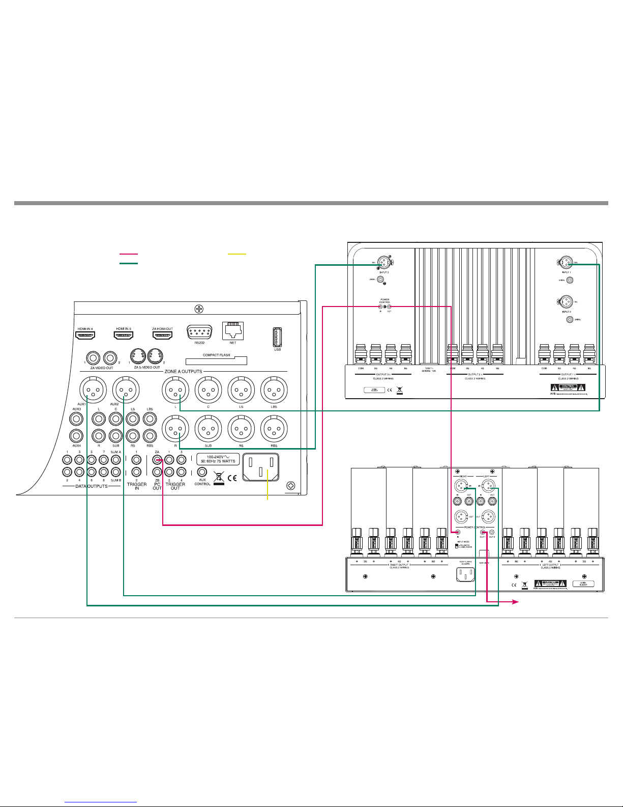
In order to use the AUXiliary Audio Output in the
MX150, for either additional Subwoofer Outputs or
the Electronic Crossover Circuitry, the settings in the
“Installer Speaker Configuration Menu” need to be
changed from their default setting.
The following steps are based on having operated
the MX150 A/V Control Center, including the Setup
Mode. Refer to the MX150 Owner’s Manual - pages 17
thru 45 and the MX150 Installer and User Menu sepa-
rate fold out sheets (supplied in the MX150 Owner’s
Manual Package) for additional information.
In the following example, the Crossover Setting
will be set up for a Bi-Amplified System using McIn-
tosh Loudspeakers with an internal 250Hz crossover
point between the Low Frequency Section and the
Midrange/High Frequency Section. If your Loud-
speakers are not McIntosh, contact your Dealer for
assistance. The MX150 Electronic Crossover Circuitry
will be activated with a crossover setting of 250Hz us-
ing the LinkwitzRiley 4th order filter.
Notes: 1. It is advisable to employ a Real Time Spectrum
Analyzer, with at least one third octave resolu-
tion, to verify correct levels and overall perfor-
mance. RoomPerfectTM Circuitry in the MX150
is designed to correct for Room Acoustics
and Room/Loudspeaker interactions. It is not
intended to correct for Power Amplifiers with
different amplifying gains or Loudspeakers
with inherent irregular frequency responses.
2. When using the MX150 AUX Outputs to drive
multiple Subwoofers instead of using the
MX150 Electronic Crossover Feature for Bi-
Amplifing a Full Range Loudspeaker, select
one of the “Sub _ _ _” crossover point setting”
instead of the “Custom” setting” for “AUX
perform”. Refer to step 6.
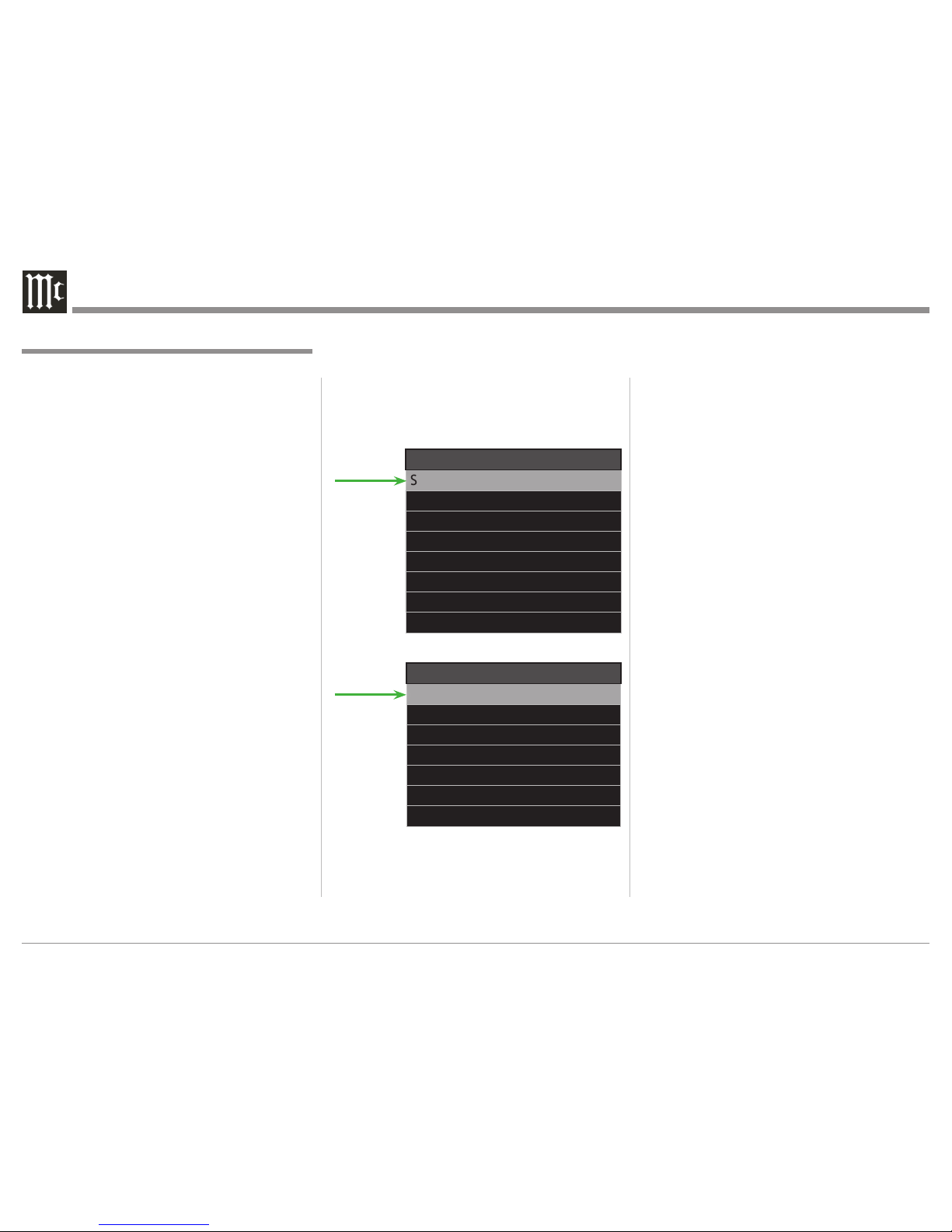
Installer Menu
Speaker and Room Setup
Source Setup
Audio Processing Setup
Zone B Setup
System Setup
Device Management
Exit
Figure 1
Speaker and Room Setup
Speaker Conguration
RoomPerfect
Level Offsets
Distance Settings
Back
Figure 2
1. Switch power On to the MX150 and TV/Monitor.
2. Press the SETUP Push-Button.
3. Select the “Speaker and Room Setup” from the In-
staller Menu. Then select “Speaker Configuration”
from the Speaker and Room Setup Menu. Refer to
figures 1 and 2.
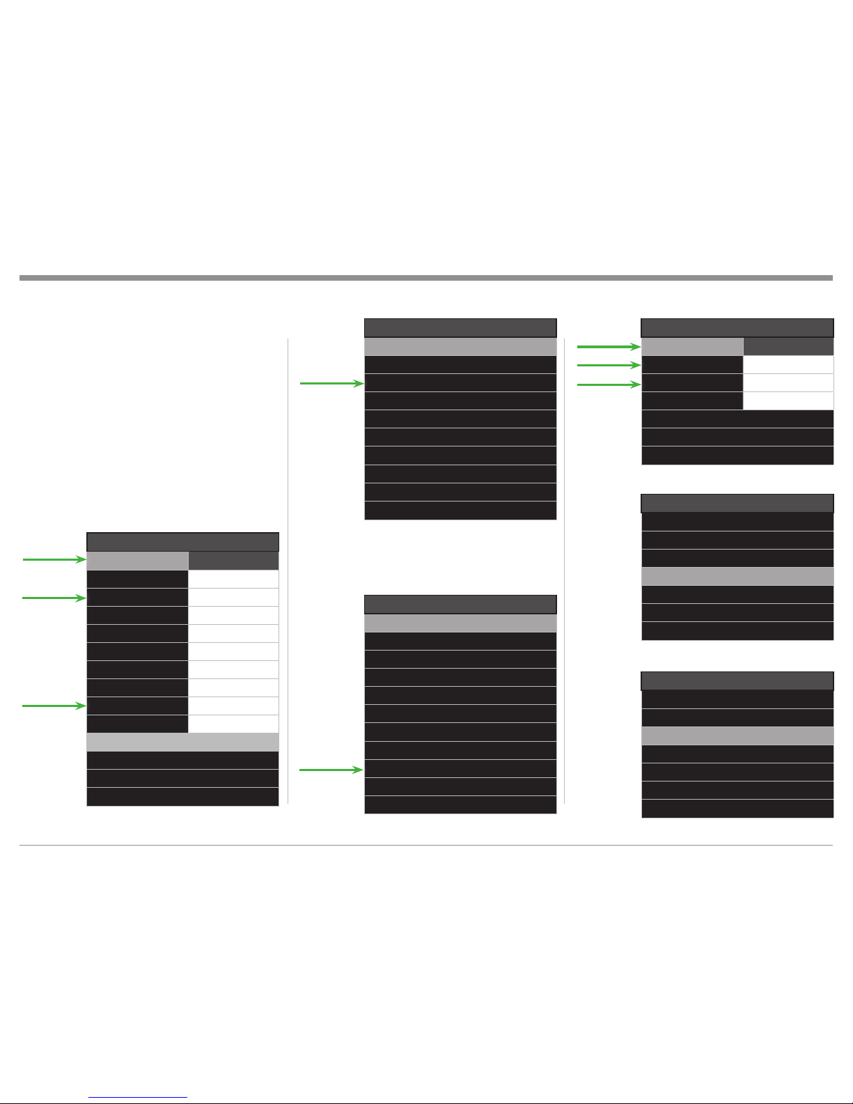
4. To makes changes use the (up) or (down)
Push-buttons to highlight the “EDIT/SELECT”
menu item, then press the SELECT Push-button.
5. Change the “Speaker Configuration” Front Left
and Right settings to either “XL” or XXL” if that
is not the current setting. Refer to figures 3 and
4. Also refer to page 22 of the MX150 Owner’s
Manual for additional information on the “XL”
and XXL” settings.
6. Refering to figures 3, 5 and 6, select “AUX1/2
(L/R)” listed in the Speaker Configuration menu
and change the settings as follows:
AUX perform - Custom
AUX cutoff - 250Hz
AUX order - 4th LiRi
Note: The “Gain Offset” Adjustments for the LEFT
and RIGHT Front Loudspeakers and AUX
Outputs may be used to compensate for the
differences in Power Amplifier gains.
7. Select “Save Change”, followed by Confirm Selec-
tion by selecting “Yes”. Refer to MX150 separate
sheet “Setup 2”
8. Then select “Verify Current Setup” and step thru
all the settings using the SELECT Push-button.
Refer to figures 7 and 8.
Using the previously mentioned acoustic analyzing
equipment, measure and adjust if necessary the gains
of the two Power Amplifiers (unless they have the
same amplification gain) for the same relative levels
across the broad range of frequencies in the Low and
High Pass regions. Then perform RoomPerfect Room
Correction procedures starting on page 24 of the
MX150 Owner’s Manual.
Notes: 1. The analyzing circuitry in the MX150 is
designed to prevent voids in the frequency
response curve. This could occur if the Low
Frequency Output AUX1/2 (L/R) had a cutoff
setting of 125Hz and the the High Frequency
Output (Front L/R) had a cutoff setting of

5
Advanced Setup and Operation Guide
Verify Conguration
Output : L
Volume : -44.0dB
High-pass 80Hz
Continue
Abort
Figure 7
Figure 8
Verify Conguration
Successfully veried
Speaker Conguration
Ok
Speaker Conguration
L XL
CM
RXL
RS M
RBS M
LBS M
LS M
SUB Sub 80
AUX1/2 (L/R) Custom
AUX3/4 (L/R) -
Edit/Select
Verify Current Setup
Back
Figure 3
AUX1/AUX2 (L/R)
AUX perform Custom
AUX cutoff 250Hz
AUX order 4th LiRi
Gain offset 0.0dB
Back
Figure 6
Select Perf.
-
XXL
XL
L
M
S
XS
Custom
Back
Figure 4
Select Perf.
-
Sub 80
Sub 100
Sub 125
Sub 160
Sub 200
Sub 400
Sub 800
Custom
Back
Figure 5
500Hz. In such a case the MX150 would set
the crossover point for both the Low and High
Frequency Outputs to 125Hz.
2. When using both AUX1/2 (Balanced Outputs)
and AUX3/4 (Unbalanced Outputs) at the
same time, it is important to make sure the
settings (AUX perform, AUX cutoff and AUX
order) are set the same. This assures match-
ing of the crossover curves Low Pass and
High Pass, as there is only one set of Front
Left and Front Right Channel Outputs. Refer
to figure 6.
3. When the Electronic Crossover or Multiple
Sub-woofer Mode of operation is active, the
signal normally present at the Subwoofer Out-
put is now available at the AUX Outputs only.

The continuous improvement of its products is the
policy of McIntosh Laboratory Incorporated who
reserve the right to improve design without notice.
Printed in the U.S.A.
McIntosh Laboratory, Inc.
2 Chambers Street
Binghamton, NY 13903
www.mcintoshlabs.com
McIntosh Part No. 04130700
Other manuals for MX150
3
Table of contents
Other McIntosh Music Equipment manuals