www.SteamPoweredRadio.Com
TABLE
OF
CONTENTS
UNPACK
ING
. . . . . • . . . . . . • . . . . . • 1
WARRA.NT'l
.••
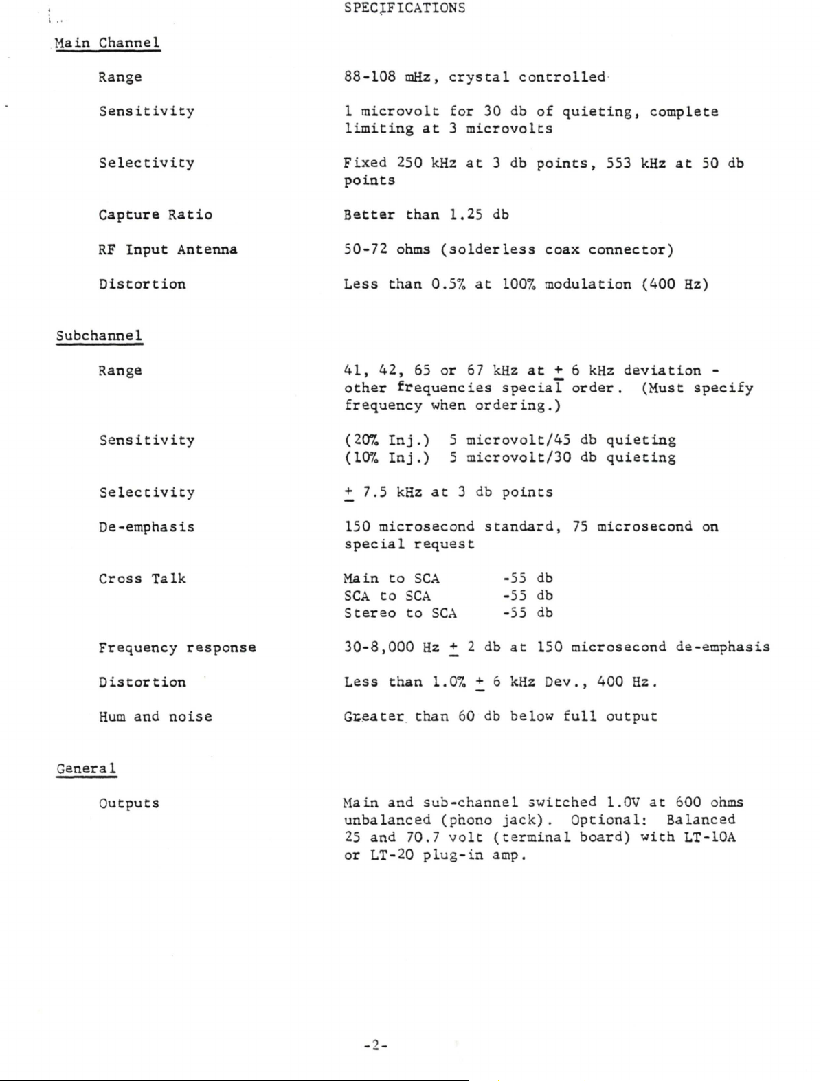
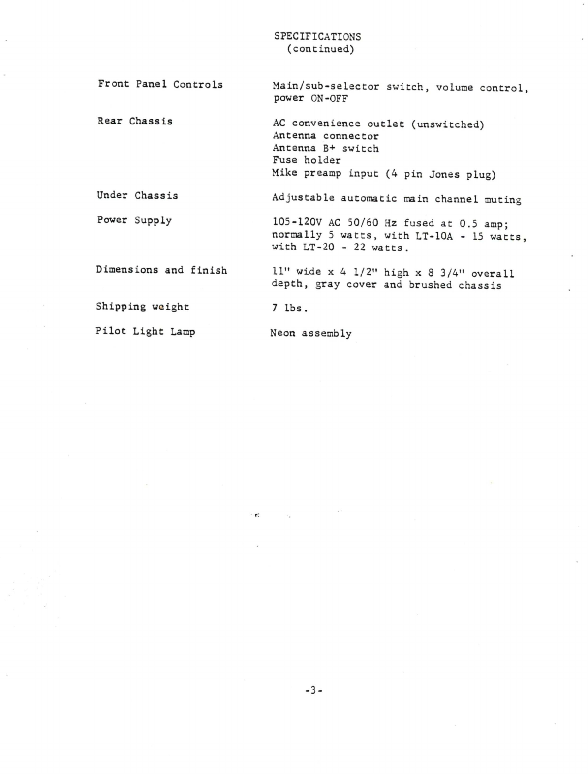
SPECIFICATIONS
•
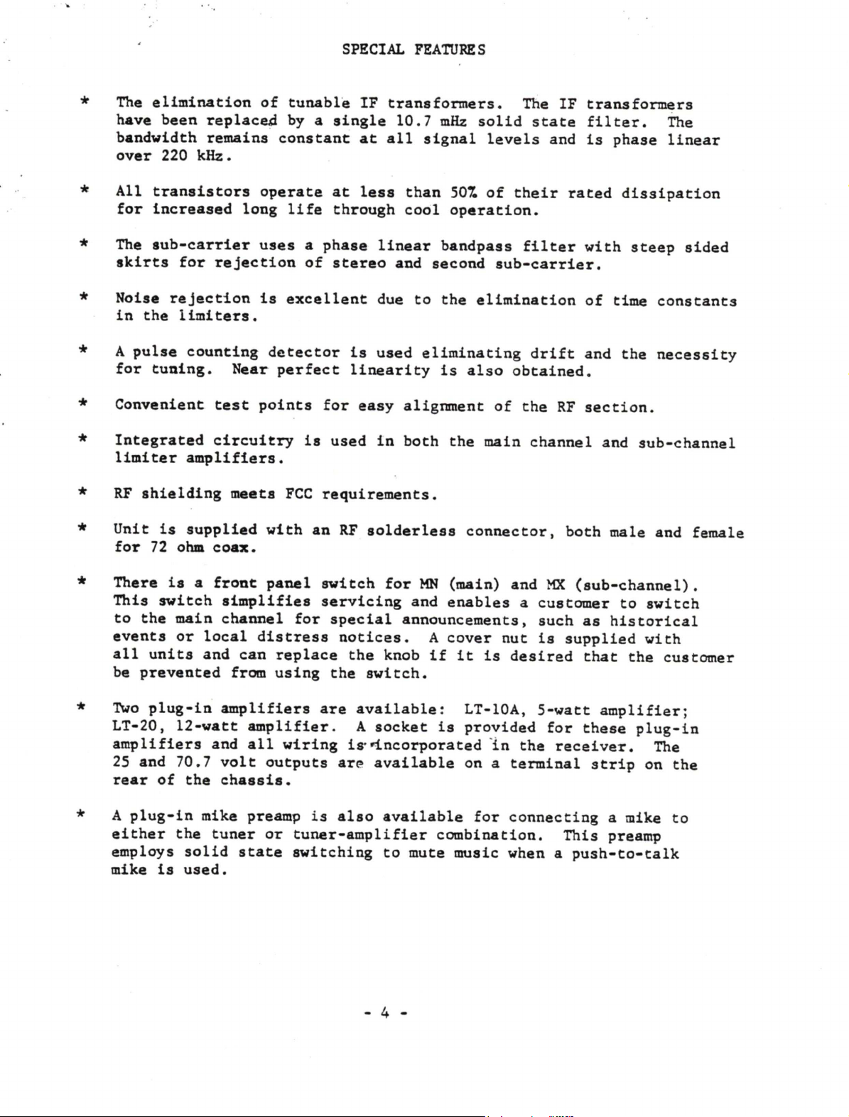
SPECIAL
FEATURES
.
. . .
..
1
• • • 2
• • 4
GENERAL
DESCRIPTION
...•.........•
S
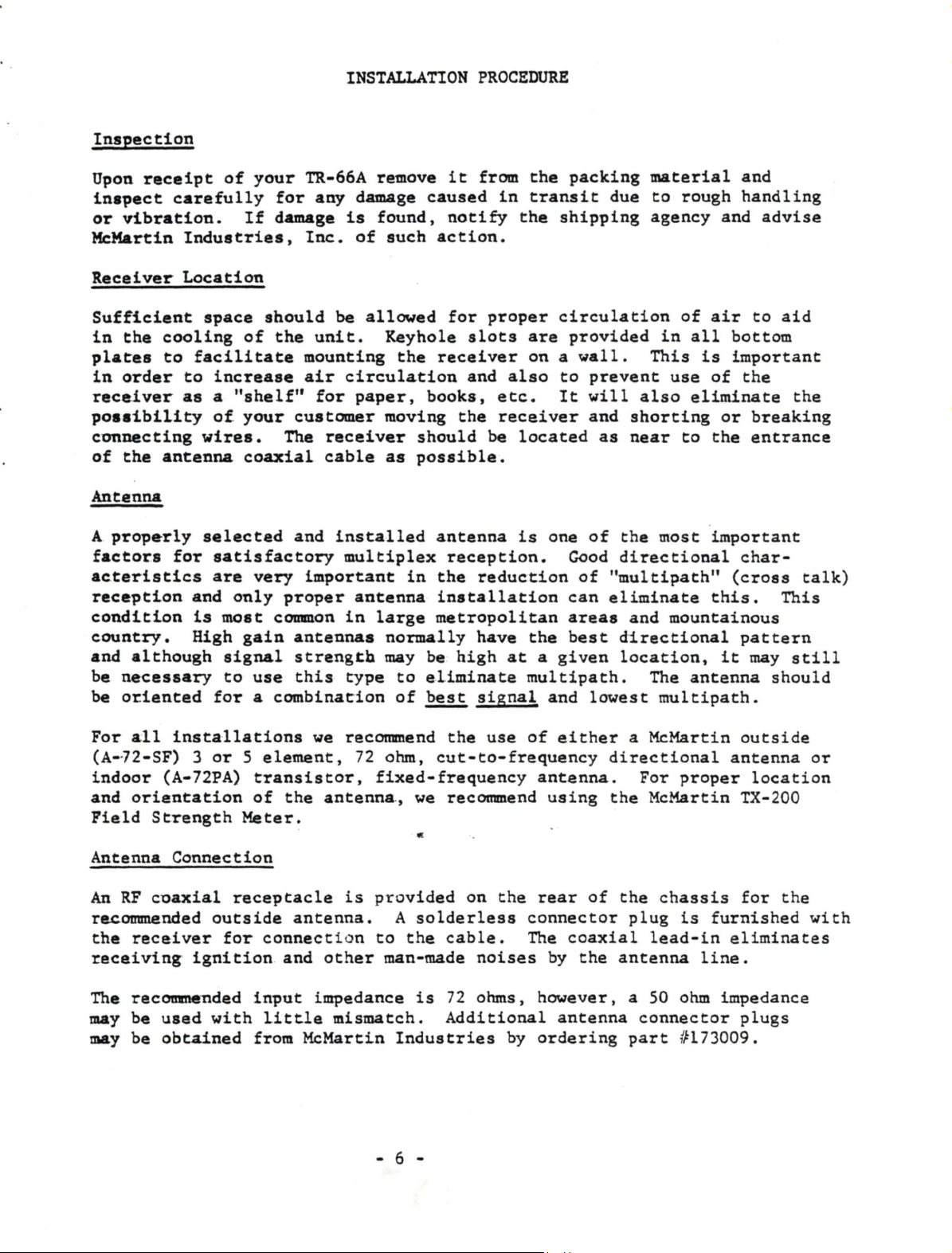
INSTALLATION
PROCEDURE
.......•..•.•
6
FIELD
ADJUSTMENTS
TROUBLESHOOTING
..
• • • 7
TRANSISTOR
AND
DIODE
COMPLEMENT.
SCHEMATICS
• 11
. .12
il
!C
E:
~n
~
EIEI•
CJ
x,uu
il'llk
PIH;
1$
OJ f
l~
~.
=~~
=~
:..:.:
Ul
=U="=
~U~LA_ll-:-u
t.
_S
-===
McMcinin
i~1U<Fid,
inc.
omaha.. ncnrusku