manuals.online logo
Brands
  1. Home
  2. •
  3. Brands
  4. •
  5. McQuay
  6. •
  7. Chiller
  8. •
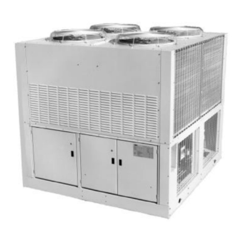
  9. McQuay ACZC SE-ST User manual

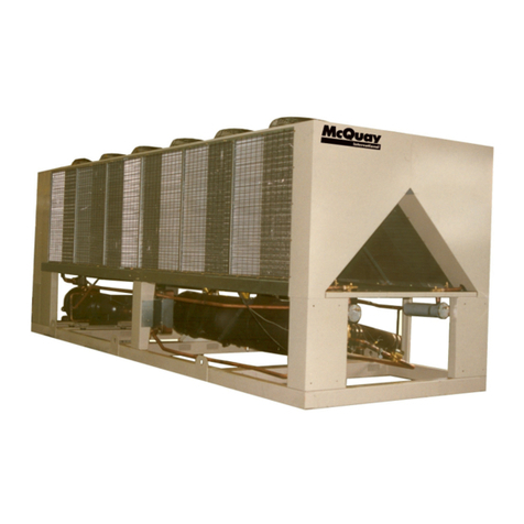
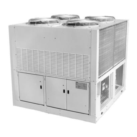
McQuay ACZC SE-ST User manual

EIMAC00806-12EU - 1/212
Installation, Operation and Maintenance Manual
EIMAC00806-12EU
English language: Original Instructions
Date:
June 2012
All other language: Translation of the Original Instructions
Supersedes:
/
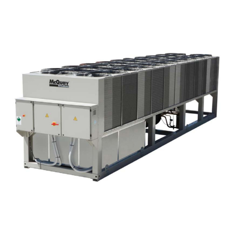
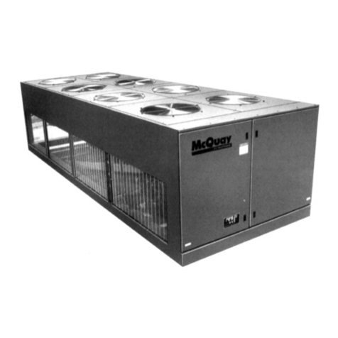
Air cooled scroll chiller
ACZC
6(676WDQGDUG(IILFLHQF\6WDQGDUG1RLVH
6(/16WDQGDUG(IILFLHQF\/RZ1RLVH
6(;16WDQGDUG(IILFLHQF\([WUD/RZ1RLVH
;(67+LJK(IILFLHQF\6WDQGDUG1RLVH
;(/1+LJK(IILFLHQF\/RZ1RLVH
;(;1+LJK(IILFLHQF\([WUD/RZ1RLVH 
Cooling capacity from 171 to 675 kW
Refrigerant: R410A
English.............. 9
Deutsch............ 19
Français ........... 29
Nederlands....... 39
Español............ 49
Italiano ............ 59
ǼȜȜȘȞȚțȐ ......... 69
Português ........ 79
Ɋɭɫɫɤɢɣ .......... 89
Svenska .......... 99
Norsk .............109
Finnish (Suomi) 119
Polski ..............129
ýech ..............139
Hrvat ..............149
Magyar ...........159
Română.........169
Slovensky........179
Ȼɴɥɝɚɪɫɤɢ ......189
Slovenšþina.....199
EIMAC00806-12EU - 2/212
A– Typical refrigerant circuit – The number of compressors and water inlet and outlet are indicative. Please refer to the machine dimensional diagrams for exact water
connections.
A– Typischer Kältemittelkreislaufs – Die Anzahl der Verdampfer und Wasserzu- und ablauf haben Beispielcharakter. Für die genauen Wasseranschlüsse bitte in den Zeichnungen
zur Maschinebemessung nachsehen.
A– Circuit du réfrigérant typique – Le numéro des compresseurs et des entrées et sorties de l'eau est indicatif. Consulter les schémas de dimensions de la machine pour avoir des
indications plus précises sur les connexions de l'eau.
A– Typisch koelcircuit - Het aantal compressors en waterin- en uitlaten is indicatief. Raadpleeg de schema's van de machine voor de exacte wateraansluitingen.
A– Circuito de refrigeración típico – El número de los compresores y de las entradas y salidas de agua es indicativo. Por favor, consulte los diagramas de la máquina para
conocer las conexiones hidráulica exactas.
A– Circuito del refrigerante tipico – Il numero dei compressori e degli ingressi e uscite dell'acqua è indicativo. Consultare i disegni dimensionali della macchina per indicazioni più
precise sulle connessioni dell'acqua.
A– ȉȣʌȚțȩ ȥȣțIJȚțȩ țȪțȜȦȝ – ȅ ȡȚșȝȩȢ IJȦȞ ıȣȝʌȚİıIJȫȞ ț Ț IJȠ Ȟİȡȩ İȚıȩįȠȣ ț Ț İȟȩįȠȣ İȓȞ Ț İȞįİȚțIJȚțȐ. Ȇ ȡ ț Ȝȫ Ȟ IJȡȑȟIJİ ıIJ įȚ ȖȡȐȝȝ IJ įȚ ıIJȐıİȦȞ IJȠȣ ȝȘȤ ȞȒȝ IJȠȢ
ȖȚ IJȚȢ țȡȚȕİȓȢ ıȣȞįȑıİȚȢ ȞİȡȠȪ.
A– Circuito do refrigerante típico – O número de compressores e de ingressos e saídas da água é indicativo. Consultar os desenhos dimensionais da máquina para obter
indicações mais exatas sobre as conexões da água.
A– Ɉɛɵɱɧɵɣ ɤɨɧɬɭɪ ɯɥɚɞɚɝɟɧɬɚ - Ʉɨɥɢɱɟɫɬɜɨ ɤɨɦɩɪɟɫɫɨɪɨɜ, ɜɯɨɞɨɜ ɢ ɜɵɯɨɞɨɜ ɜɨɞɵ - ɨɪɢɟɧɬɢɪɨɜɨɱɧɨɟ. Ȼɨɥɟɟ ɩɨɞɪɨɛɧɵɟ ɭɤɚɡɚɧɢɹ ɩɨ ɩɨɞɤɥɸɱɟɧɢɸ ɜɨɞɵ ɧɚɣɞɺɬɟ ɜ
ɱɟɪɬɟɠɚɯ, ɫɨɞɟɪɠɚɳɢɯ ɪɚɡɦɟɪɵ ɦɚɲɢɧɵ.
A– Typisk köldmediekretsen - Antalet kompressorer och vatten inlopp och utlopp är vägledande. Se maskinens dimensionsritningarna för exakta vattenanslutning.
A– Typisk kjølekrets – Antall kompressorer, vanninnløp og vannutløp er veiledende. Vennligst referer til maskinens måldiagrammer for nøyaktige vannkoblinger.
A– Tyypillinen jäähdytysjärjestelmä – Kompressorien ja veden tulojen ja poistojen lukumäärä on osoittava. Viittaa koneen mitoituspiirroksiin vesiliitäntöihin liittyvää
yksityiskohtaisempaa tietoa varten.
A– Typowy obwód chłodzenia – Liczba sprĊĪarek oraz wlotu i wylotu wody sąwskazujące. Co do dokładnych połączeĔwody prosimy odnieĞü siĊdo schematów wymiarowych
urządzenia.
A– Typický chladící okruh - Poþet kompresorĤa vodních vstupĤa výstupĤje orientaþní. Konzultujte rozmČrové výkresy stroje pro pĜesnČjší informace o vodovodních pĜípojkách.
A– Tipiþan rashladni krug – Broj kompresora i ulaza i izlaza za vodu su samo indikativni. Molimo vas pogledajte dijagrame o dimenzijama stroja radi što toþnijeg položaja
prikljuþaka za vodu.
A– Tipikus hĦtĘkör – A kompresszorok és a víz bemeneti és kimeneti csatlakozási pontjainak száma meghatározó. A pontos vízcsatlakozási jellemzĘkért kérjük, tekintse meg a
gép jellemzĘit tartalmazó diagramokat.
A– Circuit de răcire caracteristic – Numărul compresoarelor úi al punctelor de intrare úi ieúire a apei sunt indicative. Vărugăm consultaĠi diagramele dimensionale ale maúinii
pentru determinarea conexiunilor exacte pentru apă.
A– Typický chladiaci okruh – Poþet kompresorov a vodných vstupov a výstupov je orientaþný. Konzultujte rozmerové výkresy stroja pre presnejšie informácie o vodných
prípojkách.
A– Ɍɢɩɢɱɧɚ ɫɯɟɦɚ ɡɚ ɨɯɥɚɠɞɚɧɟ – Ȼɪɨɹɬ ɧɚ ɤɨɦɩɪɟɫɨɪɢɬɟ ɢ ɜɨɞɧɢɬɟ ɜɯɨɞɨɜɟ ɢ ɢɡɯɨɞɢ ɫɚ ɩɪɢɦɟɪɧɢ. Ɇɨɥɹ ɧɚɩɪɚɜɟɬɟ ɫɩɪɚɜɤɚ, ɫ ɞɢɚɝɪɚɦɚɬɚ ɫ ɪɚɡɦɟɪɢɬɟ ɧɚ ɦɚɲɢɧɚɬɚ,
ɡɚ ɬɨɱɧɢɹ ɛɪɨɣ ɧɚ ɜɨɞɧɢɬɟ ɜɪɴɡɤɢ.
A– Znaþilni krogotok hladilnega sredstva. Število kompresorjev in dovodov ter odvodov za vodo je okvirno. Prikljuþki za vodo so natanþneje prikazani na merskih risbah naprave.
EIMAC00806-12EU - 3/212
A
EIMAC00806-12EU - 4/212
B – Typical refrigerant circuit with heat recovery – The number of compressors and water inlet and outlet are indicative. Please refer to the machine dimensional diagrams for exact
water connections.
B– Typischer Kältemittelkreislaufs Wärmerückgewinnung – Die Anzahl der Verdampfer und Wasserzu- und ablauf haben Beispielcharakter. Für die genauen Wasseranschlüsse
bitte in den Zeichnungen zur Maschinebemessung nachsehen.
B– Circuit du réfrigérant typique avec dispositif de récupération de la chaleur – Le numéro des compresseurs et des entrées et sorties de l'eau est indicatif. Consulter les schémas
de dimensions de la machine pour avoir des indications plus précises sur les connexions de l'eau.
B – Typisch koelcircuit met warmteterugwinning - Het aantal compressors en waterin- en uitlaten is indicatief. Raadpleeg de schema's van de machine voor de exacte
wateraansluitingen.
B– Circuito de refrigeración típico con recuperación de calor – El número de los compresores y de las entradas y salidas de agua es indicativo. Por favor, consulte los diagramas
de la máquina para conocer las conexiones hidráulica exactas.
B– Circuito del refrigerante tipico con dispositivo di recupero del calore – Il numero dei compressori e degli ingressi e uscite dell'acqua è indicativo. Consultare i disegni
dimensionali della macchina per indicazioni più precise sulle connessioni dell'acqua.
Ǻ– ȉȣʌȚțȩ ȥȣțIJȚțȩ țȪțȜȦȝ ȝİ ȞȐțIJȘıȘ șİȡȝȩIJȘIJ Ȣ – ȅ ȡȚșȝȩȢ IJȦȞ ıȣȝʌȚİıIJȫȞ ț Ț IJȠ Ȟİȡȩ İȚıȩįȠȣ ț Ț İȟȩįȠȣ İȓȞ Ț İȞįİȚțIJȚțȐ. Ȇ ȡ ț Ȝȫ Ȟ IJȡȑȟIJİ ıIJ įȚ ȖȡȐȝȝ IJ
įȚ ıIJȐıİȦȞ IJȠȣ ȝȘȤ ȞȒȝ IJȠȢ ȖȚ IJȚȢ țȡȚȕİȓȢ ıȣȞįȑıİȚȢ ȞİȡȠȪ.
B– Circuito do refrigerante típico com dispositivo de recuperação do calor - O número dos compressores e dos ingressos e saídas da água é indicativo. Consultar os desenhos
dimensionais da máquina para indicações mais exatas sobre as conexões da água.
B– Ɉɛɵɱɧɵɣ ɤɨɧɬɭɪ ɯɥɚɞɚɝɟɧɬɚ ɫ ɭɫɬɪɨɣɫɬɜɨɦ ɞɥɹ ɭɬɢɥɢɡɚɰɢɢ ɬɟɩɥɨɬɵ - Ʉɨɥɢɱɟɫɬɜɨ ɤɨɦɩɪɟɫɫɨɪɨɜ, ɜɯɨɞɨɜ ɢ ɜɵɯɨɞɨɜ ɜɨɞɵ - ɨɪɢɟɧɬɢɪɨɜɨɱɧɨɟ. Ȼɨɥɟɟ ɩɨɞɪɨɛɧɵɟ
ɭɤɚɡɚɧɢɹ ɩɨ ɩɨɞɤɥɸɱɟɧɢɸ ɜɨɞɵ ɧɚɣɞɺɬɟ ɜ ɱɟɪɬɟɠɚɯ, ɫɨɞɟɪɠɚɳɢɯ ɪɚɡɦɟɪɵ ɦɚɲɢɧɵ.
B – Typisk köldmediekretsen med värmeåtervinning - Antalet kompressorer och vatten inlopp och utlopp är vägledande. Se maskinens dimensionella diagram för exakta
vattenanslutningar.
B– Typisk kjølekrets med varmegjenvinning – Antall kompressorer, vanninnløp og vannutløp er veiledende. Vennligst referer til maskinens måldiagrammer for nøyaktige
vannkoblinger.
B– Tyypillinen jäähdytysjärjestelmä lämmön talteenotolla – Kompressorien ja veden tulojen ja poistojen lukumäärä on osoittava. Viittaa koneen mitoituspiirroksiin vesiliitäntöihin
liittyvää yksityiskohtaisempaa tietoa varten.
B – Typowy obwód chłodzenia z odzyskiwaniem ciepła – Liczba sprĊĪarek oraz wlotu i wylotu wody sąwskazujące. Co do dokładnych połączeĔwody prosimy odnieĞü siĊdo
schematów wymiarowych urządzenia.
B – Typický chladící okruhse zaĜízením na rekuperaci tepla - Poþet kompresorĤa vodních vstupĤa výstupĤje orientaþní. Konzultujte rozmČrové výkresy stroje pro pĜesnČjší
informace o vodovodních pĜípojkách.
B– Tipiþan rashladni krug s povratom topline – Broj kompresora i ulaza i izlaza za vodu su samo indikativni. Molimo vas pogledajte dijagrame o dimenzijama stroja radi što
toþnijeg položaja prikljuþaka za vodu.
B – Tipikus hĦtĘkör hĘvisszanyerĘvel– A kompresszorok és a víz bemeneti és kimeneti csatlakozási pontjainak száma meghatározó. A pontos vízcsatlakozási jellemzĘkért kérjük,
tekintse meg a gép jellemzĘit tartalmazó diagramokat.
B – Circuit de răcire cu recuperare de căldurăcaracteristic – Numărul compresoarelor úi al punctelor de intrare úi ieúire a apei sunt indicative. ConsultaĠi diagramele dimensionale
ale maúinii pentru identificarea exactăa conexiunilor de apă.
B– Typický chladiaci okruh so zariadením na rekuperáciu tepla – Poþet kompresorov a vodných vstupov a výstupov je orientaþný. Konzultujte rozmerové výkresy stroja pre
presnejšie informácie o vodných prípojkách.
B – Ɍɢɩɢɱɧɚ ɫɯɟɦɚ ɡɚ ɨɯɥɚɠɞɚɧɟ ɫ ɢɡɩɨɥɡɜɚɧɟ ɧɚ ɬɨɩɥɢɧɚ – Ȼɪɨɹɬ ɧɚ ɤɨɦɩɪɟɫɨɪɢɬɟ ɢ ɜɨɞɧɢɬɟ ɜɯɨɞɨɜɟ ɢ ɢɡɯɨɞɢ ɫɚ ɩɪɢɦɟɪɧɢ. Ɇɨɥɹ ɧɚɩɪɚɜɟɬɟ ɫɩɪɚɜɤɚ, ɫ ɞɢɚɝɪɚɦɚɬɚ ɫ
ɪɚɡɦɟɪɢɬɟ ɧɚ ɦɚɲɢɧɚɬɚ, ɡɚ ɬɨɱɧɢɹ ɛɪɨɣ ɧɚ ɜɨɞɧɢɬɟ ɜɪɴɡɤɢ.
B – Znaþilni krogotok hladilnega sredstva z rekuperacijo toplote. Število kompresorjev in dovodov ter odvodov za vodo je okvirno. Prikljuþki za vodo so natanþneje prikazani na
merskih risbah naprave.
EIMAC00806-12EU - 5/212
B
EIMAC00806-12EU - 6/212
ENGLISH DEUTSCH FRANÇAIS NEDERLANDS ESPAÑOL ITALIANO ǼȁȁǾȃǿȀǹ
1
Compressor Verdichter Compresseur Compressor Compresor Compressore ȈȣȝʌȚİıIJȒȢ
2
Discharge shut off valve Absperrventil Druckleitung Robinet d'évacuation Afvoerklep Válvula de cierre de descarga Rubinetto di scarico ǼțijȩȡIJȦıȘ ȕ Ȝȕȓį Ȣ țȜİȚıȓȝ IJȠȢ
3
¼ SAE Flare Valve ¼ SAE Flare Ventil Vanne ¼ SAE Flare ¼ SAE Opruimklep Válvula ¼ SAE Flare Valvola ¼ SAE Flare ¼ SAE ĭȦIJȠȕȠȜȓį ȕ Ȝȕȓį Ȣ
4 Condenser coil and Axial
ventilator
Verflüssigerregister und
Axialventilator
Batterie à condensation et
ventilateur axial
Condensatorwikkeling en Axiale
ventilator
Serpentín del condensador y
Ventilador axial
Batteria condensante e
ventilatore assiale ȆȘȞȓȠ ıȣȝʌȣțȞȦIJȒ ț Ț ǹȟȠȞȚțȩȢ
ȞİȝȚıIJȒȡ Ȣ
5
Service port Betriebsanschluss Port de maintenance Dienstpoort Abertura de servicio Portello per assistenza ȊʌȘȡİıȓ șȪȡ Ȣ
6 Liquid line isolating valve Selbstschlussventil
Flüssigkeitsleitung
Vanne d'isolement de la ligne du
liquide Afsluitklep vloeistoflijn Válvula de aislamiento de la línea
del líquido Valvola isolante linea del liquido īȡ ȝȝȒ ȣȖȡȠȪ ȕ Ȝȕȓį Ȣ
ʌȠȝȩȞȦıȘȢ
7
Dehydration filter Entwässerungsfilter Filtre déshydrateur Dehydratatiefilter Filtro deshidratador Filtro deidratatore ĭȓȜIJȡȠ ijȣįȐIJȦıȘȢ
8 Liquid and humidity indicator Flüssigkeits- und
Feuchtigkeitsanzeiger Indicateur de liquide et humidité Indictaor vloeistof en vochtigheid Indicador de líquido y humedad Indicatore di liquido e umidità ȊȖȡȩ ț Ț įİȓțIJȘȢ ȣȖȡ ıȓ Ȣ
9
Solenoid valve Solenoidventil Vanne solénoïde Elektromagnetische klep Válvula solenoide Valvola solenoide ǾȜİțIJȡȠȝ ȖȞȘIJȚțȒ ȕ Ȝȕȓį
10
Electronic expansion valve Elektronisches Expansionsventil Détendeur électronique Elektronische expansieklep Válvula de expansión electrónica Valvola di espansione elettronica ǾȜİțIJȡȠȞȚțȒ ȕ Ȝȕȓį İțIJȩȞȦıȘȢ
11
Evaporator Verdampfer Evaporateur Verdamper Evaporador Evaporatore Ǽȟ IJȝȚıIJȒȢ
12
Suction shut off valve Absperrventil Ansaugleitung Robinet d'aspiration Afsluitklep aanzuiging Válvula de cierre aspiración Rubinetto di aspirazione ǹȞ ȡȡȩijȘıȘ ȕ Ȝȕȓį Ȣ țȜİȚıȓȝ IJȠȢ
13 Low-pressure safety valve Niederdruck-Sicherheitsventil Soupape de sécurité à basse
pression Veiligheidsklep lage druk Válvula de seguridad de baja
presión
Valvola di sicurezza a bassa
pressione ȋ ȝȘȜȒ-ʌȓİıȘ ȕ Ȝȕȓį Ȣ ıij Ȝİȓ Ȣ
14 High-pressure safety valve Hochdruck-Sicherheitsventil Soupape de sécurité haute
pression Veiligheidsklep hoge druk Válvula de seguridad de alta
presión
Valvola di sicurezza alta
pressione ȊȥȘȜȒ-ʌȓİıȘ ȕ Ȝȕȓį Ȣ ıij Ȝİȓ Ȣ
15 Heat recovery (optional) Wärmerückgewinnung (optional) Dispositif de récupération de la
chaleur (en option)
Inrichting voor warmteterugwinning
(optie) Recuperador de calor (opcional) Dispositivo di recupero del
calore (opzionale) ǹȞȐțIJȘıȘ șİȡȝȩIJȘIJ Ȣ (ʌȡȠ ȚȡİIJȚțȩ)
16 (YR)
Heat recovery solenoid valve
(only for total heat recovery
version)
Solenoidventil
Wärmerückgewinnung (nur für
Version mit totaler
Wärmerückgewinnung)
Vanne solénoïde de récupération
de la chaleur (seulement dans la
version à récupération totale de la
chaleur)
Elektomagnetische klep
warmteterugwinning
(alleen voor versie met totale
warmteterugwinning)
Válvula solenoide del recuperador
de calor (sólo para versión con
recuperador de calor total)
Valvola solenoide recupero del
calore (solo nella versione a
recupero totale del calore)
ǹȞȐțIJȘıȘ șİȡȝȩIJȘIJ Ȣ
ȘȜİțIJȡȠȝ ȖȞȘIJȚțȒȢ ȕ Ȝȕȓį Ȣ (ȝȩȞȠ
ȖȚ IJȘȞ ȑțįȠıȘ ıȣȞȠȜȚțȒȢ
ȞȐțIJȘıȘȢ șİȡȝȩIJȘIJ Ȣ)
17
Heat recovery thermostatic
expansion valve
(only for total heat recovery
version)
Wärmerückgewinnung
thermostatische Expansionsventil
(nur für Version mit totaler
Wärmerückgewinnung)
Détendeur thermostatique du
dispositif de récupération de la
chaleur (seulement dans la version
à récupération totale de la chaleur)
Thermostatische expansieklep
warmteterugwinning
(alleen voor versie met totale
warmteterugwinning)
Válvula de expansión termostática
del recuperador de calor (sólo para
versión con recuperador de calor
total)
Valvola di espansione
termostatica dispositivo di
recupero del calore (solo nella
versione a recupero totale del
calore)
ĬİȡȝȠıIJ IJȚțȒ ȞȐțIJȘıȘ șİȡȝȩIJȘIJ Ȣ
ȕ Ȝȕȓį Ȣ İțIJȩȞȦıȘȢ (ȝȩȞȠ ȖȚ IJȘȞ
ȑțįȠıȘ ıȣȞȠȜȚțȒȢ ȞȐțIJȘıȘȢ
șİȡȝȩIJȘIJ Ȣ)
18 Subcooler (only for total heat
recovery version)
Unterkühler (nur für Version mit
totaler Wärmerückgewinnung)
Sous-refroidisseur seulement dans
la version à récupération totale de
la chaleur)
Nakoeler (alleen voor versie met
totale warmteterugwinning)
Subenfriador (sólo para versión
con recuperador de calor total)
Sottoraffreddatore (solo nella
versione a recupero totale del
calore)
ȊʌȠȥȪțIJȘȢ (ȝȩȞȠ ȖȚ IJȘȞ ȑțįȠıȘ
ıȣȞȠȜȚțȒȢ ȞȐțIJȘıȘȢ șİȡȝȩIJȘIJ Ȣ)
19
Water inlet connection Wasserzulaufanschluss Connexion entrée eau Aansluiting waterinlaat Conexión de entrada de agua Connessione ingresso acqua ȈȪȞįİıȘ ȞİȡȠȪ İȚıȩįȠȣ
20
Water outlet connection Wasserablaufanschluss Connexion sortie eau Aansluiting wateruitlaat Conexión de salida de agua Connessione uscita acqua ȈȪȞįİıȘ ȞİȡȠȪ İȟȩįȠȣ
EP
Low-pressure transducer Niederdruckwandler Transducteur basse pression Transductor lage druk Transductor de baja presión Trasduttore bassa pressione ȋ ȝȘȜȒȢ-ʌȓİıȘȢ ȝİIJ IJȡȠʌȑ Ȣ
CP
High-pressure transducer Hochdruckwandler Transducteur haute pression Transductor hoge druk Transductor de alta presión Trasduttore alta pressione ȊȥȘȜȒȢ-ʌȓİıȘȢ ȝİIJ IJȡȠʌȑ Ȣ
F13
High-pressure switch Maximum-Druckwächter Pressostat de haute pression Hogedrukschakelaar Interruptor de alta presión Pressostato di alta ǻȚ țȩʌIJȘȢ ȣȥȘȜȒȢ ʌȓİıȘȢ
MP1 Motor thermistor compressor 1 Motorthermistor Verdichter 1 Compresseur thermistance moteur
1 Motor thermistor compressor 1 Termistor del motor del compresor
1
Compressore termistore motore
1 ȀȚȞȘIJȒȡ Ȣ șİȡȝȠıIJȐIJȘ ıȣȝʌȚİıIJȒ 1
MP2 Motor thermistor compressor 2 Motorthermistor Verdichter 2 Compresseur thermistance moteur
2 Motor thermistor compressor 2 Termistor del motor del compresor
2
Compressore termistore motore
2 ȀȚȞȘIJȒȡ Ȣ șİȡȝȠıIJȐIJȘ ıȣȝʌȚİıIJȒ 2
MP3 Motor thermistor compressor 3 Motorthermistor Verdichter 3 Compresseur thermistance moteur
3 Motor thermistor compressor 3 Termistor del motor del compresor
3
Compressore termistore motore
3 ȀȚȞȘIJȒȡ Ȣ șİȡȝȠıIJȐIJȘ ıȣȝʌȚİıIJȒ 3
EEWT Evaporator Entering Water
Temperature probe
Temperaturfühler Wasserzulauf
Verdampfer
Sonde de température de l'eau de
l'évaporateur en entrée
Temperatuursonde
binnenstromend water verdamper
Sonda temperatura del agua en
entrada en el evaporador
Sonda temperatura acqua
evaporatore in ingresso Ǽȟ IJȝȚıIJȒȢ ǼȚıİȡȤȩȝİȞȠȣ ȃİȡȠȪ
ĬİȡȝȠțȡ ıȓ Ȣ ȚıșȘIJȒȡ
ELWT Evaporator Leaving Water
Temperature probe
Temperaturfühler Wasserablauf
Verdampfer
Sonde de température de l'eau de
l'évaporateur en sortie
Temperatuursonde uitstromend
water verdamper
Sonda temperatura del agua en
salida del evaporador
Sonda temperatura acqua
evaporatore in uscita Ǽȟ IJȝȚıIJȒȢ ǼȟİȡȤȩȝİȞȠȣ ȃİȡȠȪ
ĬİȡȝȠțȡ ıȓ Ȣ ȚıșȘIJȒȡ
HREWT
Heat Recovery Entering Water
Temperature probe (only for total
heat recovery version)
Temperaturfühler Wasserzulauf
Wärmerückgewinnung (nur für
Version mit totaler
Wärmerückgewinnung)
Sonde de température de l'entrée
d'eau de récupération de chaleur
(seulement dans la version à
récupération totale de la chaleur)
Temperatuursonde
binnenstromend water
warmteterugwinning
(alleen voor versie met totale
warmteterugwinning)
Sonda temperatura del agua en
entrada en el recuperador de calor
(sólo para versión con recuperador
de calor total)
Sonda temperatura ingresso
acqua recupero di calore (solo
nella versione a recupero totale
del calore)
ǹȞȐțIJȘıȘ ĬİȡȝȩIJȘIJ Ȣ ǼȚıȩįȠȣ
ȃİȡȠȪ șİȡȝȠțȡ ıȓ Ȣ ȚıșȘIJȒȡ
(ȝȩȞȠ ȖȚ IJȘȞ ȑțįȠıȘ ıȣȞȠȜȚțȒȢ
ȞȐțIJȘıȘȢ șİȡȝȩIJȘIJ Ȣ)
HRLWT
Heat Recovery Leaving Water
Temperature probe
(only for total heat recovery
version)
Temperaturfühler Wasserablauf
Wärmerückgewinnung (nur für
Version mit totaler
Wärmerückgewinnung)
Sonde de température de la sortie
d'eau de récupération de chaleur
(seulement dans la version à
récupération totale de la chaleur)
Temperatuursonde uitstromend
water warmteterugwinning
(alleen voor versie met totale
warmteterugwinning)
Sonda temperatura del agua en
salida del recuperador de calor
(sólo para versión con recuperador
de calor total)
Sonda temperatura uscita acqua
recupero di calore (solo nella
versione a recupero totale del
calore)
ǹȞȐțIJȘıȘ ĬİȡȝȩIJȘIJ Ȣ ǼȟİȡȤȩȝİȞȠȣ
ȃİȡȠȪ șİȡȝȠțȡ ıȓ Ȣ ȚıșȘIJȒȡ
(ȝȩȞȠ ȖȚ IJȘȞ ȑțįȠıȘ ıȣȞȠȜȚțȒȢ
ȞȐțIJȘıȘȢ șİȡȝȩIJȘIJ Ȣ)
EIMAC00806-12EU - 9/212
ENGLISH - ORIGINAL INSTRUCTIONS
This manual is an important supporting document for qualified personnel but it is not intended to replace such personnel.
Thank you for purchasing this chiller
READ THIS MANUAL CAREFULLY BEFORE
INSTALLING AND STARTING UP THE UNIT.
IMPROPER INSTALLATION COULD RESULT IN
ELECTRIC SHOCK, SHORT-CIRCUIT, LEAKS, FIRE
OR OTHER DAMAGE TO THE EQUIPMENT OR
INJURE TO PEOPLE.
THE UNIT MUST BE INSTALLED BY A
PROFESSIONAL OPERATOR/TECHNICIAN.
UNIT STARTUP HAS TO BE PERFORMED BY
AUTHORIZED AND TRAINED PROFESSIONAL.
ALL ACTIVITIES HAVE TO BE PERFORMED
ACCORDING TO LOCAL LAWS AND REGULATION.
UNIT INSTALLATION AND START UP IS
ABOSOLUTELY FORBIDDEN IF ALL INSTRUCTION
CONTAINED IN THIS MANUAL ARE NOT CLEAR.
IF CASE OF DOUBT CONTACT THE
MANUFACTURER REPRESENTATIVE FOR ADVICE
AND INFORMATION.
Description
The unit you bought is an “air cooled chiller”, a machine aimed
to cool water (or water-glycol mixture) within the limits
described in the following. The unit operation is based on
vapour compression, condensation and evaporation according
to reverse Carnot cycle.The main components are:
- Scroll compressor to rise the refrigerant vapour pressure
from evaporation pressure to condensation pressure.
- Evaporator, where the low pressure liquid reqrigerant
evaporates so cooling the water.
- Condenser, where high pressure vapour condensate
rejecting heat removed from the chilled water in the
atmosphere thanks to an air cooled heat exchanger.
- Expansion valve allowing to reduced the pressure of
condensed liquid from condensation pressure to
evaporation pressure.
General Information
All units are delivered with wiring diagrams, certified
drawings, nameplate; and DOC (Declaration Of
Conformity); these documents show all technical data
for the unit you have bought and they MUST BE
CONSIDERED ESSENTIAL DOCUMENTS OF THIS
MANUAL
In case of any discrepancy between this manual and the
equipment’s documents please refer to on board documents.
In case of any doubt contact the manufacturer representative.
The purpose of this manual is to allow the installer and the
qualified operator to ensure proper installation, commissioning
and maintenance of the unit, without any risk to people,
animals and/or objects.
Receiving the unit
The unit must be inspected for any possible damage
immediately upon reaching final place of installation. All
components described in the delivery note must be inspected
and checked.
Should the unit be damaged, do not remove the damaged
material and immediately report the damage to the
transportation company and request they inspect the unit.
Immediately report the damage to the manufacturer
representative, a set of photographs are helpful in recognizing
responsibility
Damage must not be repaired before the inspection of the
transportation company representative.
Before installing the unit, check that the model and power
supply voltage shown on the nameplate are correct.
Responsibility for any damage after acceptance of the unit
cannot be attributed to the manufacturer.
Operating limits
Storing
Environmental conditions must be within the following limits:
Minimum ambient temperature : -20°C
Maximum ambient temperature : +42°C
Maximum R.H. : 95% not condensing
Storing below the minimum temperature may cause damage to
components. Storing above the maximum temperature causes
opening of safety valves. Storing in condensing atmosphere
may damage electronic components.
Operation
Operation is allowed within the limits mentioned in Figure 2.
The unit must be operated with an evaporator water flow rate
between 50% and 140% of nominal flow rate (at standard
operating conditions).
Operation out of the mentioned limits may damage the unit.
In case of doubts contact manufacturer representative.
Figure 1 - Description of the labels applied to the electrical panel
Label Identification
1
– Non flammable gas symbol
5
– Cable tightening warning
2
– Gas type
6
– Electrical hazard symbol
3
– Manufacturer’s logo
7
– Lifting instructions
4
– Hazardous Voltage warning
8
– Unit nameplate data
EIMAC00806-12EU - 10/212
Label Identification
Figure 2 - Operating limits
Note
The above graphic represents a guidelines about the operating limits of the range. Please refer to Chiller Selection Software
(CSS) for real operating limits working conditions for each size.
Legend
CIAT = Condenser Inlet Air Temperature (°C)
ELWT = Evaporator Leaving Water Temperature (°C)

A= Operation with Glycol (below 4°C Evap LWT)
B= Fan speed modulation or Speedtroll required (below 10°C Condens. Air Temp.)
C= Fan speed modulation or Speedtroll required (below 10°C and up to -10°C Condens. Air Temp.)*
*Only referred to units with 4-5-6 fans
D= In this area units can work at partial load
E= In this area the unit minimum capacity might be higher than value shown in Technical Specification table
F= Standard Efficiency (standard sound)
G= High Efficiency (standard sound)
1
– Non flammable gas symbol
5
– Cable tightening warning
2
– Gas type
6
– Hazardous Voltage warning
3
– Unit nameplate data
7
– Electrical hazard symbol
4
– Manufacturer’s logo
8
– Lifting instructions
1RWH

D
G
F
E
B
C
A
EIMAC00806-12EU - 11/212
Safety
The unit must be firmly secured to the soil.
It is essential to observe the following instructions:
−The unit can only be lifted using the lifting points marked
in yellow fixed to its base.
−It is forbidden to access the electrical components without
having opened the unit main switch and switched off the
power supply.
−It is forbidden to access the electrical components without
using an insulating platform. Do not access the electrical
components if water and/or moisture are present.
−Sharp edges and the surface of the condenser section
could cause injury. Avoid direct contact and use adeguate
protection device
−Switch off power supply, by opening the main switch,
before servicing the cooling fans and/or compressors.
Failure to observe this rule could result in serious
personal injury.
−Do not introduce solid objects into the water pipes while
the unit is connected to the system.
−A mechanical filter must be installed on the water pipe
connected to the heat exchanger inlet.
−The unit is supplied with safety valves, that are installed
both on the high-pressure and on the low-pressure sides
of the refrigerant circuit.
It is absolutely forbidden to remove all protections of
moving parts.
In case of sudden stop of the unit, follow the instructions on the
Control Panel Operating Manual which is part of the on-
board documentation delivered to the end user.
It is strongly recommended to perform installation and
maintenance with other people. In case of accidental injury or
unease, it is necessary to:
-keep calm
-press the alarm button if present in the installation site
-move the injured person in a warm place far from the unit
and in rest position
-contact immediately emergency rescue personnel of the
building or the Health Emergency Service
-wait without leaving the injured person alone until the
rescue operators come
-give all necessary information to the the rescue operators
Avoid installing the chiller in areas that could be
dangerous during maintenance operations, such as
platforms without parapets or railings or areas not
complying with the clearance requirements around the
chiller.
Noise
The unit is a source of noise mainly due to rotation of
compressors and fans.
The noise level for each model size is listed in sales
documentation.
If the unit is correctly installed, operated and manteined the
noise emission level do not require any special protection
device to operate continuosly close to the unit without any risk.
In case of installation with special noise requirements it could
be necessary to install additional sound attenuation devices.
Moving and lifting
Avoid bumping and/or jolting during loading/unloading unit
from the truck and moving it. Do not push or pull the unit from
any part other than the base frame. Secure the unit inside the
truck to prevent it from moving and causing damages. Do not
allow any part of the unit to fall during transportation or
loading/unloading.
All units are supplied with the lifting points marked in yellow.
Only these points may be used for lifting the unit, as shown in
the following Figure 3.
Both the lifting ropes and the spacing bars must be
strong enough to support the unit safely. Please check
the unit’s weight on the unit nameplate.
The unit must be lifted with the utmost attention and care
following lifting label instructions; lift unit very slowly, keeping it
perfectly level.
Positioning and assembly
All units are designed for installation outdoors, either on
balconies or on the ground, provided that the installation area
is free of obstacles that could reduce air flow to the
condensers coil.
The unit must be installed on a robust and perfectly level
foundation; should the unit be installed on balconies or roofs, it
might be necessary to use weight distribution beams.
EIMAC00806-12EU - 12/212
Figure 3 - Lifting the unit
4 fans version
5 fans version
EIMAC00806-12EU - 13/212
6 fans version
6 fans version
EIMAC00806-12EU - 14/212
10-12 fans version
(The drawing shows only the 8 fans version. For the 10-12 fans version the lifting mode is the same)
For installation on the ground, a strong concrete base, at least
250 mm thickness and wider than the unit must be provided.
This base must be able to support the weight of the unit.
If the unit is installed in places that are easily accessible to
people and animals, it is advisable to install protection grids for
the condenser and compressor sections.
To ensure best performance on the installation site, the
following precautions and instructions must be followed:
−Avoid air flow recirculation.
−Make sure that there are no obstacles to hamper air flow.
−Make sure to provide a strong and solid foundation to
reduce noise and vibrations.
−Avoid installation in particularly dusty environments, in
order to reduce soiling of condensers coils.
−The water in the system must be particularly clean and all
traces of oil and rust must be removed. A mechanical
water filter must be installed on the unit’s inlet piping.
Minimum space requirements
It is fundamental to respect minimum distances on all units in
order to ensure optimum ventilation to the condenser coils.
When deciding where to position the unit and to ensure a
proper air flow, the following factors must be taken into
consideration:
−avoid any warm air recirculation
−avoid insufficient air supply to the air-cooled condenser.
Both these conditions can cause an increase of condensing
pressure, which leads to a reduction in energy efficiency and
refrigerating capacity.
Any side of the unit must be accessible for post-installation
maintenance operations. Figure 4 shows the minimum space
required.
Vertical air discharge must not be obstructed.
If the unit is surrounded by walls or obstacles of the same
height as the unit, this must be installed at a distance no lower
than (see Figure 4C or 4D). If these obstacles are higher, the
unit must be installed at a distance no lower (see Figure 4E or
4F).
Should the unit be installed without observing the
recommended minimum distances from walls and/or vertical
obstacles, there could be a combination of warm air
recirculation and/or insufficient supply to the air-cooled
condenser which could cause a reduction of capacity and
efficiency.
In any case, the microprocessor will allow the unit to adapt
itself to new operating conditions and deliver the maximum
available capacity under any given circumstances, even if the
lateral distance is lower than recommended, unless the
operating conditions should affect personel safety or unit
reliability.
When two or more units are positioned side by side, a distance
of at least (see Figure 4G or 4H) between condenser banks is
recommended.
For further solutions, please consult manufacturer
representative.
Sound protection
When sound levels require special control, great care must be
exercised to isolate the unit from its base by appropriately
applying anti-vibration elements (supplied as an option).
Flexible joints must be installed on the water connections, as
well.
Water piping
Piping must be designed with the lowest number of elbows
and the lowest number of vertical changes of direction. In this
way, installation costs are reduced considerably and system
performance is improved.
The water system must have:
1. Anti-vibration mountings in order to reduce transmission of
vibrations to the structures.
2. Isolating valves to isolate the unit from the water system
during service.
3. Manual or automatic air venting device at the system’s
highest point.; drain device at the system’s lowest point.
4. Neither the evaporator nor the heat recovery device must
be positioned at the system’s highest point.
5. A suitable device that can maintain the water system under
pressure (expansion tank, etc.).
6. Water temperature and pressure indicators to assist the
operator during service and maintenance.
EIMAC00806-12EU - 15/212
Figure 4 - Minimum clearance requirements
7. A filter or device that can remove particles from the fluid.
The use of a filter extends the life of the evaporator and
pump and helps to keep the water system in a better
condition.
8. Evaporator has an electrical resistance with a thermostat
that ensures protection against water freezing at ambient
temperatures as low as –25°C. All the other water
piping/devices outside the unit must therefore be protected
against freezing.
9. The heat recovery device must be emptied of water during
the winter season, unless an ethylene glycol mixture in
appropriate percentage is added to the water circuit.
10. If case of unit substitution, the entire water system must be
emptied and cleaned before the new unit is installed.
Regular tests and proper chemical treatment of water are
recommended before starting up the new unit.
11. In the event that glycol is added to the water system as
anti-freeze protection, pay attention to the fact that suction
pressure will be lower, the unit’s performance will be lower
and water pressure drops will be greater. All unit-protection
Fig. 4C
Fig. 4BFig. 4A
Fig. 4FFig. 4E
Fig. 4G Fig. 4H
Fig. 4D
EIMAC00806-12EU - 16/212
systems, such as anti-freeze, and low-pressure protection
will need to be readjusted.
12. Before insulating water piping, check that there are no
leaks.
Figure 5 - Water piping connection for evaporator
1. Pressure Gauge
2. Flexible connector
3. Flow switch
4. Temperature probe
5. Isolation Valve
6. Pump
7. Filter
Figure 6 - Water piping connection for heat recovery exchangers
1. Pressure Gauge
2. Flexible connector
3. Temperature probe
4. Isolation Valve
5. Pump
6. Filter
Water treatment
Before putting the unit into operation, clean the water circuit.
Dirt, scales, corrosion debrits and other material can
accumulate inside the heat exchanger and reduce its heat
exchanging capacity. Pressure drop can increase as well, thus
reducing water flow. Proper water treatment therefore reduces
the risk of corrosion, erosion, scaling, etc. The most
appropriate water treatment must be determined locally,
according to the type of system and water characteristics.
The manufacturer is not responsible for damage to or
malfunctioning of equipment caused by failure to treat water or
by improperly treated water.
Table 1 - Acceptable water quality limits
pH (25°C) 6,8
÷
8,0 Total Hardness (mg CaCO
3
/ l)
<
200
Electrical conductivity
µ
S/cm (25°C)
<
800 Iron (mg Fe / l)
<
1.0
Chloride ion (mg Cl
-
/ l)
<
200 Sulphide ion (mg S
2
-
/ l) None
Sulphate ion (mg SO
2
4
-
/ l)
<
200 Ammonium ion (mg NH
4
+
/ l)
<
1.0
Alkalinity (mg CaCO
3
/ l)
<
100 Silica (mg SiO
2
/ l)
<
50
EIMAC00806-12EU - 17/212
Evaporator and recovery exchangers anti-freeze
protection
All evaporators are supplied with a thermostatically controlled
anti-freeze electrical resistance, which provides adequate anti-
freeze protection at temperatures as low as –25°C. However,
unless the heat exchangers are completely empty and cleaned
with anti-freeze solution, additional methods should also be
used against freezing.
Two or more of below protection methods should be
considered when designing the system as a whole:
−Continuous water flow circulation inside piping and
exchangers
−Addition of an appropriate amount of glycol inside the
water circuit
−Additional heat insulation and heating of exposed piping
−Emptying and cleaning of the heat exchanger during the
winter season
It is the responsibility of the installer and/or of local
maintenance personnel to ensure that described anti-freeze
methods are used. Make sure that appropriate anti-freeze
protection is maintained at all times. Failing to follow the
instructions above could result in unit damage. Damage
caused by freezing is not covered by the warranty.
Installing the flow switch
To ensure sufficient water flow through the evaporator, it is
essential that a flow switch be installed on the water circuit.
The flow switch can be installed either on the inlet or outlet
water piping. The purpose of the flow switch is to stop the unit
in the event of interrupted water flow, thus protecting the
evaporator from freezing.
The manufacturer offers, as optional, a flow switch that has
been selected for this purpose.
This paddle-type flow switch is suitable for heavy-duty outdoor
applications (IP67) and pipe diameters in the range of 1” to 6”.
The flow switch is provided with a clean contact which must be
electrically connected to terminals shown in the wiring
diagram.
Flow switch has to be tune to intervene when the evaporator
water flow is lower than 50% of nominal flow rate.
Heat recovery
Units may be optionally equipped with heat recovery system.
This system in made by a water cooled heat exchanger
located on the compressors discharge pipe and a dedicated
managment of condensing pressure.
To gurantee compressor operation within its envelope, units
with heat recovery cannot operate with water temperature of
the heat recovery water lower than 28°C.
It is a responsability of plant designer and chiller installer to
gurantee the respect of this value (e.g. using recirculating
bypass valve)
Electrical Installation
General specifications
All electrical connections to the unit must be carried out
in compliance with laws and regulations in force.
All installation, management and maintenance activities
must be carried out by qualified personnel.
Refer to the specific wiring diagram for the unit you have
bougth. Should the wiring diagram not be on the unit or
should it have been lost, please contact your
manufacturer representative, who will send you a copy.
In case of discrepance between wiring diagram and
electrical panel/cables, please contact the manufacturer
representative.
Only use copper conductors. Failure to use copper conductors
could result in overheating or corrosion at connection points
and could damage the unit.
To avoid interference, all control wires must be connected
separately from the power cables. Use different electrical
passage ducts for this purpose.
Before servicing the unit in any way, open the general
disconnecting switch on the unit’s main power supply.
When the unit is off but the disconnecting switch is in the
closed position, unused circuits are live, as well.
Never open the terminal board box of the compressors before
having opened the unit’s general disconnecting switch.
Contemporaneity of single-phase and three-phase loads and
unbalance between phases could cause leakages towards
ground up to 150mA, during the normal operation of the units
of the series.
If the unit includes devices that cause superior harmonics (like
VFD and phase cut), the leakage towards ground could
increases to very higher values (about 2 Ampere).
The protections for the power supply system have to be
designed according to the above mentioned values.
Operation
Operator’s responsibilities
It is essential that the operator is appropriately trained and
becomes familiar with the system before operating the unit. In
addition to reading this manual, the operator must study the
microprocessor operating manual and the wiring diagram in
order to understand start-up sequence, operation, shutdown
sequence and operation of all the safety devices.
During the unit’s initial start-up phase, a technician authorized
by the manufacturer is available to answer any questions and
to give instructions as to the correct operating procedures.
The operator must keep a record of operating data for every
installed unit. Another record should also be kept of all the
periodical maintenance and servicing activities.
If the operator notes abnormal or unusual operating conditions,
he is advised to consult the technical service authorized by the
manufacturer.
If all power to the unit is turned off, the compressor
heaters will become inoperable. Once power is resumed to the
unit, the compressor and oil separator heaters must be
energized a minimum of 12 hours before attempting to start the
unit.
Failure to do so can damage the compressors due to
excessive accumulation of liquid in the compressor.
Routine maintenance
Minimum maintenance activities are listed in
Table 2
Service and limited warramty
All units are factory-tested and guaranteed for 12 months as of
the first start-up or 18 months as of delivery.
These units have been developed and constructed according
to high quality standards ensuring years of failure-free
operation. It is important, however, to ensure proper and
periodical maintenance in accordance with all the procedures
listed in this manual and with good practice of machines
maintenance.
We strongly advise stipulating a maintenance contract with a
service authorized by the manufacturer in order to ensure
efficient and problem-free service, thanks to the expertise and
experience of our personnel.
It must also be taken into consideration that the unit requires
maintenance also during the warranty period.
It must be borne in mind that operating the unit in an
inappropriate manner, beyond its operating limits or not
performing proper maintenance according to this manual can
void the warranty.
Observe the following points in particular, in order to conform
to warranty limits:
1. The unit cannot function beyond the specified limits
2. The electrical power supply must be within the voltage
limits and without voltage harmonics or sudden changes.
3. The three-phase power supply must not have un
unbalance between phases exceeding 3%. The unit must
stay turned off until the electrical problem has been
solved.
4. No safety device, either mechanical, electrical or
electronic must be disabled or overridden.
5. The water used for filling the water circuit must be clean
and suitably treated. A mechanical filter must be installed
at the point closest to the evaporator inlet.
EIMAC00806-12EU - 18/212
6. Unless there is a specific agreement at the time of
ordering, the evaporator water flow rate must never be
above 120% and below 80% of the nominal flow rate.
Periodic obligatory checks and starting up of
appliances under pressure
The units are included in category III of the classification
established by the European Directive PED 97/23/EC.
For chillers belonging to this category, some local regulations
require a periodic inspection by an authorized agency. Please
check with your local requirements.
Table 2 - Routine maintenance programme
List of Activities Weekly Monthly
(Note 1)
Yearly/Seas
onal
(Note 2)
General:
Reading of operating data (Note 3)
X
Visual inspection of unit for any damage and/or loosening
X
Verification of thermal insulation integrity
X
Clean and paint where necessary
X
Analysis of water (5)
X
Check of flow switch operation
X
Electrical:
Verification of control sequence
X
Verify contactor wear – Replace if necessary
X
Verify that all electrical terminals are tight – Tighten if necessary
X
Clean inside the electrical control board
X
Visual inspection of components for any signs of overheating
X
Verify operation of compressor and electrical resistance
X
Measure compressor motor insulation using the Megger
X
Refrigeration circuit:
Check for any refrigerant leakage
X
Verify refrigerant flow using the liquid sight glass – Sight glass full
X
Verify filter dryer pressure drop
X
Analyse compressor vibrations
X
Analyse compressor oil acidity (Note 6)
X
Condenser secti
on:
Clean condenser banks (Note 4)
X
Verify that fans are well tightened
X
Verify condenser bank fins – Comb if necessary
X
Notes:
1. Monthly activities include all the weekly ones.
2. The annual (or early season) activities include all weekly and monthly activities.
3. Unit operating values should be read on a daily basis thus keeping high observation standards.
4. In environments with a high concentration of air-borne particles, it might be necessary to clean the condenser bank more often.
5. Check for any dissolved metals.
6. TAN (Total Acid Number) : ≤0,10 : No action
Between 0.10 and 0.19 : Replace anti-acid filters and re-check after 1000 running hours. Continue to replace filters
until the TAN is lower than 0.10.
>0,19 : Replace oil, oil filter and filter dryer. Verify at regular intervals.
Important information regarding the refrigerant used
This product contains fluorinated greenhouse gases covered
by the Kyoto Protocol. Do not vent gases into the atmosphere.
Refrigerant type: R410A
GWP(1) value: 1975
(1)GWP = Global Warming Potential
The refrigerant quantity necessary for standard operation is
indicated on the unit name plate.
Real refrigerant quantity charged in the unit is listed on a silver
sticker inside the electrical panel.
Periodical inspections for refrigerant leaks may be required
depending on European or local legislation.
Please contact your local dealer for more information.
Disposal
The unit is made of metal, plastic and electronic parts. All
these parts must be disposed of in accordance with the local
regulations in terms of disposal.
Lead batteries must be collected and sent to specific refuse
collection centres.
Oil must be collected and sent to specific refuse collection
centres.
This manual is a technical aid and does not represent a binding offer. The content cannot be held as explicitly or implicitly guaranteed as complete, precise
or reliable. All data and specifications contained herein may be modified without notice. The data communicated at the moment of the order shall hold firm.
The manufacturer shall assume no liability whatsoever for any direct or indirect damage, in the widest sense of the term, ensuing from or connected with
the use and/or interpretation of this manual.
We reserve the right to make changes in design and construction at any time without notice, thus the cover picture is not binding.
EIMAC00806-12EU - 209/212

This manual suits for next models

5

Other McQuay Chiller manuals

McQuay WHR Series Instruction Manual

McQuay

McQuay WHR Series Instruction Manual

McQuay WMC-B 145S User manual

McQuay

McQuay WMC-B 145S User manual

McQuay ALR 032E User manual

McQuay

McQuay ALR 032E User manual

McQuay WDC User manual

McQuay

McQuay WDC User manual

McQuay WGS130AA: WGS140AW User manual

McQuay

McQuay WGS130AA: WGS140AW User manual

McQuay MAC060D4 Instruction manual

McQuay

McQuay MAC060D4 Instruction manual

McQuay PFS-150B User manual

McQuay

McQuay PFS-150B User manual

McQuay WHR 017EW User manual

McQuay

McQuay WHR 017EW User manual

McQuay AGZ 030A User manual

McQuay

McQuay AGZ 030A User manual

McQuay MicroTech MAG User manual

McQuay

McQuay MicroTech MAG User manual

McQuay PFS 155C User manual

McQuay

McQuay PFS 155C User manual

McQuay Magnitude WMC 145SBS - 400DBS Installation and operation manual

McQuay

McQuay Magnitude WMC 145SBS - 400DBS Installation and operation manual

McQuay PFSB 103.1 User manual

McQuay

McQuay PFSB 103.1 User manual

McQuay PEH050 Manual

McQuay

McQuay PEH050 Manual

McQuay MVF 030 AR User manual

McQuay

McQuay MVF 030 AR User manual

McQuay R410A SINGLE COMPRESSOR SERIES User manual

McQuay

McQuay R410A SINGLE COMPRESSOR SERIES User manual

McQuay Seasonpak WHR -008A Instruction Manual

McQuay

McQuay Seasonpak WHR -008A Instruction Manual

McQuay Seasonpak PAB Series Instruction Manual

McQuay

McQuay Seasonpak PAB Series Instruction Manual

McQuay MAC 030 C Instruction Manual

McQuay

McQuay MAC 030 C Instruction Manual

McQuay MCW200DA User manual

McQuay

McQuay MCW200DA User manual

McQuay AGR 100AS User manual

McQuay

McQuay AGR 100AS User manual

McQuay AGZXXXBS Series Installation and operating instructions

McQuay

McQuay AGZXXXBS Series Installation and operating instructions

McQuay 5ACV 30 CR User manual

McQuay

McQuay 5ACV 30 CR User manual

McQuay MAC040A Manual

McQuay

McQuay MAC040A Manual

Popular Chiller manuals by other brands

SMC Networks EX510-GDN1 Operation manual

SMC Networks

SMC Networks EX510-GDN1 Operation manual

Chill Solutions CSXC-1 installation guide

Chill Solutions

Chill Solutions CSXC-1 installation guide

York YCIV 0590-1500 50Hz Start-Up Checklist

York

York YCIV 0590-1500 50Hz Start-Up Checklist

Daikin MicroTech II Installation and maintenance manual

Daikin

Daikin MicroTech II Installation and maintenance manual

SMC Networks AMS20 Operation manual

SMC Networks

SMC Networks AMS20 Operation manual

OPTI TEMP OTC Series Operation and installation manual

OPTI TEMP

OPTI TEMP OTC Series Operation and installation manual

York YZ Engineering guide

York

York YZ Engineering guide

Daikin SERHQ032BAW1 Installer and user guide

Daikin

Daikin SERHQ032BAW1 Installer and user guide

York eco2 YCAS0425EB Installation operation & maintenance

York

York eco2 YCAS0425EB Installation operation & maintenance

York YLAA0041 manual

York

York YLAA0041 manual

Barco ULC-30A Installation and user manual

Barco

Barco ULC-30A Installation and user manual

Trane 4YCZ6024A1060A Installation and operation manual

Trane

Trane 4YCZ6024A1060A Installation and operation manual

Carrier 19XL series installation instructions

Carrier

Carrier 19XL series installation instructions

Fulgor Milano FBC 4500 TC manual

Fulgor Milano

Fulgor Milano FBC 4500 TC manual

Tecnomac BK+ 5.16 A instruction manual

Tecnomac

Tecnomac BK+ 5.16 A instruction manual

Carrier 30GB040-200 Operating and troubleshooting

Carrier

Carrier 30GB040-200 Operating and troubleshooting

MTA Aries AS 251 FC manual

MTA

MTA Aries AS 251 FC manual

Yazaki Aroace WFC-SC10 installation instructions

Yazaki

Yazaki Aroace WFC-SC10 installation instructions

manuals.online logo
manuals.online logoBrands
  • About & Mission
  • Contact us
  • Privacy Policy
  • Terms and Conditions

Copyright 2025 Manuals.Online. All Rights Reserved.