McQuay SEASONCON ALP-037A-S Instruction Manual

BULLETIN NO.
IM
269-2
OCTOBER, 1984
FORM NO. 4154631
SEASONCON
PACKAGED AIR COOLED CONDENSING UNIT
MODELS ALP-037A THRU 107A,
067B THRU
159B,
&
179A
m
WkIJUR\I
AIR connmonlnG
13600 Industrial Park Blvd.. P 0.
60~
1551, Minneapolis, MN 55440

TABLE OF CONTENTS
INTRODUCTION
General description.
.........................
.3
Nomenclature
...............................
.3
Inspection.....................................
INSTALLATION
Handling.....................................
Location.......................................
Service access
.............................
.3,4
Vibration isolators
...........................
4,5
REFRIGERANT PIPING
General.......................................
Evaporator above condensing unit
...............
.6
Evaporator below condensing unit
...............
.6
Refrigerant piping connections
.................
.6
Liquid line components
.....................
6,7
Recommended line sizes
..........
7
Dimensionaldrawings.............
.1:::.:1.11.18
Hot gas bypass components..................
.9
Refrigerant charge..........................
.9
FIELD WIRING
Wire sizing ampacities and
recommended power lead sizes
...............
10,ll
Compressor and condenser fan motors..........
.12
Thermostat wiring
............................
.12
Typical field wiring for thermostats
.............
13,14
Flow switch for chilled water applications
..........
15
Evaporator fan interlock
for air handler coil installations
.................
.15
UNIT LAYOUT AND PRINCIPLES OF OPERATION
Major component locations
...................
.16
Control center
...............................
.17
Sequence of operation
.....................
.18,19
Electrical legend
..........................
.19
Power schematics
.........................
.20-23
Compressor control schematics...............24-39
START-UP AND SHUTDOWN
Pre Start-up
...
.40
InitialStart-up
..11::‘:::::::::::::::::::::::..4
0
Temporary shutdown
.........................
.40
Start-up after temporary shutdown..............
.40
Extended shutdown...........................4 0
SYSTEM MAINTENANCE
General...................................
41
Fanshaftbearings..........................
..4 1
Electrical terminals
..........................
.41
Compressor oil level
.......................
.41
Condensers................................
..4 1
Refrigerant sightglass.
........................
.41
SERVICE
Filter-driers
.................................
.42
Liquid line solenoid valve
......................
.42
Thermostatic expansion valve
..................
.42
IN-WARRANTY RETURN MATERIAL PROCEDURE
Copeland compressor.
........................
.43
Components other than compressor
.............
.43
APPENDIX
Standard Controls
Oil pressure safety controls....................
.43
High pressure control
.....................
.44
Low pressure control
.........................
.44
FANTROL head pressure control
...............
.44
Optional Controls
SPEEDTROL head pressure control
.............
.45
DAMPERTROL head pressure control........... .45
Part winding start
..........................
.46
Low ambient start
............................
.46
Compressor lockout
.......................
.46
Hotgasbypass.............................4 7
TROUBLE SHOOTING CHART.
..................
.48
“DAMPERTROL”, “FANTROL”,
“McQUAY”,
“SEASONPAK”, and “SPEEDTROL” are registered trademarks
of McQuay Inc., Minneapolis, Minnesota.
Page 2 I lM269

INTRODUCTION
GENERAL DESCRIPTION
McQuay type ALP SEASONCON air cooled condensing units
are designed for outdoor installations and are compatible with
either air handling or chilled water systems. Each unit is com-
pletely assembled and factory wired before evacuation, charg-
ing and testing. Each unit consists of twin air cooled con-
densers with integral subcooler sections, multiple accessi-
ble hermetic compressors, complete discharge piping and
suction connections for connection to any air or water cool-
ing evaporator.
The electrical control center includes all safety and
operating controls necessary for dependable automatic
operation except for the cooling thermostat since this is
somewhat depended upon the unit application. Compressors
and fan motors are fused in all three conductor legs and
started by their own three pole contactor.
NOMENCLATURE
ALP-089BD
TTT 1-TT
Propeller Fan
Refrigerant Circuits
(D
=
Dual; S = Single)
Design Vintage
Nominal Capacity (Tons)
INSPECTION
When all the equipment is received, all items should be carefully checked against the bill of lading to insure a complete ship-
ment. All units should be carefully inspected for damage upon arrival. All shipping damage should be reported to the carrier
and a claim should be filed. The unit serial plate should be checked before unloading the unit to be sure that it agrees with
the power supply available.
INSTALLATION
NOTE: Installation and maintenance are to be performed only by qualified personnel who are familiar with local codes
and regulations, and experienced with this type of equipment. CAUTION: Sharp edges and coil surfaces are a potential
injury hazard. Avoid contact with them.
HANDLING
Figure 1. Suggested Pushing Arrangement
Care should be taken to avoid rough handling or shock due
to dropping the unit. Do not push or pull the unit from anything
other than the base, and block the pushing vehicle away from
the unit to prevent damage to the sheetmetal cabinet and end
frame (see Figure 1).
BLOCKING
REQ’D.
ACROSS FULL WIDTH
\
Never allow any part of the unit to fall during unloaing or
moving as this may result in serious damage.
To lift the unit,
2V2”
diameter lifting holes are provided in
the base of the unit. Spreader bars and cables should be ar-
ranged to prevent damage to the condenser coils or unit
cabinet (see Figure 2).
0
LOCATION Figure 2. Suggested Lifting Arrangement
Due to the vertical condenser design, it is recommended that
certain precautions be taken before installation to orient the
unit so that prevailing winds blow parallel to the unit length,
thus minimizing effects on condensing pressure. If it is not
practical to orient the unit in this manner, a wind deflecting
fence should be considered.
SPREADER
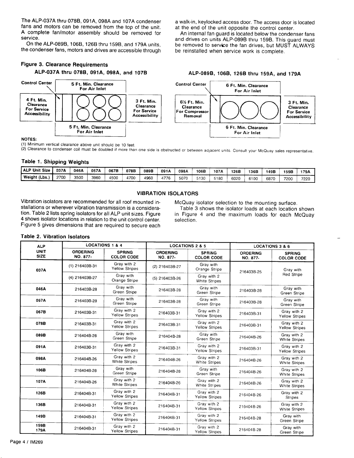
The clearance requirements for these units are given in
Figure 3.
SERVICE ACCESS
Each end of the unit must be accessible after installation for
periodic service work. Compressors, filter-driers, and manual
liquid line shutoff valves are accessible from the control center
end of the unit through removable access panels on unit sizes
089,106, and 126 through 179 and hinged side access doors
on unit sizes 037 through 078, 091, 098 and 107. All opera-
tional, safety, and starting controls are located in the unit con-
trol center. Capped connections for field service gauges are
also located inside these enclosures.
CAUTION: Disconnect all power
to
the unit while servicing
condenser fan drives.
MUST
UiE
THESE RIGGING
HOLES FOR ALP-0898 THRU
159B. (NOTE CONTROL BOX
LOCATION.)
lM269 I Page 3


REFRIGERANT PIPING
GENERAL
McQuay type ALP condensing units are adaptable to either
chilled water or air handling air conditioning applications, The
only restriction on applications is that the evaporator be
selected for a system using refrigerant 22.
EVAPORATOR ABOVE CONDENSING UNIT
Figure 6 shows an installation where the evaporator is in-
stalled above the condensing unit. It is shown for an air han-
dling installation but all components shown are recommended
for chilled water installations, except that a refrigerant
distributor is not usually required for shell-and-tube
evaporators.
EVAPORATOR BELOW CONDENSING UNIT
Figure 7 shows an installation where the evaporator is in-
stalled below the condensing unit. It is shown for an air
han-
Figure 6. Evaporator Above Condensing Unit Figure 7. Evaporator Below Condensing Unit
dling installation, but all components shown are recom-
mended for chilled water installations except that a refrigerant
distributor is not usually required for shell-and-tube
evaporators. Note that a double suction riser is shown for this
arrangement.
Risers “A +
B”
are sized so that their combined
cross-
sectional Internal area will allow full load unit operation without
excessive pressure drop (see notes, Table 4). Riser
“B”
is
sized to provide adequate suction gas velocity for proper oil
return at minimum load conditions. This riser becomes ef-
fective only when the trap shown in riser “A” fills itself with
oil. It should be emphasized that the trap shown in riser “A”
should be designed to contain a minimum internal volume
to keep the total system oil requirements at a minimum. Table
4 gives recommended line sizes for both single and double
suction lines and for liquid lines.
a
b
d”
e
f
A&:
Filter-drer
Solenoid valve
Slghtglasslmolsture indicator
Thermal
expansion
valve
Suction
Ime.
pttched
toward compressor
Liquid
line
Vlbratton
absorber
Double suction riser (see Note 3)
NOTES:
AIR FLOW
1.
Piping
shown
IS
for one circut; second
clrcult
IS
slmllar
2. All
pIping
and pIpIng components are by others
3. Trap for double
suction
riser
should be as small
in
the
horizontal
dlwctlon as ilttlngs
WIII
allow
REFRIGERANT PIPING CONNECTIONS
Refrigerant piping connections must be made at the control
center end of the unit. Suction and liquid lines should be
routed through the compressor end access panels on units
ALP-089B,
106B,
1268 thru 1598, and
179A
and out the
bot-
tom through the side access panels above the compressor
side access door on units ALP-037A thru
078B,091A,
098A
and 107A. When piping, allow room for mounting the
discon-
nect
on this same access panel. Figure 8 gives connection
locations and sizes for all ALP models.
LIQUID LINE COMPONENTS
McQuay has available a “Liquid Line Accessory Kit” for each
ALP unit size. Components selected for these kits were
selected on the basis of a total combined pressure drop of
7 psi (includes 100 ft. of tubing). Table 5 shows the ordering
number to be used for each ALP unit size. The components
in these kits are:
1.
2.
3.
4.
5.
Page 6
/
lM269
Replaceable core type filter-driers.
Filter-drier core elements.
Refrigerant solenoid valves.
Refrigerant sightglass/moisture indicators.
Expansion valves (one per circuit).


Figure 18. ALP-089B,
106B,
126B thru
159A,
&
179A
Control Center Layout
Power into unit
Recommended
field mounted
disconnect
switch
SEQUENCE OF OPERATION
For ALP-037A thru 0788, 091A, 098A
&
107A Units:
The components for a two-compressor unit, models
ALP-046A,
057A,
0678,
078B,
091A,
098A and
107A
are
given in parentheses (
).
The following sequence of operation is for ALP
SEASON-
CON air cooled condensing unit operation. With control cir-
cuit power on, control stop switch
S1
closed, and manual
pumpdown
switch
PS1
(PS2) closed (“auto” position), 115
volt power is applied through control circuit fuse
F1
to the
compressor crankcase heater
HTR1
(HTR2).
When the remote time clock contacts are closed, the flow
switch contacts are closed (chiller applications) and the
manual shutdown switch is on; then relay
R11
is energized,
closing contacts 4 through 6 and 7 through 9. If high pressure
control HP1
(HP2),
motor protector
MP1
(MP2) and oil
pressure control
OP1
(OP2) do not sense an alarm condi-
tion, then the thermostat will energize. The unit will operate
automatically in response to the thermostat.
On a call for cooling,
TC1,
stage 1, energizes liquid line
solenoid
SV1,
opening the valve and allowing refrigerant to
flow into the evaporator. As refrigerant pressure builds up,
low pressure control
LP1
closes to energize compressor
con-
tactor Ml, starting the compressor.
LP1
also energizes con-
denser fan motor 11 and condenser fan motor controls PC1 2,
TC13, and TC14
(TC14
on models ALP-037 067 and 078).
On two-compressor units, if additional stages of cooling are
required, temperature control thermostat
TC1
energizes li-
quid line solenoid valve SV2 after time delay relay TD1 1 has
sequenced closed, to initiate the same starting sequence in
refrigerant circuit number 2.
On units with compressor unloading, if additional stages
of cooling are required, the unloader
U1
(U2) is de-energized
and the compressor is loaded.
For
ALP-089B,
106B,
1268 thru 1598,
&
107A Units
The following sequence of operation is typical for ALP
SEASONCON air cooled condensing unit operation. It is writ-
ten for a four-compressor unit. Components referred to in the
sequence, but not used in a three-compressor unit are HTR3,
Page 18
/
lM269
MP3, R7, TD12, M3 and M7.
With the control circuit power on, control stop switch Sl
closed, and manual
pumpdown
switches PS1 and PS2
closed (“auto” position), 115 volt power is applied through
control circuit fuse Fl to the compressor crankcase heaters
HTR1 and HTR4 and, if safety contacts HP1 and HP2 are
closed, then power is supplied to low pressure switches
LP1
and LP2.
When the remote time clock or manual shutdown switch
turns on, a pair of contacts close in the thermostatic circuit.
If all safeties (HP1 and HP2,
OP1
through OP4 and
MP1
through MP4) do not sense an alarm condition, then safety
relays
R5,
R7,
R6 and
R8
are energized. Power is then sup-
plied to the thermostat
TC1
and the unit will operate
automatically in response to TC1.
On a demand for cooling, the unit thermostat energizes
liquid line solenoid
SV1,
opening the valve and allowing
refrigerant to flow into the evaporator. As refrigerant pressure
builds up, low pressure control
LP1
closes, energizing com-
pressor contactor Ml, starting the compressor.
LP1
also
energizes
R9
which in turn provides power to fan motor
con-
tactors Ml
1,
Ml2 and M13. A second contact on
R9
shuts
out TD15, opening up TD15. If
LP1
opens, cutting power to
R9,
then compressors 1 and 3 cannot be started until TD15
times out and energizes safety relays
R5
and R7.
NOTE: The new motor protectors have a two-minute time
delay. When power is interrupted to terminals 3 and 4 of any
motor protector, the MP contacts across terminals 1 and 2
will not close for two minutes.
If additional stages of cooling are required, the thermostat
energizes liquid line solenoid valve SV2 after time delay relay
TD11
has sequenced closed, to initiate the same starting se-
quence in refrigerant circuit number 2.
If additional cooling is still required, the third and fourth
stages of the thermostat energize the third and fourth com-
pressors after time delay relays TD12 and TD13 have se-
quenced closed.


This manual suits for next models
14
Table of contents
Other McQuay Heat Pump manuals

McQuay
McQuay MHC Standard Range Instruction Manual

McQuay
McQuay Templifier Installation and user guide

McQuay
McQuay ACZ 010A User manual

McQuay
McQuay MWH011B User manual

McQuay
McQuay WH 12B User manual

McQuay
McQuay MWSC 010 Series User manual

McQuay
McQuay FDD Series Instruction Manual

McQuay
McQuay MVCU 025 A User manual

McQuay
McQuay WDA series User manual

McQuay
McQuay Incremental MQT Series Instruction Manual