MD Juniper User manual

MD-001 Juniper User Manual
05/11/22, manual 0.0.5, firmware 0.1.3

About this document
This document is a preliminary outline of the general operation of MD-001 Juniper, it
is not complete and will be updated overtime. It is important to understand that MD-
001 Juniper is in beta, meaning that further features and bugs will be fixed overtime
in order to constantly improve the product and end user experience and this will cause
the contents of this manual to change. For this reason this document cannot be
considered absolute and complete.
What is Juniper?
Juniper is a clocked LFO, modulator, looper, quantiser and general CV mangler. Juniper
is great for accurate clocking, generating strange and wonderful waveforms, quantizing
values, acting as CV manipulator for input signals and for performative CV looping.
All of these features exist on all 8 channels independently.
Juniper provides a utilitarian interface, allowing you to fine tune and dial in
waveforms, or you can dive deep and create mind bending relationships between
channels, often leading to experimental results - its really up to you how you want to
use it.
While Juniper can do quite a number of tasks, it was not designed to be an audio rate
oscillator or sampler (despite it being able to hit audio rates) - perhaps in the
future this could be a goal but for now Junipers primary function is CV.
Features
8 high resolution 16-bit output channels
3 high resolution 16-bit CV inputs and 1 GATE (clock) input
Per channel bipolar (-5V to +5V) and unipolar modes (0V to +5V)
Multiple output waveforms: Sine, square, triangle, sawtooth, exponential,
random, CV inputs
Powerful modulation matrix with modulation sources including all 8 internal
channels and 3 CV inputs
All waveform parameters can be individually modulated
8 individual CV recorders quantized to the beat, streaming directly to the
SDCard for large loop durations
V/Oct quantization
OLED display @ 60Hz with oscilloscope
Low clock drift profile
Micro SD card for firmware updates, data streaming and feature development
Physical specifications
Width: 8 HP (40.3mm)
Height: 128.5mm
Depth: 36mm
Power: 33mA @ -12V, 160mV @ 12V

Interface
Junipers interface was designed for it to be placed in a controller case, with the
buttons more accessible allowing for increased immediacy. The top row of input jacks
are inputs and the second and third rows are output jacks. The output jacks are
indexed from left to right. There are two universal buttons, the SELECT and
clickable ROTARY ENCODER buttons and 8 channel / parameter LED buttons. The LED
buttons illuminosity show that given channels instantaneous signal value, the LED
illuminates from 0% to 100% for -5V to 5V and 0V to 5V for bipolar and unipolar
channel modes respectively.

Controls
The following table represents controls for the primary channel screen:
Buttons Function
ROTATE ENCODER Adjust Selected Parameter
PRESS ENCODER Enter Parameter Settings (Modulation or otherwise)
FRQ Select Frequency Parameter
WAV Select Waveform Parameter
AMP Select Amplitude Parameter
MOR Select Morph Parameter
PHA Select Phase Parameter
OFF Select Offset Parameter
A Select A Parameter
B Select B Parameter
HOLD A + ROTATE ENCODER Change Custom A Parameter
HOLD B + ROTATE ENCODER Change Custom B Parameter
SELECT* + A (1) Select Channel 1
SELECT* + B (2) Select Channel 2
SELECT* + WAV (3) Select Channel 3
SELECT* + FRQ (4) Select Channel 4
SELECT* + AMP (5) Select Channel 5
SELECT* + MOR (6) Select Channel 6
SELECT* + PHA (7) Select Channel 7
SELECT* + OFF (8) Select Channel 8
HOLD SELECT + PRESS ENCODER Enter Global Settings
DOUBLE TAP SELECT Enter Channel Settings
*: TAP or HOLD
The following table represents controls for general navigation:
Buttons Function
ROTATE ENCODER Adjust Selected Value
PRESS ENCODER Select Value / Confirm Value
SELECT Escape or Back

Parameter Guide
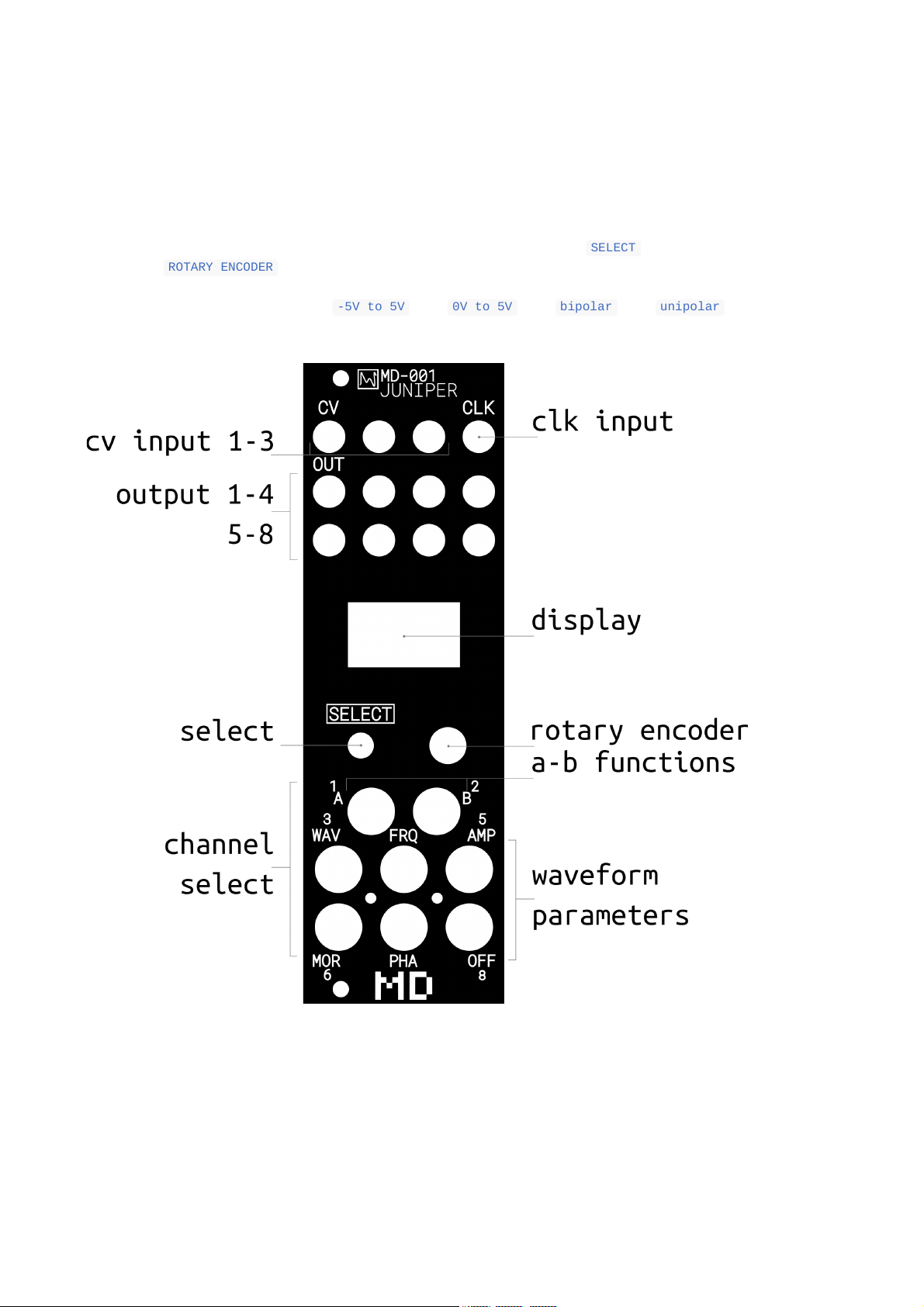
Parameters are building blocks of the waveform generation and manipulation, they can
be accessed by pressing one of the parameter buttons, e.g. "FRQ" while on the main
channel screen. There are (currently) 3 "A-B" parameters that can be accessed, to
adjust which "A-B" parameter is displayable hold "A" or "B" and rotate the encoder.
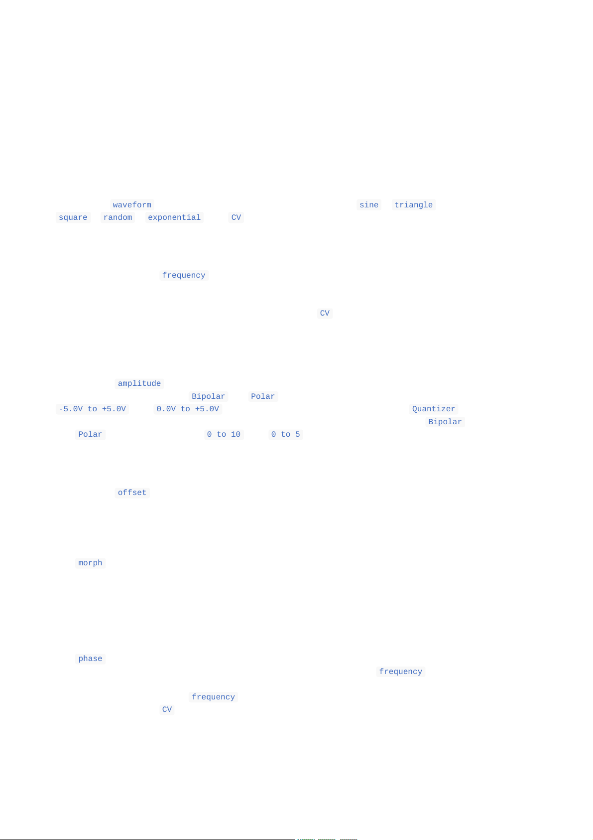
Waveform
Adjust the waveform of the given channel. Waveforms include sine , triangle ,
square , random , exponential and CV . The waveform setting can be modulated with
both internal and external sources.
Frequency
Adjusts the periodic frequency of the given channel. Frequencies are relative to the
global BPM of the device. The frequency setting can be modulated with both internal
and external sources. When frequency modulation is active there is no guarantee that
the frequency is synchronized with the BPM. When the CV waveform is selected, there
is no periodic or frequency component of the waveform, as this is a representation of
the input signal.
Amplitude
Adjusts the amplitude of a given channel. The full-scale of the output has an
amplitude of 100%. When in Bipolar or Polar modes an amplitude of 100% represents a
-5.0V to +5.0V and 0.0V to +5.0V voltage range respectively. When the Quantizer is
active the representation changes from percentage to octaves, in this case Bipolar
and Polar modes represents a 0 to 10 and 0 to 5 octave range respectively. The
amplitude setting can be modulated with both internal and external sources.
Offset
Adjusts the offset of a given channel. At a value of 50% there is no offset being
applied, e.g. the waveform is generated within the middle of the amplitude range. The
offset setting can be modulated with both internal and external sources.
Morph
The morph function varies depending on the waveform and adjusts the waveform shape.
For triangle a ramp or sawtooth can be achieved, for square wave the duty cycle is
adjusted. For the CV waveform, the morph parameter mixes between the 3 different input
channels where 0%, 50% and 100% represents CV input 1, 2 and 3 respectively. The morph
setting can be modulated with both internal and external sources.
Phase
The phase parameter allows periodic waveforms to be phase locked to varying degrees,
or not locked at all. When the phase is locked any adjustment to frequency will cause
the phase to be recalculated (this can cause visual discontinuities in the waveform
which is normal). When the frequency is modulated the phase locking is disabled
altogether. When the CV waveform is selected, there is no periodic or phase
component of the waveform, as this is a representation of the input signal.

Recorder
A recorder is available for each channel, streaming directly to the SDCard allowing
for very large record durations. There are three states, Stop Rec and Play .
Currently there is a 255 bar limitation, but work is being done to make the
recorder dynamically set the bar length. Stay tuned.
Recordings are time-quantized to bar within a 4/4 time signature. The total record
duration is determined by the BPM at the initial moment of recording, any further
adjustments of BPM are ignored by the recorder. It is possible to manually trigger the
Record state or from either an internal or external source. When configuring the
recorder, the following is available:
Number of bars as given by a 4/4 time signature
Play Trig, which will begin or stop playback
Record Trig, which can begin or stop recording
Stop mode
FAL: Falling stop mode edge, e.g. you begin a recording and wish to stop
it on the falling edge of the Record Trig source
RIS: Rising stop mode edge. e.g. you begin playback and wish to stop it
by providing a rising edge of the Playback Trig source
Playback mode
CON: Continuous playback mode, will automatically begin playback after
recording and continually loop playback until stopped
SGL: Single shot mode, will play only when requested and only once,
after playback is complete the recorder returns to a Stopped state
Sample and Hold
The sample and hold (S&H) allows the user to take the current value of an output
channel and hold it for a desired period of time. There are two selectable values:
Release where no S&H action will occur and Hold where the S&H is active. It is
possible to manually trigger the S&H or trigger it from either an internal or external
source.
Key
The key parameter will v/oct quantize the instantaneous value to a given note. When
quantization is active, the current quantization value is displayed. Additionally the
amplitude parameter will be displayed in octaves.

Settings
There are 3 setting menus, all accessible with minimal menu diving, they are
Parameter Settings , Channel Settings and Global Settings .
Parameter Settings
Parameter settings affect the selected parameter only. Usually these are modulation
settings, trigger settings or other related settings to how the parameter affects
waveform generation. To access a parameters settings, go to the desired parameter on
the desired channel and then simply press the ROTARY ENCODER .
Modulation
As the standard modulation settings are the most common, these are described below.
For parameters with no modulation settings (e.g. the Recorder, or S&H) see their
description directly in the Parameter Guide.
Modulation
Function Description
Source Sets the modulation source, this can be any of the internal or
external channels.
Type LINEAR or EXPONENTIAL
Index A percentage value between 0 and 100, higher indicates more
modulation
Offset Offsets the incoming source signal from -50% to +50%.
Channel Settings
Channel settings affect individual channels only. To access the channel settings, go
to a desired channel and then double tap the SELECT button. The current channel
settings include:
Function Description
Mute Mutes the channel
Polarity Toggles between Bipolar and Polar modes. Note: during recording or
playback this option is disabled.
Record
Stop Mode Adjusts the channels Record Stop Mode behaviour
Clear Mods Removes all modulations for a channel
Clear Clears the channel and resets it back to the default state
Global Settings
Global settings affect the entire operation of the device, irrespective of channel.
Global settings are accessed by holding SELECT and pressing the ROTARY ENCODER on
the main channel screen. The current global settings include:

Function Description
Run Starts and stops the signal generation
BPM Sets the BPM
PPQN Sets the pulses per quarter note for external BPM synchronization
CLK Mode Configures the CLK input to either BPM or GATE ONLY. When configured
for GATE ONLY, the CLK input has no affect on the BPM.
RUN
Trigger
Will start the device either manually via the Run option, or externally
via a trigger transient
Run Edge Configure if the run trigger should start on a rising, falling or
rising & falling edge
LEDS Sets the button LED brightness
OLED Sets the OLED display brightness
Wipe
Mods
Wipes all modulation settings from the device, restoring them to
default
Wipe
Channels Wipes all channels from the device, restoring them to default
Wipe All Wipes all state from the SD Card and reboots the device. Calibration
data is retained.

Maintenance
Firmware updates
Firmware updates will occur periodically to provide further features and bug fixes to
the device. Firmware can be updated by downloading one of the release binaries found
at www.mnemonicdevices.io/juniper. Firmware is upgraded by copying the binary .bin
file to the FAT32 formatted microsd card of the device and naming the file fw.bin .
On power-up hold the PHASE/CH7 button, the boot-loader of the device will then begin
the flash procedure. Release the PHASE/CH7 button and wait until the device finishes
flashing the firmware. Once it completes it will reboot the device and the newly
installed firmware will run. Verify the procedure worked by checking the version
number on the boot-up screen.
SDCard requirements
The micro SD card must be formatted with FAT32 and use Master Boot Record (MBR) .
Calibration
This device has various analog circuitry that affects the inputs and outputs of the
device. Analog circuitry is susceptible to environmental factors which can cause
changes in electrical properties, therefore this device requires occasional tuning.
In order to calibrate the device, a multimeter of good accuracy is required. mnemonic
devices recommends the Fluke 101 multimeter. Its easiest to connect the multimeter
using alligator clips directly to a 3.5mm mono patch cable.
It is important to calibrate the device as accurately as possible, take your time
to ensure the multimeter has stabilized the reading before moving to the next
step.
To begin the calibration procedure, on boot-up hold the OFFSET/CH8 button. The
calibration "wizard" will begin.
1. Repeat the following steps 2-4 for all 8 output channels
2. Plug the multi-meter connected patch cable into output N
3. Calibrate output N, the -5.0V reading
4. Calibrate output N, the +5.0V reading
5. Repeat the following steps 6-8 for all 3 CV inputs
6. Plug a patch cable from output 1 into input Y
7. Begin sampling input N, the first reading
8. Begin sampling input N, the second reading
Then follow the prompts to store the calibration data and then reboot. Wait for the
device to reboot.

Support
For all issues, software or hardware, or maybe you have a suggestion or a feature
idea, please contact me directly at [email protected].
Software Faults
Sometimes unexpected software issues can occur - In the event of a crash or fault, a
log file "dump.txt" will be written to the SD Card. This log file will have useful
information for finding the problem. Please send an email to
[email protected] with this log file, along with all other configuration
files on the SD card and a description of what you were doing to produce the bug.
If the bug persists upon reboot, its likely that the configuration files stored on the
SD card are re-triggering the issue. You can safely delete the files on the SD card,
this will clean the state out and the device should then be able to boot normally.
Safety
The following must be adhered to in order for safety and compliance of operation.
1. Do not attempt to load unverified firmware or otherwise to the device.
2. This device is only intended for use within a compliant Eurorack housing with
sufficient power supply requirements.
3. This device is not intended for operation in extreme environmental conditions.
4. Do not expose the device to any liquid and store within a dry place out of
direct sunlight.
5. This device must only be transported with the supplied packaging, for repair or
otherwise.
6. Do not use this device if it is damaged.
7. Dispose of this device only into e-waste to help protect the environment.
8. Only use a quality micro SD Card from a reliable manufacturer, ideally the one
supplied with the unit. The following SD Card manufacturers are tested and
verified: Intenso and Sandisk
--
Reproduction, distribution or commercial use in any form is prohibited and requires
written permission from mnemonic devices.
mnemonic devices reserves the right to change the contents within this document at any
time.
This manual suits for next models
1
Table of contents
Other MD Recording Equipment manuals