Hubbell GAI-Tronics H96032B User manual

Pub. 42004-283
GAI-Tronics Corporation P.O. Box 1060, Reading, PA 19607-1060 USA
610-777-1374 n800-492-1212 nFax: 610-775-6540
VISIT WWW.GAI-TRONICS.COM FOR PRODUCT LITERATURE AND MANUALS
GAI-TRONICS® CORPORATION
A HUBBELL COMPANY
Model H96032B
Telephone Interface
TABLE OF CONTENTS
CONFIDENTIALITY NOTICE.......................................................................................................................... 1
INTRODUCTION................................................................................................................................................ 1
INSTALLATION................................................................................................................................................. 3
WIRING INSTRUCTIONS ....................................................................................................................................... 3
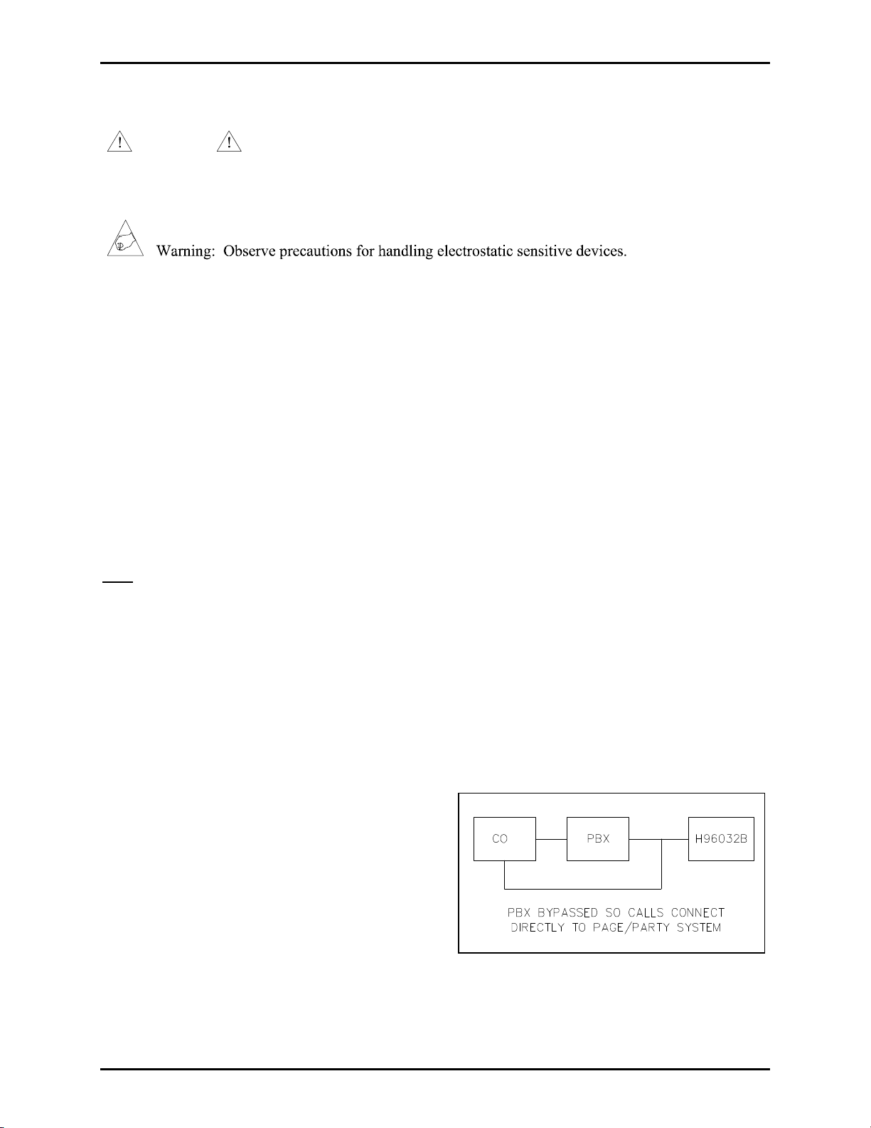
TELEPHONE LINE CONNECTIONS.......................................................................................................................... 3
INPUT POWER ..................................................................................................................................................... 4
PUBLIC ADDRESS SYSTEM CONNECTIONS ............................................................................................................ 4
REMOTE CONNECTIONS....................................................................................................................................... 4
PROGRAMMING PARAMETERS.................................................................................................................... 6
DAY AND NIGHT MODE....................................................................................................................................... 6
SELECTING AN INCOMING ACCESS METHOD......................................................................................................... 6
Voice Access Method..................................................................................................................................... 6
Programmable Parameters:......................................................................................................................................... 6
Ring Access Method ...................................................................................................................................... 7
Selective Access Method................................................................................................................................ 7
Programmable Parameters:......................................................................................................................................... 7
Manual Access Method.................................................................................................................................. 7
TERMINATING CALLS.......................................................................................................................................... 8
NUMBER OF INCOMING RINGS.............................................................................................................................. 8
HANG-UP DELAY ................................................................................................................................................ 8
INTERNAL/EXTERNAL DAY/NIGHT SWITCH.......................................................................................................... 8
PROGRAMMING PROCEDURE...................................................................................................................... 9
GENERAL INSTRUCTIONS..................................................................................................................................... 9
ENTERING AND EXITING THE PROGRAMMING MODE............................................................................................. 9
PROGRAMMING EXAMPLE: DAY MODE ............................................................................................................. 10
PROGRAMMING EXAMPLE: NIGHT MODE .......................................................................................................... 10
PROGRAMMING TABLE...................................................................................................................................... 11
ADJUSTMENTS................................................................................................................................................ 13
PROGRAMMING SUMMARY CHART..................................................................................................................... 13
SPECIFICATIONS............................................................................................................................................ 14
REPLACEMENT PART......................................................................................................................................... 14

Pub. 42004-283
GAI-Tronics Corporation P.O. Box 1060, Reading, PA 19607-1060 USA
610-777-1374 n800-492-1212 nFax: 610-775-6540
VISIT WWW.GAI-TRONICS.COM FOR PRODUCT LITERATURE AND MANUALS
Model H96032B
Telephone Interface
Confidentiality Notice
This manual is provided solely as an operational, installation, and maintenance guide and contains sensitive
business and technical information that is confidential and proprietary to GAI-Tronics. GAI-Tronics retains
all intellectual property and other rights in or to the information contained herein, and such information may
only be used in connection with the operation of your GAI-Tronics product or system. This manual may not
be disclosed in any form, in whole or in part, directly or indirectly, to any third party.
Introduction
The rack-mounted Model H96032B Telephone Interface provides a communication link between a public
address system manufactured by GAI-Tronics and a public or private telephone system. The telephone
interface can be used within a Page/Party®or a SmartSeries®public address system.
The telephone interface allows individuals to access the page line and the party line of the public address
system while using a standard telephone. The programming options of this interface make the unit
extremely versatile.
Because the demands on your communication system may vary from the day shift to the night shift, this
interface can be configured for two independent sets of operating parameters—day mode and night mode.
The method used to receive incoming telephone calls can be configured differently for each mode.
Incoming telephone calls can access the public-address system using one of four incoming access methods:
voice access, ring access, selective access, or manual access. The incoming access method selected
determines the way the incoming call accesses the public-address system. For example, the telephone
interface can be configured to transfer the call directly to the designated page line or require the
intervention of a switchboard operator.
Review the programming options listed in this manual to identify the optimal configuration for your
facility.

Page: 2of 14
Model H96032B Telephone Interface 42004-283
d:\standard ioms - current release\42004 instr. manuals\42004-283.doc
7/98
NOTE The Model H96032B is not registered with the Federal Communications Commission
(FCC). However, the unit is designed to comply with all applicable FCC requirements. As the owner of
this device, you must provide the following information to the operating telephone company before
connecting or disconnecting the device:
•Notice of your intent to use privately-owned telephone equipment
•The telephone number(s) to be used
•Model: GAI-Tronics Model H96032B Programmable Telephone Interface
•Ringer Equivalence Number (REN): 0.4B
WARNING This equipment generates, uses, and can radiate radio frequency energy and if not
installed and used in accordance with the instruction manual, may cause interference to radio
communications. Operation of the equipment in a residential area is likely to cause interference. If
interference occurs, the user is required to take whatever measures are necessary to correct this
interference.
Figure 1. Telephone Interface —Top View

Page: 3of 14
Model H96032B Telephone Interface 42004-283
d:\standard ioms - current release\42004 instr. manuals\42004-283.doc
7/98
Installation
WARNING Disconnect power before installing the telephone interface. This device can
present a 115/230 V ac shock hazard. Please use care when handling this device. Be sure that the ac
power is not connected during wiring.
The H96032B must be installed in an environment within the temperature range of 0 ºC to +70 ºC
(+32 ºF to +158 ºF). Do not install the H96032B near equipment that can cause excessive electrostatic, or
electromagnetic interference (EMI) or radio frequency interference (RFI).
Mount the Model H96032B Telephone Interface in a standard 19-inch EIA equipment rack. The telephone
interface occupies 2U (3.5 inches) of vertical rack space. Depth clearance behind the mounting rails should
be at least 12 to 14 inches for wiring.
In addition to the aforementioned mounting requirement, the following should be considered:
•A telephone line from the telephone company or PBX should exist.
•A Page/Party®station should be in proximity to permit ease of audio level adjustments while listening
to the Page/Party®station handset. The distance from the H96032B to one Page/Party®station should
be such that someone can adjust the controls on the H96032B while listening to the handset of the
station.
Note: If the system does not contain any handset stations, contact the GAI-Tronics Field Service
Department for instructions at 800-492-1212 inside the USA or 610-777-1374 outside the USA, 8 a.m. to
5:00 p.m., Monday through Friday, Eastern Standard Time (EST).
Wiring Instructions
1. Run the power cord to the ac power receptacle, connect the cord.
2. Run all signal, and control lines if used, to the proper terminals as shown in Figure 1.
Telephone Line Connections
The H96032B should be connected to either the
Central Office (CO) line from the telephone company
or to a PBX at the 2-point terminal block provided at
the rear of the unit. If a telephone line does not exist,
contact your telephone company if a CO line needs to
be installed or extended.
The connection outlined in Figure 2is recommended
because it allows the use of all the available types of
incoming modes. If the call from the CO is to be
directly connected to the interface for the public-
address system, use the bypass feature available on the PBX.
Figure 2. Telephone Connections

Page: 4of 14
Model H96032B Telephone Interface 42004-283
d:\standard ioms - current release\42004 instr. manuals\42004-283.doc
7/98
Input Power
This unit can be powered by 115 V ac, 230 V ac (50/60 Hz) or 24 V dc. A power selector switch is
located on the power supply printed circuit board assembly (PCBA) and includes settings for 115 V ac
(default) and 230 V ac. For dc power applications, either the 115 V ac setting or the 230 V ac setting may
be used.
Each power input is fuse protected. The two fuses are located on the top of the power supply shield. Both
fuses are rated at 0.5 amp. See Figure 1.
AC Power. For 115 V ac applications, use the power cord provided with the unit. For 230 V ac
applications, a Belden part number 17566 power cord must be used in place of the power cord supplied
with the unit. Set the power selector switch on the power supply PCBA to the desired voltage setting.
DC Power. For dc applications, a battery or a dc power supply/battery charger can be used. The power
source should be UL approved and must be capable of providing 500 mA dc @ 21-28 V. Terminations for
the dc input are located at the rear of the unit, adjacent to the ac power connector. Terminal 17 is the
positive terminal, terminal 18 is the negative terminal, and terminal 19 is GROUND. Terminal 19 should
be connected to the earth ground for safety.
Public Address System Connections
Connect the telephone interface needs to the
page line and the party line of the public
address system. See Figure 3. Page line
connections are made at terminals 3 and 4, and
party line connections are made at terminals 5
and 6.
The telephone interface can only be connected
to one party line; therefore, in a multi-party
system, one of the party lines must be
designated for use with the telephone interface.
Note:The 33-ohm line balance resistor must be removed from the designated party line of the Page/Party®
or SmartSeries®system. The resistor is generally located in a separate assembly called a line balance
assembly network. Only the line balance resistor for the designated party line should be disconnected.
Remote Connections
The ACCESS, RESET, and DAY/NIGHT switches on the H96032B’s front cover can be connected and
subsequently activated from a remote location. This allows the telephone interface to be controlled from a
remote location.
This may be useful if the telephone interface is installed in a location separate from the switchboard or
primary user. The ACCESS switch manually connects the public address system and the outside telephone
line. The RESET switch can be used to disconnect calls. The DAY/NIGHT switch is used to switch the unit
between the two modes of operation.
Figure
3
. Connections

Page: 5of 14
Model H96032B Telephone Interface 42004-283
d:\standard ioms - current release\42004 instr. manuals\42004-283.doc
7/98
Terminations for the ACCESS, RESET and DAY/NIGHT switches are connected with reference to the COM
terminals (9 or 10). Terminal 7 and COM are used for the remote ACCESS switch; terminal 8 and COM
are used for the remote RESET switch; terminal 9 and COM are used for the remote DAY/NIGHT switch.
The ACCESS and RESET switches should be normally open (N.O.) momentary switches. The DAY/NIGHT
switch must be a maintained switch, typically a single pole, single-throw (SPST) toggle switch which can
be marked to show the operator which mode has been selected. If using an automatic timing system, the
relay contact must be closed during DAY mode and open during NIGHT mode.
Note: Terminals 7, 8, and 9 are common to all switches; therefore, a four-conductor cable may be used to
connect all three remote switches.
In addition to the functions described above, the telephone interface is equipped with dry contact PAGE
CONTROL output and two additional reset functions. The additional reset functions are Page
Reset/Disconnect (PG RST/DISC) and Page Reset/Disconnect External Power (PG RST/DISC EXT PWR).
Terminations for these functions are at terminals 11 through 16. Each is described below:
Page Control. This normally open dry contact output is accessed at terminals 15 and 16. This contact is
active (closed) while the telephone call is connected to the page line (broadcasting a public address
message). At the end of the page interval, the contact reverts back to its N.O. position. The output contact
is rated to 30 V dc @ 1 A.
Page Reset/Disconnect (PG RST/DISC). This input at terminal 11 is worked via an external dry contact
against one of the COM terminals. Activating this input while the telephone call is connected to the page
line resets the telephone interface and disconnects the call. After the telephone interface has switched to
party mode, this disconnect input is disabled.
Page Reset/Disconnect External Power (PG RST/DISC EXT PWR). This input at terminals 13 and 14
requires a 12 V dc @ 20 mA source power to activate. Proper polarity must be observed when making
connections to these terminals. Activating this input while the telephone call is connected to the page line
resets the telephone interface and disconnects the call. After the telephone interface has switched to party
mode, this disconnect input is disabled.
Figure 4. Front View of H96032B

Page: 6of 14
Model H96032B Telephone Interface 42004-283
d:\standard ioms - current release\42004 instr. manuals\42004-283.doc
7/98
Programming Parameters
Day and Night Mode
The two modes of operation are Day mode and
Night mode, and each has separate parameters
and separate programming procedures.
Day mode parameters must be programmed
with the H96032B in DAY mode, and Night mode parameters must be programmed with the unit in NIGHT
mode. The mode is chosen by toggling the DAY/NIGHT switch on the front panel. The LEDs on the front
panel indicate which mode the unit is in. See table.
Selecting an Incoming Access Method
The incoming access method can be different for the day mode and night modes. Four methods are
available: voice access, ring access, selective access, or manual access.
Incoming calls can be answered in the following ways:
1If the designated party line is idle (with all stations on designated party line on-hook), the call is
answered when any station on the designated party line goes off-hook. If the party line is in use, all the
stations on the party line must be on-hook before the call can be answered;
2In the Voice Access mode, the H96032B can be programmed to automatically connect to the
designated party line, even if the party line is in use, after a programmed number of rings and a preset
paging period has elapsed. See the programming instructions for further details.
The Model H96032 is factory-programmed for the Voice Access method selected. To change the incoming
access method or to change the programmable parameters of the incoming access method, refer to page 11
of the Programming Table for instructions.
Voice Access Method
Using the Voice Access method, incoming calls are automatically answered (after the programmed number
of rings) and connected to the page line for voice paging. The H96032B sounds a tone over the system
speakers indicating that the upcoming page is from a telephone caller and not a Page/Party®station user.
Three programmable parameters are available with the Voice Access method.
Programmable Parameters:
•Page duration (0 to 99 seconds)—the amount of time the caller has to make a page;
•The maximum number of seconds the call will be held before it is disconnected if not answered
(0 to 99 seconds);
•Enabling or disabling the auto-connect mode. If the unit is programmed to auto-connect, the caller is
directly connected to the designated party line—regardless of the partly line status.
Note: If the H96032B is connected to an outside line, the Voice Access method may not be the best
selection because wrong numbers or crank calls could access and disrupt your communications system.
Day Mode LED Night Mode LED
In Use Constant On Flashing, mostly on
Not in Use Constant Off Flashing, mostly off

Page: 7of 14
Model H96032B Telephone Interface 42004-283
d:\standard ioms - current release\42004 instr. manuals\42004-283.doc
7/98
Ring Access Method
Using the Ring Access method, a ring-tone is generated on the page line to alert facility personnel of an
incoming telephone call. Facility personnel can answer the call by taking a station handset off-hook and
selecting the designated party line.
Note:The incoming telephone call rings on the page line after the programmed number of incoming rings.
Selective Access Method
The Selective Access method is recommended for applications where the H96032B is connected to an
outside line. The Selective Access method eliminates disturbances from nuisance calls and wrong numbers,
because the telephone caller must dial the correct two-digit code to gain access to the system. The Selective
Access method is the most flexible option because it can provide the same access options available with the
Voice Access method and the Ring Access method.
Using this method, the incoming call is automatically answered by the telephone interface. The telephone
interface generates an audible signal that is heard by the calling party. The signal indicates the status of the
party line: one beep indicates that the party line is not in use and three beeps indicates that the party line is
in use.
The telephone caller has 30 seconds to respond and dial a two-digit code (refer to page 12 for programming
instructions). One code accesses the page line (as done in the Voice Access method) and the second code
rings on the page line (as done in the Ring Access method). Five programmable parameters are available
with the Selective Access method:
Programmable Parameters:
•Page duration (0 to 99 seconds)—the amount of time the telephone caller has to make a page;
•The maximum number of seconds the call is held before it is disconnected if not answered
(0 to 99 seconds);
•Enabling or disabling the auto-connect mode. If the unit is programmed to auto-connect, the telephone
caller is directly connected to the designated party line—regardless of the party line status;
•Voice Access code—the single digit code used by the telephone caller to enable voice access;
•Ring Access Code—The single digit code used by the telephone caller to enable ring access.
Manual Access Method
The Manual Access method is ideal for use when the H96032B is connected to a switchboard manned by
an operator. All incoming calls go to the switchboard, and the operator must connect the telephone call to
the Page/Party®system by pressing the ACCESS button on the front cover of the H96032B. The H96032B
is inactive until the operator presses the ACCESS button.

Page: 8of 14
Model H96032B Telephone Interface 42004-283
d:\standard ioms - current release\42004 instr. manuals\42004-283.doc
7/98
Terminating Calls
Calls may be terminated in one of three ways:
1. After a call has been answered, it can be terminated by placing the station on-hook (all GAI-Tronics
stations on the designated party line must be on-hook). When all the stations on the party line are
placed on-hook, the H96032B disconnects from the telephone line after a programmable delay. Refer
to the programming instructions for details.
2. Pressing the RESET on the front panel of the H96032B, or a remote reset button immediately
disconnects the H96032B from the telephone line.
3. If the incoming telephone line is equipped with a loop current disconnect feature, the H96032B is
automatically disconnected from the telephone when the outside calling party hangs up the phone.
Note: The loop current disconnect feature (calling party disconnect) is highly recommended for
systems using the auto-connect feature and systems with a large number of Page/Party®stations.
Number of Incoming Rings
This function sets the number of rings (1 to 9) that the H96032B waits before answering incoming calls. If
the user wants to give the operator a chance to pick up the call before the H96032B responds, the
programmer may want to program a fairly high number of rings.
The number programmed into the unit (0 to 9) sets the delayed number of rings before the unit answers.
For example, if the number 0 is programmed as the delay for the incoming rings, the unit answers after the
first ring (programmed number plus 1). If 4 is programmed, the unit delays 4 rings and answers after the
fifth ring.
Hang-up Delay
This parameter sets the delay time between the time when a Page/Party®station goes on-hook and the call
is disconnected. If the delay is set to zero, the H96032B disconnects incoming calls when the Page/Party®
station goes on-hook. However, if the user needs to make a page while a caller is on the party line in order
to have an additional person join the conversation, the hang-up delay should be set at 15 seconds or higher.
At this setting, the user has 15 seconds to make a page and return on to the page line without the caller
being disconnected.
Internal/External Day/Night Switch
The user must determine if an internal or external (remote) switch will control the Day/Night mode. If the
user plans to operate the Day/Night switch located on the front panel of the H96032B, then internal switch
should be chosen. This momentary switch toggles the unit between day and night modes. The user may
watch the LED located next to the switch to determine the unit mode. Steady-on or steady-off means the
unit is in day mode, and a blinking LED indicates that the unit is in night mode. Refer to Programming,
General Instructions on page 9for details.
To operate the Day/Night mode remotely, the installer should wire a two-position switch, and select the
external switch. This is to ensure that the day and night modes can be marked on the remote switch.

Page: 9of 14
Model H96032B Telephone Interface 42004-283
d:\standard ioms - current release\42004 instr. manuals\42004-283.doc
7/98
Programming Procedure
General Instructions
The Model H96032B Telephone Interface is programmed from a touch-tone (DTMF) telephone. If
programming the unit from an outside line, the public address system must first be accessed by calling the
number to which the interface is connected. A station handset must be taken off-hook and the ACCESS
button on the front cover of the telephone interface must be pushed. Ensure that the station is set to the
designated party line.
Note:If there are no handset stations in the system, contact GAI-Tronics Field Service for Programming
Instructions.
The programmable features of the Model H96032B Telephone Interface allow it to be tailored to different
needs. The unit is shipped from the factory programmed with a set of default parameters, listed on page 13
in the Programming Summary Chart. Read the entire Programming section, record the desired selections
in the column titled User Programming, and then proceed to program the unit. Having all the codes chosen
and recorded will make programming easier.
Entering and Exiting the Programming Mode
1. Place the unit in Day mode by pushing the DAY/NIGHT switch and observing the LED. See the table
on page 6.
2. Dial the telephone number of the H96032B, and access the public-address system.
Note:The unit is set at the factory to answer incoming calls using the Voice Access method that
automatically connects the incoming call to the page line. Therefore, have someone lift the handset of a
station, and set the station to the designated H96032B party line. Then proceed with the programming
instructions.
3. With access to the designated party line, dial #*92 to enter the program mode.
4. In the programming mode, dial the sequence of options recorded in the User Programming column.
Refer to the Programming Table (page 11) for variable definitions.
Note:If the programmer presses too many buttons or attempts to enter an invalid code, it will respond
with a beep in the ear piece.
5. When all programming is finished, enter #* to end the programming session.
6. Place the unit in NIGHT mode, go back to Step 3, and program the unit for NIGHT mode parameters.

Page: 10 of 14
Model H96032B Telephone Interface 42004-283
d:\standard ioms - current release\42004 instr. manuals\42004-283.doc
7/98
The following tables show examples of programming input for both Day mode and Night mode.
Remember that these are only examples and that your programming codes may be different.
Programming Example: Day Mode
Dial Sequence Description
#*92 Put the unit into program mode.
#3007601 Selects Voice Access incoming method; 07 seconds of voice page;
60 seconds to answer the call; auto-connect option enabled
#43 Sets incoming rings to 4
#907 Sets hang up delay to 7 seconds
#10 Sets dialing mode to tone
#81 Sets Day/Night switch for internal operation
#* Ends programming—unit is functional
Programming Example: Night Mode
Dial Sequence Description
#*92 Puts the unit into program mode.
#31 Selects ring access incoming mode
#40 Sets incoming rings to 1
#907 Sets hang up delay to 7 seconds
#* Ends programming—unit is functional

Page: 11 of 14
Model H96032B Telephone Interface 42004-283
d:\standard ioms - current release\42004 instr. manuals\42004-283.doc
7/98
Programming Table
Function Reset Unit to Factory Codes (Default)
Key Sequence # #
Description
(Day Mode)
Voice Access Mode (for incoming calls)
7 second voice page
60 seconds after the page for the call to be answered before disconnection
Auto-connect enabled
4 incoming rings before H96032B enters page mode
7 second hang up delay
Internal Day/Night switch
Description
(Night Mode)
Ring Access Mode (for incoming calls)
1 incoming ring before H96032B generates a ring tone on the page line
7 second hang up delay
Internal Day/Night switch
*Function Select Incoming Call - Voice Access Method
Key Sequence # 3 0 P P M M A
Description If selected, incoming calls are transferred directly to page line.
PP = Number of seconds of voice page (00 to 99)
MM = Number of seconds after a page that the call must be answered (00 to 99) before
the call is disconnected (auto-connect DISABLED). With auto-connected ENABLED,
the call is transferred directly to the designated party line after the page.
A = Set auto-connect option; 1 to enable; 0 to disable
For example, to set a 15-second voice page, a 25-second period after the end of the page
before the call reverts to the auto-connect option, and to enable the auto-connect option,
enter the following code: # 3 0 1 5 2 5 1.
*Function Select Incoming Call - Ring Access Method
Key Sequence # 3 1
Description If selected, incoming call rings are transferred directly to the page line after a
programmed number of rings have elapsed. To answer the call, someone must take a
Page/Party®station off-hook that is on the designated party line.
*Function Select Incoming Call - Manual Access Method
Key Sequence # 3 3
Description If selected, the only way incoming calls can access the Page/Party®system is for a
switchboard operator to take the incoming call and press the ACCESS button on the front
cover of the H96032B. The incoming call is automatically transferred to the designated
party line, provided a station is off-hook on the designated party line.

Page: 12 of 14
Model H96032B Telephone Interface 42004-283
d:\standard ioms - current release\42004 instr. manuals\42004-283.doc
7/98
Programming Table
*Function Select Incoming Call - Selective Access Method
Key Sequence # 3 2 P P M M A X Y
Description If selected, incoming calls receive a coded beep to indicate if the designated party line is
in use. After hearing the coded beeps, the caller can select either Voice Access mode or
Ring Access mode.
PP = Number of seconds of voice page (00 to 99)
MM = Number of seconds after the page that the call must be answered (00 to 99);
if call is not answered, it is terminated
A = Set auto-connect option; 1 to enable; 0 to disable.
X = Access code digit for caller to select Voice Access mode (0 to 9).
Y = Access code digit for caller to select Ring Access mode (0 to 9),
must be different than X..)
For example, to set a 15-second voice page, a 25-second period after the end of the page
before the call reverts to the auto-connect option, to enable the auto-connect option, to set
the code to enter Voice Access Mode at 2 and the code to enter Page Access Mode be 5,
enter the following code: # 3 2 1 5 2 5 1 2 5.
Function Set Number of Incoming Rings
Key Sequence # 4 N
Description This function sets the number of rings that must elapse before the H96032B
acknowledges an incoming call. If an operator is on duty, this function would give him
time to intercept any incoming calls. For example, to set the incoming ring delay at 4
rings, enter the following code: # 4 4. The H96032B then answers the call after the 5th
ring.
Function Set Hang Up Delay
Key Sequence # 9 N N
Description NN is the number of seconds (00 to 99) that elapse after all Page/Party®stations on the
designated party line are on-hook and the outside call is disconnected. As explained
above, this time should not be set to zero in case users want to page during the
conversation. The average time for this delay should be approximately 7 seconds. To
program a 7-second hang-up delay, enter the following code: # 9 0 7.
Function Set DAY/NIGHT Switch (Internal/External)
Key Sequence # 8 X
Description This function sets the method by which the Day and Night modes are selected. If the
Day/Night switch on the front panel is to be used, then Internal should be selected. If the
selection is to be made via a remote switch, then External should be selected. For
example, to select Internal Day/Night switching, enter: # 8 1. To select External
Day/Night switching, enter: # 8 0.
*Select only one of these functions for each mode: one for Day and one for Night mode.

Page: 13 of 14
Model H96032B Telephone Interface 42004-283
d:\standard ioms - current release\42004 instr. manuals\42004-283.doc
7/98
Adjustments
The inside front cover of the Model H96032B contains three potentiometers to adjust audio levels. Use a
small standard screwdriver to adjust the page line level. Before adjustments are made, turn the Party Line
Level potentiometer fully counterclockwise and the Page Line Level potentiometer approximately one-half
of its travel. Use an outside telephone to establish communications through the H96032B with the GAI-
Tronics paging system. When the incoming call is connected to the page line, adjust the Page Line Level
potentiometer until the volume level of the incoming page is approximately equal to a page made within the
system.
After the page level is adjusted, pick up the incoming call at a station near the H96032B. When
communications are established, adjust the Sidetone Adjust potentiometer on the H96032B for minimum
sidetone on the GAI-Tronics station. Sidetone is the amount of signal transmitted from the microphone to
the receiver. To complete this adjustment, blow into the microphone at the GAI-Tronics station while
adjusting the potentiometer on the H96032B for minimum signal in the earpiece of the GAI-Tronics station.
As the potentiometer is adjusted, the signal will decrease (null), then increase.
After the sidetone adjustment is completed, adjust the Party Line Level potentiometer until the level of the
signal from the telephone line is comparable to the level of a signal within the system.
If all adjustments are made properly, pages from the H96032B will be the same volume as pages from a
Page/Party®station. Party line adjustment should be tested from a Page/Party®station. When properly
set, this communication with an outside call will sound like communication with another station.
Programming Summary Chart
Description Factory Setting
(Day Mode) Factory Setting
(Night Mode) User Programming
Day Mode Night Mode
Incoming Call Mode Voice Access Mode Ring Access Mode
Voice Page Duration 7 seconds N/A with unit in Ring
Access Mode
Page to Answer
Duration 60 seconds N/A with unit in Ring
Access Mode
Auto-connect Option Enabled N/A with unit in Ring
Access Mode
Incoming Rings 4 1
Hang Up Delay 7 seconds 7 seconds
Day/Night Switch Internal Internal

Page: 14 of 14
Model H96032B Telephone Interface 42004-283
d:\standard ioms - current release\42004 instr. manuals\42004-283.doc
7/98
Specifications
Ringer Equivalency (REN)................................................................................................................ 0.4B
Telephone Network Interface.................................................. Telephone Central Office Line or PBX Line,
2-point barrier-type terminal block using 2-wire loop start (bridged ringing) circuit
Power input ........................ 105-130/210-260 V ac, 50-60 Hz, or 21-28 V dc, 30 watts max., single phase
Network signaling...........................................................................................................................DTMF
User controls (front)......................................................Access, Reset/Disconnect, and Day/Night switches
Other user controls (rear)............................Access, Reset/Disconnect, and Day/Night for wired remote use
Input controls (rear)....................One Page-Only Reset powered by external 12 V dc @ 20 mA source, and
one Page-Only Reset dry contact type
Output controls (rear).........................................................One 30 V dc @ 1A dry contact for Page Active
Adjustments............................................Page line, party line, and sidetone level adjustments inside chassis
Material/Finish ....................................................... 16 ga. Cold-rolled steel with gray polyurethane finish;
internal circuitry equipped with metal shields
Mounting..................................................................... Standard 2U (3.5-inch) 19-inch EIA rack mounting
Connections ....................................................................................................Barrier-type terminal blocks
Dimensions................................................................. 3.5 H ×19 W ×10 D inches; (88 ×483 ×254 mm)
Temperature Range............................................................................. 0 ºC to +70 ºC (+32 ºF to +158 ºF)
Humidity......................................................................................................... 0% to 85% non-condensing
Weight......................................................................................................Approximately 10 lbs. (4.53 kg)
Page/Party®Interface
Page Line..................................................... 33 ohm nominal load impedance (from line balance assembly)
Party Line....................................................33 ohm nominal AC source impedance (internal line balanced)
Output Level.................................................................................................Adjustable; 1.5 VRMS nominal
Replacement Part
Part Number Manufacturer Description
218.500 Littelfuse .5A, 5×20 mm, Slo-Blo Fuse

(Rev. 1/97)
Warranty
Equipment.GAI-Tronics warrants for a period of one (1) year from the date of shipment, that any
GAI-Tronics equipment supplied hereunder shall be free of defects in material and workmanship, shall
comply with the then-current product specifications and product literature, and if applicable, shall be fit
for the purpose specified in the agreed upon quotation or proposal document. If (a) Seller’s goods prove
to be defective in workmanship and/or material under normal and proper usage, or unfit for the purpose
specified and agreed upon, and (b) Buyer’s claim is made within the warranty period set forth above,
Buyer may return such goods to GAI-Tronics nearest depot repair facility, freight prepaid, at which time
they will be repaired or replaced, at Seller’s option, without charge to Buyer. Repair or replacement shall
be Buyer’s sole and exclusive remedy, and the warranty period on any repaired or replacement equipment
shall be one (1) year from the date the original equipment was shipped. In no event shall GAI-Tronics
warranty obligations with respect to equipment exceed 100% of the total cost of the equipment supplied
hereunder. Buyer may also be entitled to the manufacturer’s warranty on any third-party goods supplied
by GAI-Tronics hereunder. The applicability of any such third-party warranty will be determined by
GAI-Tronics.
Services. Any services GAI-Tronics provides hereunder, whether directly or through subcontractors,
shall be performed in accordance with the standard of care with which such services are normally
provided in the industry. If the services fail to meet the applicable industry standard, GAI-Tronics will,
for a period of one (1) year from the date of completion, re-perform such services at no cost to Buyer. Re-
performance of services shall be Buyer’s sole and exclusive remedy, and in no event shall GAI-Tronics
warranty obligations with respect to services exceed 100% of the total cost of services provided
hereunder.
Warranty Periods. Every claim by Buyer alleging a defect in the goods and/or services provided
hereunder shall be deemed waived unless such claim is made in writing within the applicable warranty
periods as set forth above. Provided, however, that if the defect complained of is latent and not
discoverable within the above warranty periods, every claim arising on account of such latent defect shall
be deemed waived unless it is made in writing within a reasonable time after such latent defect is or
should have been discovered by Buyer.
Limitations / Exclusions. The warranties herein shall not apply to, and GAI-Tronics shall not be
responsible for, any damage to the goods or failure of the services supplied hereunder, to the extent
caused by Buyer’s neglect, failure to follow operational and maintenance procedures provided with the
equipment, or the use of technicians not specifically authorized by GAI-Tronics to maintain or service the
equipment. THE WARRANTIES AND REMEDIES CONTAINED HEREIN ARE IN LIEU OF AND
EXCLUDE ALL OTHER WARRANTIES AND REMEDIES, WHETHER EXPRESS OR IMPLIED
BY OPERATION OF LAW OR OTHERWISE, INCLUDING ANY WARRANTIES OF
MERCHANTABILITY OR FITNESS FOR A PARTICULAR PURPOSE.
Return Policy
If the equipment requires service, contact your Regional Service Center for a return authorization number
(RA#). Equipment should be shipped prepaid to GAI-Tronics with a return authorization number and a
purchase order number. If the equipment is under warranty, repairs or a replacement will be made in
accordance with the warranty policy set forth above. Please include a written explanation of all defects to
assist our technicians in their troubleshooting efforts.
Call 800-492-1212 (inside the USA) or 610-777-1374 (outside the USA) for help identifying the
Regional Service Center closest to you.
Table of contents
Other Hubbell Recording Equipment manuals