Crate CFX-1000 User manual


GG
GGFF
FFXX
XX//
//BB
BBFF
FFXX
XX--
--11
1100
0000
0000
00
Congratulations (Introduction) . . . . . . . . . . . . . . . . . . . . . . .2
Features . . . . . . . . . . . . . . . . . . . . . . . . . . . . . . . . . . . . . . . . .2
Accessories . . . . . . . . . . . . . . . . . . . . . . . . . . . . . . . . . . . . . .2
QQ
QQUU
UUII
IICC
CCKK
KK
SS
SSTT
TTAA
AARR
RRTT
TT
GG
GGUU
UUII
IIDD
DDEE
EE. . . . . . . . . . . . . . . . . . . . . . . . . . 3, 4
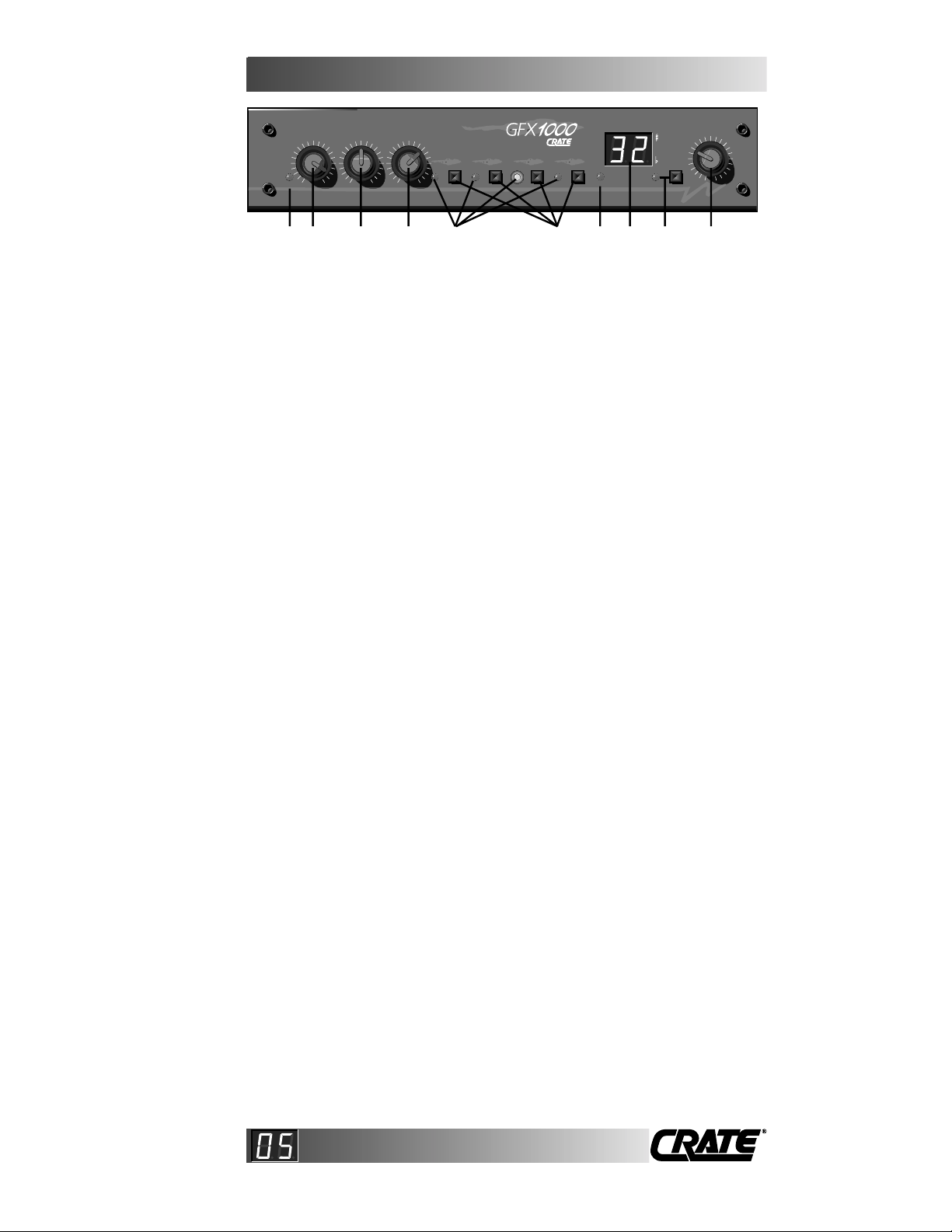
The Front Panel . . . . . . . . . . . . . . . . . . . . . . . . . . . . . . . . . . .5
The Rear Panel . . . . . . . . . . . . . . . . . . . . . . . . . . . . . . . . . . . .6
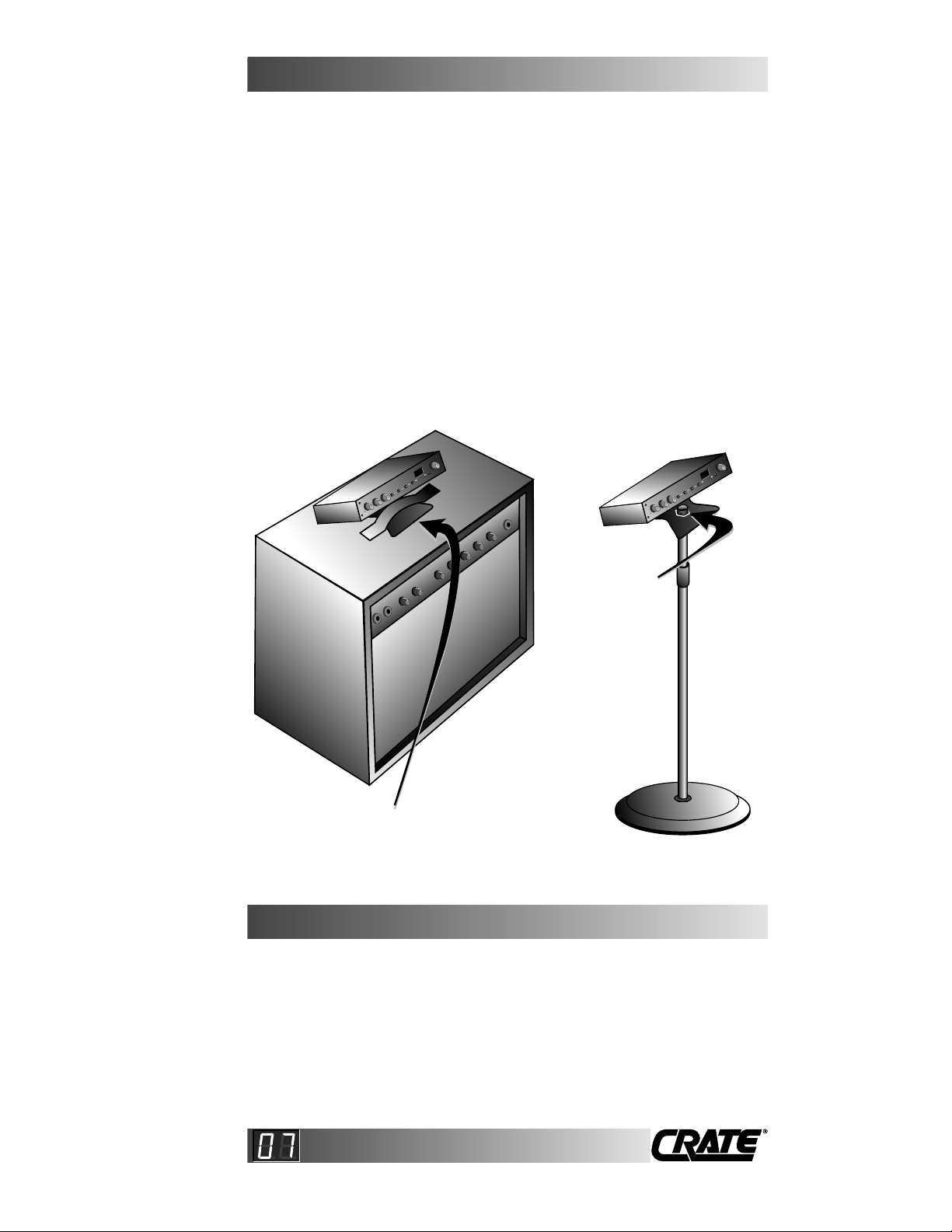
Use of the Mounting Bracket . . . . . . . . . . . . . . . . . . . . . . . . .7
Using a Rack Mount Tray . . . . . . . . . . . . . . . . . . . . . . . . . . .8
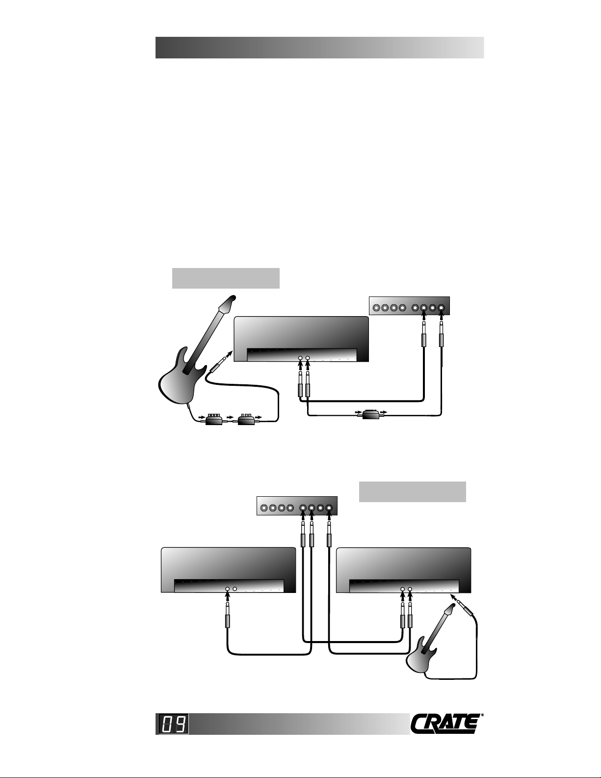
Methods of Connection . . . . . . . . . . . . . . . . . . . . . . . . . .9, 10
Program Groups . . . . . . . . . . . . . . . . . . . . . . . . . . . . . . . . . .11
Program Group Chart - GFX-1000 . . . . . . . . . . . . . . . . . . . .12
Program Group Chart - BFX-1000 . . . . . . . . . . . . . . . . . . . .13
Saving Programs as Presets . . . . . . . . . . . . . . . . . . . . . . . .14
Editing and Saving Programs . . . . . . . . . . . . . . . . . . . . . . .14
Editable Parameters - GFX-1000 . . . . . . . . . . . . . . . . . .15, 16
Editable Parameters - BFX-1000 . . . . . . . . . . . . . . . . . .17, 18
Restoring the Default Programs . . . . . . . . . . . . . . . . . . . . .19
Resetting the Unit . . . . . . . . . . . . . . . . . . . . . . . . . . . . . . . .19
Test Tones . . . . . . . . . . . . . . . . . . . . . . . . . . . . . . . . . . . . . .20
Using the Tuner . . . . . . . . . . . . . . . . . . . . . . . . . . . . . . . . . .21
Using the Metronome . . . . . . . . . . . . . . . . . . . . . . . . . . . . .22
Discrete Stereo Effects . . . . . . . . . . . . . . . . . . . . . . . . .23, 24
Use with Footswitches . . . . . . . . . . . . . . . . . . . . . . . . . .25, 26
Footswitch Amp Control / “Assigning” Effects . . . . . . .27-34
Effect Parameter Technical Aspects - GFX-1000 . . . . . .35, 36
Effect Parameter Technical Aspects - BFX-1000 . . . . . .37, 38
Troubleshooting . . . . . . . . . . . . . . . . . . . . . . . . . . . . . . . . . .39
Block Diagrams . . . . . . . . . . . . . . . . . . . . . . . . . . . . . . . . . .40
Notes . . . . . . . . . . . . . . . . . . . . . . . . . . . . . . . . . . . . . . . . . .41
Specs . . . . . . . . . . . . . . . . . . . . . . . . . . . . . . . . . . . . . . . . . .42
TT
TTaa
aabb
bbll
llee
ee
oo
ooff
ff
CC
CCoo
oonn
nntt
ttee
eenn
nntt
ttss
ss
√
CAUTION
RISK OF ELECTRIC SHOCK
DO NOT OPEN
CAUTION: TO REDUCE THE RISK OF ELECTRIC SHOCK,
DO NOT REMOVE COVER.
NO USER-SERVICEABLE PARTS INSIDE.
REFER SERVICING TO QUALIFIED SERVICE PERSON-
NEL.
ATTENTION
RISQUE D'ELECTROCUTION
NE PAS OUVRIR
ATTENTION: POUR REDUIRE
D'ELECTROCUTION NE PAS
ENLEVER LE COUVERCLE. AUCUNE
PIECE INTERNE N'EST REPRABLE
PAR L'UTILISATEUR. POUR TOUTE
REPARATION, S'ADRESSER A UN
TECHNICIEN QUALIFIE.
VORSICHT
ELEKTRISCHE SCHLAGGEFAHR
NICHT OFFENEN
VORSICHT: ZUR MINIMIERUNG ELEK-
TRISCHER SCHLAGGEFAHR NICHT
DEN DECKEL ABENHMEN. INTERNE
TEILE KONNEN NICHT VOM
BENUTZER GEWARTET WERDEN.
DIE WARTUNG IS QUALIFIZIERTEM
WARTUNGSPERSONAL ZU UBER-
LASSEN.
THIS EQUIPMENT HAS BEEN DESIGNED AND ENGINEERED TO PROVIDE SAFE AND
RELIABLE OPERATION. IN ORDER TO PROLONG THE LIFE OF THE UNIT AND PRE-
VENT ACCIDENTAL DAMAGES OR INJURY, PLEASE FOLLOW THESE PRECAUTION-
ARY GUIDELINES:
CAUTION: TO REDUCE THE RISK OF ELECTRIC SHOCK, DO NOT OPEN CHASSIS.
WARNING: TO REDUCE THE RISK OF FIRE OR ELECTRIC SHOCK, DO NOT EXPOSE
THIS EQUIPMENT TO RAIN OR MOISTURE.
CAUTION: NO USER-SERVICEABLE PARTS INSIDE. REFER SERVICING TO QUALIFIED
SERVICE PERSONNEL.
"IT IS NECESSARY FOR THE USER TO REFER TO THE
INSTRUCTION MANUAL"
"REFERREZ-VOUS AU MANUAL D'UTILISATION"
"UNBEDINGT IN DER BEDIENUNGSANLEITUNG
NACHSCHLAGEN"
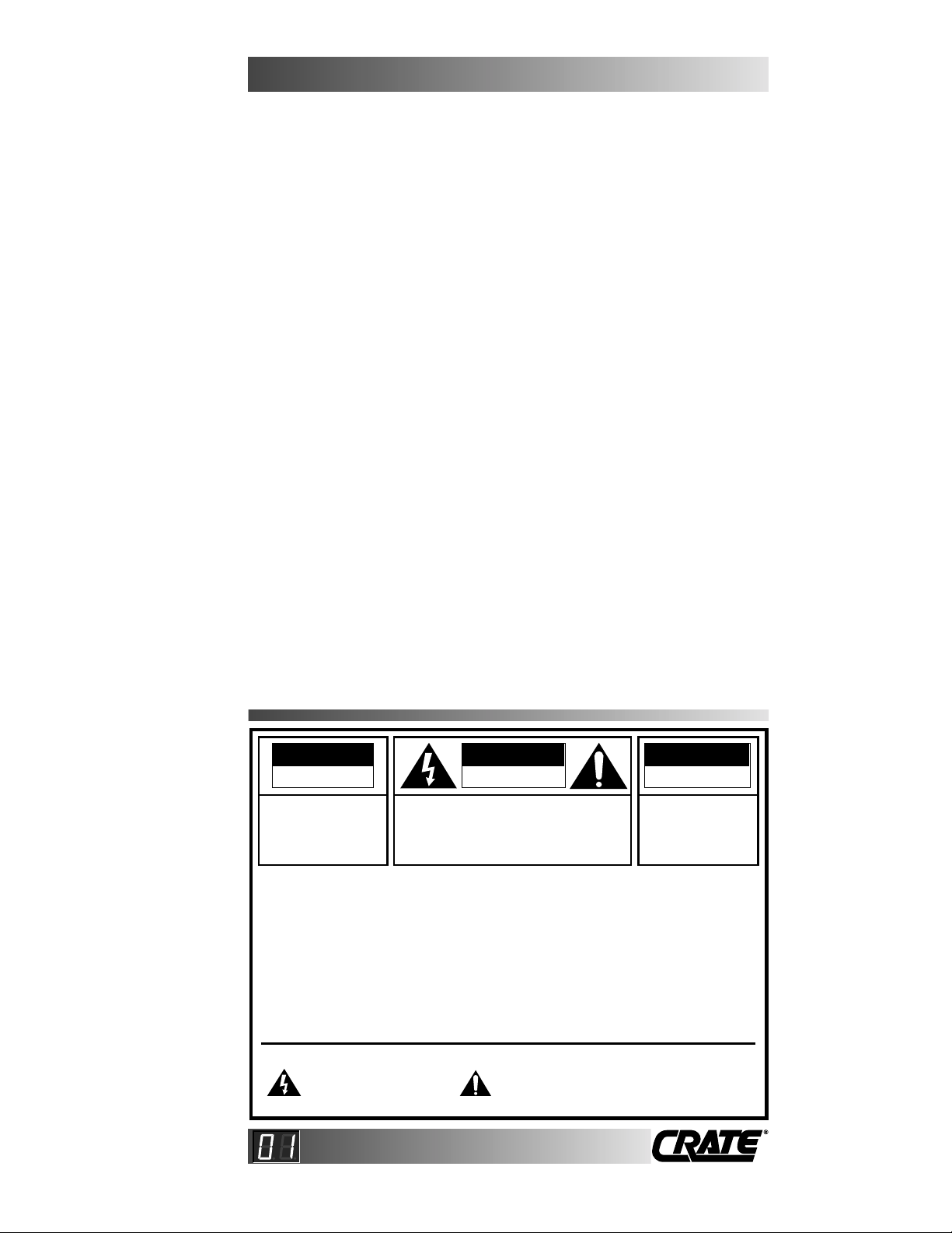
EXPLANATION OF GRAPHICAL SYMBOLS:
"DANGEROUS VOLTAGE"
"DANGER HAUTE TENSION"
"GEFAHLICHE SPANNUNG"
==

You are now the proud owner of one of the most versatile and
innovative effects processors available, the Crate GFX/BFX-1000
Digital Effects Processor. In order to fully understand the capabili-
ties of this unit, you should take the time to read the information in this
manual. In order to appreciate the simplicity of this unit, you could
jump ahead to the “QUICK START GUIDE” on page 3.
And THANK YOU for choosing .
CC
CCoo
oonn
nngg
ggrr
rraa
aatt
ttuu
uull
llaa
aatt
ttii
iioo
oonn
nnss
ss!!
!!
•True DSP (Digital Signal Processing) 16-bit power using Crate’s
exclusive Adaptive Algorithm Processing (AAP)
•100 specially-chosen program settings, including reverbs, delays,
multi-tap delays, echoes, chorus, flange, multi-effects, metronome,
test tones and tuner
•Easy editing of program settings; all user configurations automati-
cally stored (no batteries required for storage)
•Stereo in and out jacks
•Stereo insert jacks with choice of polarity for easy hookup to ampli-
fiers with an “Insert / Effects Loop” jack
•Many reverb algorithms from which to choose
•Many “special effects” settings such as infinite delays and pitch
detuning
•Digital display for program, editing and tuning
•Stereo headphone output jack
•Amp handle / mic stand mounting bracket included
•One rack-space high, 1/2 rack-space wide - fit one or two into a
standard rack mount tray (optional)
•Crate’s FIVE-YEAR WARRANTY (U.S. only)
•Musician Made in the U.S.A.
√: QUICK STARTGUIDE ON NEXT PAGE!!
FF
FFee
eeaa
aatt
ttuu
uurr
rree
eess
ss
GG
GGFF
FFXX
XX//
//BB
BBFF
FFXX
XX--
--11
1100
0000
0000
00
AA
AAcc
cccc
ccee
eess
ssss
ssoo
oorr
rrii
iiee
eess
ss
Packed along with your new GFX/BFX processor are the following:
(1) power pack (1) mounting bracket
(2) mounting bracket screws (2) adhesive foam strips
(1) owners manual (1) warranty packet (U.S. only)
Retain the carton in case of future need, and be sure to activate your
FIVE YEAR WARRANTY (U.S. only) by filling out and mailing in your
registration card.

This “Quick-Start Guide” is intended to get you acquainted with
the basic connection and operation of the processor. Three basic
methods of connection are shown here: using an effects loop,
using an insert jack, and the direct-into-the-amp method.
This section doesn’t cover advanced usage, such as effects
parameter modifications and saving of new programs, or explain
how to use the unit with footswitches, or get you into the
metronome function. It will, however, get you started quickly on
your GFX/BFX experience.
1) Turn your amplifier OFF before connecting the processor.
2) Plug the small connector of the power supply into the power jack
on the back of the unit.
3) Plug the power supply into a wall outlet (power strip, extension
cord, etc.) The unit automatically turns itself on.
4) Connect your instrument and the processor to your amplifier in
one of the following manners: (See to the drawings on the facing
page.)
A: USING AN EFFECTS LOOP: SEND jack of the effects loop to the
R/MONO IN jack of the processor. R/MONO OUT of the processor
to the RETURN jack of the effects loop. Connect your instrument
to your amp as usual.
B: USING AN INSERT JACK: INSERT jack of the amp to the INSERT
(STANDARD) jackof theprocessor.Useastereocable.Ifyourinsertjack
is inverting, plug into the INSERT (INVERTED) jack of the processor.
Connect your instrument to your amp as usual.
C: DIRECT-INTO-THE-AMP: (Not the preferred method.) Output of your
instrument to the R/MONO IN jack of the processor. R/MONO OUT
of the processor to the INPUT jack of your amp.
NOTE: Any other effects and signal processors should be con-
nected between your instrument and the processor; the processor
should be the last link of the chain going into your amplifier.
5) Turn on your amp and set its volume to your normal playing level.
6) Turn your instrument volume up and play as hard as you intend to.
7) Adjust the INPUT control on the processor until its CLIP LED
flashes, then reduce the Input slightly. (The aim is to have the level
as high as it can be without the CLIP LED flashing at all during
play.)
8) Start with the MIX and OUTPUT controls on the processor at the
half-way points, then adjust to taste.
You can get a good feel for the effects available just by running
through the presets, and by turning the PROGRAM dial. A listing
of effects is printed on pages 12 (GFX) and 13 (BFX). Enjoy your
new effects processor, of course; but, please, read this manual!
GG
GGFF
FFXX
XX//
//BB
BBFF
FFXX
XX--
--11
1100
0000
0000
00
QQ
QQuu
uuii
iicc
cckk
kk
SS
SStt
ttaa
aarr
rrtt
tt
GG
GGuu
uuii
iidd
ddee
ee

GG
GGFF
FFXX
XX//
//BB
BBFF
FFXX
XX--
--11
1100
0000
0000
00
QQ
QQuu
uuii
iicc
cckk
kk
SS
SStt
ttaa
aarr
rrtt
tt
GG
GGuu
uuii
iidd
ddee
ee
EFFECTS LOOP
EFFECTS LOOP
AMP
A USING AN EFFECTS LOOP:
RETURN SEND
TO INPUT
JACK
INPUT
JACK
OUT IN
OUT IN
PROCESSOR
PROCESSOR
R/MONO R/MONO
OUT IN
OUT IN
R/MONO R/MONO
AMP
B USING AN INSERT JACK:
INSERT
(STANDARD)
PROCESSOR
INSERT JACK
(ALSO CALLED
SINGLE-JACK
EFFECTS LOOP)
(MOST INSERT JACKS
ARE NON-INVERTING; IF
THIS DOESN'T WORK
WITH YOUR AMP,
YOURS MAY BE
INVERTING; CONNECT
TO THE "INVERTED"
JACK OF THE
PROCESSOR)
AMP
C DIRECT INTO THE AMP:
INPUT
JACK
OUT IN
OUT IN
The cable from the amp to the
processor is a stereo 1/4" signal
cable. All others are mono cables.
All cables shown here
are "mono" 1/4" signal
cables
All cables shown here
are "mono" 1/4" signal
cables
Note that methods “A”
and “B” are preferred
over method “C.”

INPUT MIX OUTPUT
CLIP LEVEL STYLE
1 2 3
EDIT
ON
4
PROGRAM
1 CLIP LED: This LED will light up when the input signal level is set
too high, indicating clipping of the input signal. For proper opera-
tion this LED should NOT light up when using the processor. (See
#2.)
2 INPUT: This control sets the level of the signal going into the
processor. For proper operation, turn this control up until the CLIP
LED (#1) starts to flash when playing at your loudest levels, then
back it down a little until the LED stops flashing. This insures the
best signal-to-noise ratio without distortion.
3 MIX: This control adjusts the mixture of the original signal and the
applied effect at the processor’s outputs. The further to the right
you turn this control, the more effect is applied.
4 OUTPUT: This control adjusts the output level of the signal from
the processor. Typically this control is set for “unity gain” - that is,
the output level is the same as the input signal level. You may, of
course, use the settings that best suit your playing style.
5 PRESET LEDS: The primary function of these LEDs is to show
which preset you have selected. The #4 LED also serves as the
LEVEL indicator when in the EDIT mode. All four LEDs also serve
as 100’s-place indicators for the digital display when using the test
tones and metronome. (See pages 20, 22.)
6 PRESET SWITCHES: The primary function of these momentary
push button switches is to select a preset effect. The #4 selector
also toggles between LEVEL and STYLE when in the EDIT mode.
(See page 14.)
7 STYLE LED: This LED is only used in the EDIT mode, showing
that the changes made to the program will effect a certain para-
meter, rather than the output level for that effect. (See page 14.)
8 DIGITAL DISPLAY: This multi-purpose two-digit display shows
various information, depending on the operating mode:
Basic Operation: Program setting chosen
Editing Parameters: Level and style of parameter being changed
Test Tones: Frequency (in hertz) of tone selected
Tuner: String being tuned and if sharp, flat, or right on
Metronome: Output level / tempo
9 EDIT LED & SWITCH: These are used in the EDIT mode, allow-
ing you to change the levels and styles of the effects. (See page
14.)
10 PROGRAM: The primary function of this control is to select an
effect. This control also serves as the parameter modifier control
when in the EDIT mode. (See page 14.)
12 3 4 5 6 7 8 9 10
GG
GGFF
FFXX
XX//
//BB
BBFF
FFXX
XX--
--11
1100
0000
0000
00
TT
TThh
hhee
ee
FF
FFrr
rroo
oonn
nntt
tt
PP
PPaa
aann
nnee
eell
ll

9-10VAC / 50-60Hz
1000-2000mA
Made in the USA
by SLM Electronics
1400 Ferguson Ave.
St. Louis, MO 63133 IN 1 IN 2FOOTSWITCH
OUT 1 OUT 2 LEFT R / MONO
STEREO OUT
(PHONES / HI-Z) INSERT(STANDARD)
OUT
RETURN
SEND
LEFT R / MONO
STEREO IN
INSERT(INVERTED)
IN
SEND
RETURN
0000001GFX-1000
CLASS
2
11 12 13 14 15 16
11 POWER JACK: Plug the small connector from the AC power pack
into this jack. Plug the power pack into a suitable source of the
proper AC voltage, as indicated on the power pack.
NOTE: The processor is always on when the power pack is
plugged in and connected to the unit. It is advised that you
unplug the power pack from the AC source when not using
the processor for extended time periods.
12 FOOTSWITCH JACKS: Up to 16 presets can be accessed and
assigned to your amplifier by proper use of footswitches. See
pages 25 through 34 for complete details and instructions.
13 LEFT OUT / STEREO OUT (PHONES / HI-Z): This jack serves
two purposes: (1) When using the processor in a stereo mode,
connect a mono signal cable from this jack to your left-channel
amp. (2) When using headphones with the processor, plug them
into this jack. When the processor is connected to an Insert/Effects
Loop jack (single jack, not loop), this jack is not used. (See pages
9, 10.)
14 R/MONO OUT / INSERT (STANDARD): This jack serves two pur-
poses: (1) When using the processor in a stereo mode, connect a
mono signal cable from this jack to your right-channel amp. (2)
When using an amp’s INSERT jack, connect a stereo signal cable
from this jack to the Insert jack on the amp - if it’s “non-inverting”
(see the drawing beneath #16). If the Insert jack is inverting, use
#16, not this jack. (See page 10.)
15 LEFT IN / STEREO IN: This jack serves two purposes: (1) When
using a stereo preamp or guitar with two mono outputs, connect
a mono signal cable from the left channel output to this jack. (2)
When using a stereo preamp or guitar with a single stereo out-
put, connect a stereo signal cable from its output to this jack. (See
pages 9, 10.)
16 R/MONO IN / INSERT (INVERTED): This jack serves two purpos-
es: (1) When using the processor in a stereo mode, connect a
mono signal cable from this jack to your right-channel amp. (2)
When using an amp’s Insert jack, connect a stereo signal cable
from this jack to the Insert jack on the amp - if it’s “inverting” (see
the drawing below). If the Insert jack is non-inverting, use #14, not
this jack. (See page 10.)
GG
GGFF
FFXX
XX//
//BB
BBFF
FFXX
XX--
--11
1100
0000
0000
00
TT
TThh
hhee
ee
RR
RRee
eeaa
aarr
rr
PP
PPaa
aann
nnee
eell
ll
NON-INVERTING (STANDARD):
TIP = RETURN RING = SEND
SLEEVE = GROUND
INVERTING (NOT AS COMMON):
TIP = SEND RING = RETURN
SLEEVE = GROUND

The processor can be mounted on top of your amplifier (or other
flat surface) or on a mic stand by use of its specially-designed mount-
ing bracket.
Screw the bracket onto the bottom of the processor, using only
the 6-32 x 3/16” screws provided. To prevent possible damage to
the unit, DO NOT use longer screws!
Slip the bracket under your amp’s handle for amp-top mounting.
Pressing the handle down onto the bracket (strap-style handles) helps
hold the unit in place better.
For mic stand mounting, stick the top threaded part of the stand
up through the hole in the bottom part of the bracket, then screw a
retaining nut (available from your music supply store) onto the stand
and tighten it against the bracket.
GG
GGFF
FFXX
XX//
//BB
BBFF
FFXX
XX--
--11
1100
0000
0000
00
UU
UUss
ssee
ee
oo
ooff
ff
tt
tthh
hhee
ee
MM
MMoo
oouu
uunn
nntt
ttii
iinn
nngg
gg
BB
BBrr
rraa
aacc
cckk
kkee
eett
tt
The peel-and-stick foam strips that come with the processor may
be applied to the bottom of the unit, to help keep it from slipping off of
whatever you set it on. When using the mounting bracket on top of an
amplifier, you can adhere the foam strips to the underside of the
bracket, to help it keep its grip on the amp.
TT
TThh
hhee
ee
AA
AAdd
ddhh
hhee
eess
ssii
iivv
vvee
ee--
--BB
BBaa
aacc
cckk
kkee
eedd
dd
FF
FFoo
ooaa
aamm
mm
SS
SStt
ttrr
rrii
iipp
ppss
ss
SLIP BRACKET UNDER
HANDLE (STICK FOAM
STRIPS TO BRACKET
BOTTOM –OPTIONAL)
SECURE
WITH
RETAINING
NUT
AMP TOP
MOUNTING: MIC STAND
MOUNTING:

GG
GGFF
FFXX
XX//
//BB
BBFF
FFXX
XX--
--11
1100
0000
0000
00
UU
UUss
ssii
iinn
nngg
gg
aa
aa
RR
RRaa
aacc
cckk
kk
MM
MMoo
oouu
uunn
nntt
tt
TT
TTrr
rraa
aayy
yy
The processor can be rack mounted using the universal rack
mount tray available through your Crate dealer. Each units is one-half
rack space in width so two fit side by side.
The two threaded holes in the bottom of the processor line up
with two of the mounting holes in the rack mount tray. Use the two 6-
32 x 3/16” screws provided to secure the unit to the tray. DO NOT use
longer screws!
TWO PROCESSORS (ONE
BFX AND ONE GFX, OR
TWO OF EACH) SIDE BY
SIDE IN RACK TRAY:
ONE PROCESSOR IN
RACK TRAY WITH 1/2-
RACK "BLANK":
SECURE WITH (2)
6-32 X 3/16"
SCREWS SUPPLIED

GG
GGFF
FFXX
XX//
//BB
BBFF
FFXX
XX--
--11
1100
0000
0000
00
MM
MMee
eett
tthh
hhoo
oodd
ddss
ss
oo
ooff
ff
CC
CCoo
oonn
nnnn
nnee
eecc
cctt
ttii
iioo
oonn
nn
There are a number of different ways to hook up the processor.
The recommended method of connection is through the effects loop /
insert jack of your amplifier. Also acceptable, but not preferred, is the
plug-it-right-into-the-input-jack method. In any case, the processor
should be the LAST component before the connection is made to the
amplifier.
Some of the possible connections are shown below and on the
facing page. When using the INSERT jack of the processor, try to find
out if your amplifier’s INSERT/EFFECTS LOOP jack is “standard”
(non-inverted) or “inverted”. If in doubt, try connecting the cable to the
processor’s INSERT(STANDARD) jack first. If this doesn’t work, use the
INSERT(INVERTED) jack.
We’ve thrown in a few tips on placement of other effects pedals
in the signal path. These aren’t absolutes, just things we’ve found
from experience.
CONNECTED THROUGH THE EFFECTS LOOP OF ONE AMP:
TO
INPUT
JACK EFFECTS LOOP
EFFECTS LOOP
AMP
RETURN SEND
OUT IN
OUT IN
PROCESSOR
PROCESSOR
R/MONO R/MONO
EQ pedals are okay for the
effects loop
All cables shown here are
"mono" 1/4" signal cables
Compressors, noise gates,
T-Wahs, distortion pedals
should run right into the amp
Pedals follow same suggestions
as above
IN OUT IN OUT IN OUT
CONNECTED IN STEREO TO TWO AMPS:
TO
INPUT
JACK
EFFECTS LOOP
EFFECTS LOOP
LEFT AMP
RETURN SEND
EFFECTS LOOP
EFFECTS LOOP
RIGHT AMP
RETURN SEND
All cables shown here are
"mono" 1/4" signal cables
OUT IN
OUT IN
R/MONOL R

GG
GGFF
FFXX
XX//
//BB
BBFF
FFXX
XX--
--11
1100
0000
0000
00
MM
MMee
eett
tthh
hhoo
oodd
ddss
ss
oo
ooff
ff
CC
CCoo
oonn
nnnn
nnee
eecc
cctt
ttii
iioo
oonn
nn
If you skipped over the Quick Start Guide on page 3, you might
want to go back and read the steps for connecting and beginning to
use your new processor. It is recommended that you get familiar with
the unit before progressing to editing and saving programs, using the
metronome and tuner, and using the footswitch controls.
INPUT
JACK
OUT IN
OUT IN
R/MONO R/MONO
AMP
CONNECTED THROUGH AN INSERT JACK:
INSERT
(STANDARD)
PROCESSOR
PROCESSOR
INSERT JACK
(OR SINGLE-JACK
EFFECTS LOOP)
(MOST INSERT JACKS
ARE NON-INVERTING;
IF THIS DOESN'T WORK
WITH YOUR AMP,
YOURS MAY BE
INVERTING; CONNECT
TO THE "INVERTED"
JACK OF THE
PROCESSOR)
DIRECT INTO AN AMPLIFIER:
OUT IN
OUT IN
R/MONOPHONES / HI-Z
USING HIGH-IMPEDANCE, WALKMAN TYPE HEADPHONES:
AMP
INPUT
JACK
Pedals run right into the amp
IN OUT IN OUT IN OUT
Pedals connected before the processor
IN OUT IN OUT IN OUT
All cables shown here are
"mono" 1/4" signal cables
The cable from the amp to the processor is a stereo
1/4" signal cable (ring-tip-sleeve, shown to the right).
All others are mono cables.
PROCESSOR

GG
GGFF
FFXX
XX//
//BB
BBFF
FFXX
XX--
--11
1100
0000
0000
00
PP
PPrr
rroo
oogg
ggrr
rraa
aamm
mm
GG
GGrr
rroo
oouu
uupp
ppss
ss
The processors have 100 different effects programs available.
These can be divided up into 7 groups, as follows:
multi-effects: 00-29 (both)
special effects: 30-39 (both)
delays: 40-59 (both)
choruses: 60-69 (GFX) 70-84 (BFX)
reverbs: 70-84 (GFX) 60-69 (BFX)
discrete stereo effects: 85-96 (both)
utility programs: 97-99 (both)
(test tones, tuner, metronome)
The charts on the following pages show the program number, the
name of the effect, whether it uses chorus, flanging, delay and/or
reverb, and other useful information for each of the processors.
Some things to know about the digital display:
When you power up the processor, it runs itself through a quick
self-test, then goes to whatever preset you last saved. When the unit
is turned on for the very first time (before any presets have been
changed), or is “reset” (see page 19), none of the presets will be lit
and the display will read “00.”
When using the tuner, the display characters for the notes being
tuned will read out in upper or lower case, depending on the note. The
notes will look like this (see also page 21):
EFgAbCd
IMPORTANT NOTE: In the unlikely event the processor locks up, the
display will show the letter “F.” (This is not to be confused with the pos-
sibility of the “F” appearing when using the tuner.) If this happens, try
resetting the unit (see page 19). If the display still shows an “F” after
resetting, pull the plug and call for service!

GG
GGFF
FFXX
XX//
//BB
BBFF
FFXX
XX--
--11
1100
0000
0000
00
PP
PPrr
rroo
oogg
ggrr
rraa
aamm
mm
GG
GGrr
rroo
oouu
uupp
ppss
ss
CC
CChh
hhaa
aarr
rrtt
tt
--
--
GG
GGFF
FFXX
XX--
--11
1100
0000
0000
00
No. Effect Cho Dly Rvb
75 bright rvb 6 •
76 warm rvb 1 •
77 warm rvb 2 •
78 warm rvb 3 •
79 warm rvb 4 •
80 warm rvb 5 •
81 warm rvb 6 •
82 dark rvb 1 •
83 dark rvb 2 •
84 dark rvb 3 •
85 discrete in/out right left
86 discrete in/out left right
87 discrete in/out right left
88 discrete in/out left left right
89 discrete in/out right left left
90 discrete in/out right left right
91 discrete in/mix out right left
92 discrete in/mix out left right
93 discrete in/mix out right left
94 discrete in/mix out left left right
95 discrete in/mix out right left left
96 discrete in/mix out right left right
97 test tones 35 - 499 Hz
98 tuner E F g A b C d
99 metronome 48 - 208 BPM
No. Effect Cho Dly Rvb
50 echo 5 •
51 ping-pong 1 •
52 ping-pong 2 •
53 ping-pong 3 •
54 ping-pong 4 •
55 off beat 1 •
56 off beat 2 •
57 off beat 3 •
58 off beat 4 •
59 off beat 5 •
60 chorus 1 •
61 chorus 2 •
62 chorus 3 •
63 chorus 4 •
64 chorus 5 •
65 chorus 6 •
66 chorus 7 •
67 chorus 8 •
68 chorus 9 •
69 chorus 10 •
70 bright rvb 1 •
71 bright rvb 2 •
72 bright rvb 3 •
73 bright rvb 4 •
74 bright rvb 5 •
No. Effect Cho/Flng Dly Rvb
25 dly+cho 1 chorus •
26 dly+cho 2 chorus •
27 dly+cho 3 chorus •
28 dly+cho 4 chorus •
29 dly+cho 5 chorus •
30 stupor chorus ••
31 vertigo chorus ••
32 varitap ••
33 infinity chorus ••
34 entropy ••
35 space flange flange ••
36 bumble bee chorus ••
37 the shadow chorus ••
38 huge room chorus ••
39 B movie chorus ••
40 dly 0-99ms •
41 dly 100-199ms •
42 dly 200-299ms •
43 dly 300-399ms •
44 dly 400-499ms •
45 dly 500-599ms •
46 echo 1 •
47 echo 2 •
48 echo 3 •
49 echo 4 •
No. Effect Cho/Flng Dly Rvb
00 super guitar 1 chorus ••
01 super guitar 2 chorus ••
02 concert chorus ••
03 overkill chorus ••
04 duet chorus ••
05 subtle chorus ••
06 fat boy chorus ••
07 tremchorus chorus ••
08 thick chorus ••
09 chorus room chorus ••
10 verb 1 chorus ••
11 verb 2 chorus ••
12 flng+rvb flange •
13 flng+dly flange •
14 flng+dly+rvb flange ••
15 rvb+dly 1 ••
16 rvb+dly 2 ••
17 rvb+dly 3 ••
18 rvb+dly 4 ••
19 rvb+dly 5 ••
20 rvb+cho 1 chorus •
21 rvb+cho 2 chorus •
22 rvb+cho 3 chorus •
23 rvb+cho 4 chorus •
24 rvb+cho 5 chorus •
This chart is for the GFX-1000 processor. The chart for the BFX-1000 is
on the following page.

GG
GGFF
FFXX
XX//
//BB
BBFF
FFXX
XX--
--11
1100
0000
0000
00
PP
PPrr
rroo
oogg
ggrr
rraa
aamm
mm
GG
GGrr
rroo
oouu
uupp
pp
CC
CChh
hhaa
aarr
rrtt
tt
--
--BB
BBFF
FFXX
XX--
--11
1100
0000
0000
00
No. Effect Cho Dly Rvb
75 chorus 6 •
76 chorus 7 •
77 chorus 8 •
78 chorus 9 •
79 chorus 10 •
80 chorus 11 •
81 chorus 12 •
82 chorus 13 •
83 chorus 14 •
84 chorus 15 •
85 discrete in/out right left
86 discrete in/out left right
87 discrete in/out right left
88 discrete in/out left left right
89 discrete in/out right left left
90 discrete in/out right left right
91 discrete in/mix out right left
92 discrete in/mix out left right
93 discrete in/mix out right left
94 discrete in/mix out left left right
95 discrete in/mix out right left left
96 discrete in/mix out right left right
97 test tones 35 - 499 Hz
98 tuner E F g A b C d
99 metronome 48 - 208 BPM
No. Effect Cho Dly Rvb
50 echo 5 •
51 ping-pong 1 •
52 ping-pong 2 •
53 ping-pong 3 •
54 ping-pong 4 •
55 off beat 1 •
56 off beat 2 •
57 off beat 3 •
58 off beat 4 •
59 off beat 5 •
60 bright rvb 1 •
61 bright rvb 2 •
62 bright rvb 3 •
63 bright rvb 4 •
64 warm rvb 1 •
65 warm rvb 2 •
66 warm rvb 3 •
67 warm rvb 4 •
68 dark rvb 1 •
69 dark rvb 2 •
70 chorus 1 •
71 chorus 2 •
72 chorus 3 •
73 chorus 4 •
74 chorus 5 •
No. Effect Cho/Flng Dly Rvb
25 dly+cho 1 chorus •
26 dly+cho 2 chorus •
27 dly+cho 3 chorus •
28 dly+cho 4 chorus •
29 dly+cho 5 chorus •
30 stupor chorus ••
31 vertigo chorus ••
32 varitap ••
33 infinity chorus ••
34 entropy ••
35 space flange flange ••
36 bumble bee chorus ••
37 the shadow chorus ••
38 huge room chorus ••
39 B movie chorus ••
40 dly 0-99ms •
41 dly 100-199ms •
42 dly 200-299ms •
43 dly 300-399ms •
44 dly 400-499ms •
45 dly 500-599ms •
46 echo 1 •
47 echo 2 •
48 echo 3 •
49 echo 4 •
No. Effect Cho/Flng Dly Rvb
00 super bass 1 chorus ••
01 super bass 2 chorus ••
02 concert chorus ••
03 overkill chorus ••
04 duet chorus ••
05 subtle chorus ••
06 fat boy chorus ••
07 tremchorus chorus ••
08 thick chorus ••
09 chorus room chorus ••
10 verb 1 chorus ••
11 verb 2 chorus ••
12 flng+rvb flange •
13 flng+dly flange •
14 flng+dly+rvb flange ••
15 rvb+dly 1 ••
16 rvb+dly 2 ••
17 rvb+dly 3 ••
18 rvb+dly 4 ••
19 rvb+dly 5 ••
20 rvb+cho 1 chorus •
21 rvb+cho 2 chorus •
22 rvb+cho 3 chorus •
23 rvb+cho 4 chorus •
24 rvb+cho 5 chorus •
This chart is for the BFX-1000 processor. The chart for the GFX-1000 is
on the preceding page.

The effects processor comes shipped from the factory with the
presets set at program 01 for preset #1, 02 for #2, 04 for #3 and 08
for #4. (These are also the settings the unit reverts to when it is reset
- see page 19.)
Any of the 100 programs may be stored as any of the presets (up
to 16 with the use of footswitches - see pages 25 - 34). To assign an
effect as a preset, turn the processor ON and follow this example:
Example 1: Assigning effect #32 as preset #1:
1. Press preset button #1. The LED next to the button will light up.
2. Turn the PROGRAM knob until the display window shows “32.”
The #1 preset is now temporarily set as “32” - it will remain that
way until the unit is turned off. To lock the preset in memory (so it will
be there when the unit is turned on again later):
3. Press the EDIT button two times. The EDITLED will light up (along
with the STYLE or LEVEL LED) at the first press, then go out at
the second press.
The #1 preset is now “permanently” set as “32” - it will stay there
until you store another program in preset #1.
Any of the programs (except the tuner) may be custom-tailored,
then saved to memory if desired. For each program, two characteris-
tics may be modified: the level and the style. Style refers to a specif-
ic parameter (such as decay time for reverbs), determined by the type
of effect. To edit and save a preset, turn the processor ON and follow
this example:
Example 2: Editing effect #21 and saving it:
1. Press preset button #1. The LED next to the button will light up.
2. Turn the PROGRAM knob until the display window shows “21.”
3. Press the EDIT button. The EDIT LED will light up, along with
either the LEVEL or STYLE LED.
4. Press the #4 button to switch between LEVEL and STYLE (follow
the LEDs). To change how much of the effect is added to the sig-
nal, stop when the LEVEL LED is lit and turn the PROGRAM knob
to the desired setting (00 being “off” and 99 being maximum). To
change the effects parameter (in this case, the tap offset - see the
chart on the next page), press the #4 button until the STYLE LED
is lit, then turn the PROGRAM knob to the desired setting. You can
listen to the way the changes affect the sound by playing while
making the changes.
5. Press the EDIT button again. The EDIT LED will go out - the
changes have now been made and saved.
The next 4 pages show the program number, the name of the
effect, the parameter which can be changed and its upper and lower
limits for the GFX (pages 15 and 16) and BFX (pages 17 and 18).
EE
EEdd
ddii
iitt
ttii
iinn
nngg
gg
aa
aann
nndd
dd
SS
SSaa
aavv
vvii
iinn
nngg
gg
PP
PPrr
rroo
oogg
ggrr
rraa
aamm
mmss
ss
GG
GGFF
FFXX
XX//
//BB
BBFF
FFXX
XX--
--11
1100
0000
0000
00
SS
SSaa
aavv
vvii
iinn
nngg
gg
PP
PPrr
rroo
oogg
ggrr
rraa
aamm
mmss
ss
aa
aass
ss
PP
PPrr
rree
eess
ssee
eett
ttss
ss

This chart shows the program number, the name of the effect,
the parameter which can be changed and its upper and lower limits.
GG
GGFF
FFXX
XX//
//BB
BBFF
FFXX
XX--
--11
1100
0000
0000
00
EE
EEdd
ddii
iitt
ttaa
aabb
bbll
llee
ee
PP
PPaa
aarr
rraa
aamm
mmee
eett
ttee
eerr
rrss
ss
--
--GG
GGFF
FFXX
XX--
--11
1100
0000
0000
00
Variable Low High
No. Effect Parameter Value Value
00 super guitar 1 delay time 6 ms 600 ms
01 super guitar 2 delay time 6 ms 600 ms
02 concert delay time 6 ms 600 ms
03 overkill delay time 6 ms 600 ms
04 duet delay time 6 ms 600 ms
05 subtle delay time 6 ms 600 ms
06 fat boy delay time 6 ms 600 ms
07 tremchorus delay time 6 ms 600 ms
08 thick delay time 6 ms 600 ms
09 chorus room reverb decay .3 sec 15 sec
10 verb 1 reverb decay .3 sec 15 sec
11 verb 2 reverb decay .3 sec 15 sec
12 flng+rvb delay time 6 ms 600 ms
13 flng+dly delay time 6 ms 600 ms
14 flng+dly+rvb delay time 6 ms 600 ms
15 rvb+dly 1 delay time 6 ms 600 ms
16 rvb+dly 2 delay time 6 ms 600 ms
17 rvb+dly 3 delay time 6 ms 600 ms
18 rvb+dly 4 delay time 6 ms 600 ms
19 rvb+dly 5 delay time 6 ms 600 ms
20 rvb+cho 1 reverb decay .3 sec 15 sec
21 rvb+cho 2 reverb decay .3 sec 15 sec
22 rvb+cho 3 reverb decay .3 sec 15 sec
23 rvb+cho 4 reverb decay .3 sec 15 sec
24 rvb+cho 5 reverb decay .3 sec 15 sec
25 dly+cho 1 delay time 6 ms 600 ms
26 dly+cho 2 delay time 6 ms 600 ms
27 dly+cho 3 delay time 6 ms 600 ms
28 dly+cho 4 delay time 6 ms 600 ms
29 dly+cho 5 delay time 6 ms 600 ms
30 stupor delay time 6 ms 600 ms
31 vertigo delay time 6 ms 600 ms
32 varitap tap offset 0 ms 610 ms
33 infinity delay time 6 ms 600 ms
34 entropy delay time 6 ms 600 ms
35 space flange delay time 6 ms 600 ms
36 bumble bee delay time 6 ms 600 ms
37 the shadow delay time 6 ms 600 ms
38 huge room delay time 6 ms 600 ms
39 B movie delay time 6 ms 600 ms
40 dly 0-99ms delay time 0 ms 99 ms
41 dly 100-199ms delay time 100 ms 199 ms
42 dly 200-299ms delay time 200 ms 299 ms
43 dly 300-399ms delay time 300 ms 399 ms
44 dly 400-499ms delay time 400 ms 499 ms
45 dly 500-599ms delay time 500 ms 599 ms
46 echo 1 delay time 6 ms 600 ms
47 echo 2 delay time 6 ms 600 ms
48 echo 3 delay time 6 ms 600 ms
49 echo 4 delay time 6 ms 600 ms
50 echo 5 delay time 6 ms 600 ms
51 ping-pong 1 delay time 6 ms 600 ms
52 ping-pong 2 delay time 6 ms 600 ms
53 ping-pong 3 delay time 6 ms 600 ms
54 ping-pong 4 delay time 6 ms 600 ms
55 off beat 1 delay time 6 ms 600 ms
56 off beat 2 delay time 6 ms 600 ms
57 off beat 3 delay time 6 ms 600 ms
58 off beat 4 delay time 6 ms 600 ms
59 off beat 5 delay time 6 ms 600 ms

GG
GGFF
FFXX
XX//
//BB
BBFF
FFXX
XX--
--11
1100
0000
0000
00
EE
EEdd
ddii
iitt
ttaa
aabb
bbll
llee
ee
PP
PPaa
aarr
rraa
aamm
mmee
eett
ttee
eerr
rrss
ss
--
--GG
GGFF
FFXX
XX--
--11
1100
0000
0000
00
Variable Low High
No. Effect Parameter Value Value
60 chorus 1 speed 0.1 Hz 6.5 Hz
61 chorus 2 speed 0.1 Hz 6.5 Hz
62 chorus 3 speed 0.1 Hz 6.5 Hz
63 chorus 4 speed 0.1 Hz 5.7 Hz
64 chorus 5 speed 0.1 Hz 5.7 Hz
65 chorus 6 depth 0.10% 5.00%
66 chorus 7 depth 0.10% 2.20%
67 chorus 8 depth 0.10% 1.00%
68 chorus 9 depth 0.10% 0.80%
69 chorus 10 depth 0.10% 0.70%
70 bright rvb 1 reverb decay .3 sec 15 sec
71 bright rvb 2 reverb decay .3 sec 15 sec
72 bright rvb 3 reverb decay .3 sec 15 sec
73 bright rvb 4 reverb decay .3 sec 15 sec
74 bright rvb 5 reverb decay .3 sec 15 sec
75 bright rvb 6 reverb decay .3 sec 15 sec
76 warm rvb 1 reverb decay .3 sec 15 sec
77 warm rvb 2 reverb decay .3 sec 15 sec
78 warm rvb 3 reverb decay .3 sec 15 sec
79 warm rvb 4 reverb decay .3 sec 15 sec
80 warm rvb 5 reverb decay .3 sec 15 sec
81 warm rvb 6 reverb decay .3 sec 15 sec
82 dark rvb 1 reverb decay .3 sec 15 sec
83 dark rvb 2 reverb decay .3 sec 15 sec
84 dark rvb 3 reverb decay .3 sec 15 sec
85 discrete in/out delay time 6 ms 600 ms
86 discrete in/out delay time 6 ms 600 ms
87 discrete in/out reverb decay .3 sec 15 sec
88 discrete in/out delay time 6 ms 600 ms
89 discrete in/out delay time 6 ms 600 ms
90 discrete in/out delay time 6 ms 600 ms
91 discrete in/mix out delay time 6 ms 600 ms
92 discrete in/mix out delay time 6 ms 600 ms
93 discrete in/mix out reverb decay 300 ms 15 sec
94 discrete in/mix out delay time 6 ms 600 ms
95 discrete in/mix out delay time 6 ms 600 ms
96 discrete in/mix out delay time 6 ms 600 ms
97 test tones frequency 35 Hz 499 Hz
98 tuner (none) n/a n/a
99 metronome beats per minute 48 BPM 208 BPM
The GFX unit displays a range of 00 to 99 for each parameter.
Use these formulas to convert display readings to actual parameter
values. Enter all values in milliseconds.
To find an exact delay time:
delay time = low value + display value x high value
100
To find which display value to use for a given delay time:
display value = 100 x (delay time - low value)
high value
To convert display value to reverb decay (in seconds):
reverb decay = 30
101 - display value
To find which display value to use for a given delay time:
display value = 101 - (30/reverb decay)
Typically, delay time is editable for delay effects, reverb decay for
reverb effects, and depth or speed for chorus effects.

This chart shows the program number, the name of the effect,
the parameter which can be changed and its upper and lower limits.
GG
GGFF
FFXX
XX//
//BB
BBFF
FFXX
XX--
--11
1100
0000
0000
00
EE
EEdd
ddii
iitt
ttaa
aabb
bbll
llee
ee
PP
PPaa
aarr
rraa
aamm
mmee
eett
ttee
eerr
rrss
ss
--
--BB
BBFF
FFXX
XX--
--11
1100
0000
0000
00
Variable Low High
No. Effect Parameter Value Value
00 super bass 1 delay time 6 ms 600 ms
01 super bass 2 delay time 6 ms 600 ms
02 concert delay time 6 ms 600 ms
03 overkill delay time 6 ms 600 ms
04 duet delay time 6 ms 600 ms
05 subtle delay time 6 ms 600 ms
06 fat boy delay time 6 ms 600 ms
07 tremchorus delay time 6 ms 600 ms
08 thick delay time 6 ms 600 ms
09 chorus room reverb decay .3 sec 15 sec
10 verb 1 reverb decay .3 sec 15 sec
11 verb 2 reverb decay .3 sec 15 sec
12 flng+rvb delay time 6 ms 600 ms
13 flng+dly delay time 6 ms 600 ms
14 flng+dly+rvb delay time 6 ms 600 ms
15 rvb+dly 1 delay time 6 ms 600 ms
16 rvb+dly 2 delay time 6 ms 600 ms
17 rvb+dly 3 delay time 6 ms 600 ms
18 rvb+dly 4 delay time 6 ms 600 ms
19 rvb+dly 5 delay time 6 ms 600 ms
20 rvb+cho 1 reverb decay .3 sec 15 sec
21 rvb+cho 2 reverb decay .3 sec 15 sec
22 rvb+cho 3 reverb decay .3 sec 15 sec
23 rvb+cho 4 reverb decay .3 sec 15 sec
24 rvb+cho 5 reverb decay .3 sec 15 sec
25 dly+cho 1 delay time 6 ms 600 ms
26 dly+cho 2 delay time 6 ms 600 ms
27 dly+cho 3 delay time 6 ms 600 ms
28 dly+cho 4 delay time 6 ms 600 ms
29 dly+cho 5 delay time 6 ms 600 ms
30 stupor delay time 6 ms 600 ms
31 vertigo delay time 6 ms 600 ms
32 varitap tap offset 0 ms 610 ms
33 infinity delay time 6 ms 600 ms
34 entropy delay time 6 ms 600 ms
35 space flange delay time 6 ms 600 ms
36 bumble bee delay time 6 ms 600 ms
37 the shadow delay time 6 ms 600 ms
38 huge room delay time 6 ms 600 ms
39 B movie delay time 6 ms 600 ms
40 dly 0-99ms delay time 0 ms 99 ms
41 dly 100-199ms delay time 100 ms 199 ms
42 dly 200-299ms delay time 200 ms 299 ms
43 dly 300-399ms delay time 300 ms 399 ms
44 dly 400-499ms delay time 400 ms 499 ms
45 dly 500-599ms delay time 500 ms 599 ms
46 echo 1 delay time 6 ms 600 ms
47 echo 2 delay time 6 ms 600 ms
48 echo 3 delay time 6 ms 600 ms
49 echo 4 delay time 6 ms 600 ms
50 echo 5 delay time 6 ms 600 ms
51 ping-pong 1 delay time 6 ms 600 ms
52 ping-pong 2 delay time 6 ms 600 ms
53 ping-pong 3 delay time 6 ms 600 ms
54 ping-pong 4 delay time 6 ms 600 ms
55 off beat 1 delay time 6 ms 600 ms
56 off beat 2 delay time 6 ms 600 ms
57 off beat 3 delay time 6 ms 600 ms
58 off beat 4 delay time 6 ms 600 ms
59 off beat 5 delay time 6 ms 600 ms

GG
GGFF
FFXX
XX//
//BB
BBFF
FFXX
XX--
--11
1100
0000
0000
00
EE
EEdd
ddii
iitt
ttaa
aabb
bbll
llee
ee
PP
PPaa
aarr
rraa
aamm
mmee
eett
ttee
eerr
rrss
ss
--
--BB
BBFF
FFXX
XX--
--11
1100
0000
0000
00
Variable Low High
No. Effect Parameter Value Value
60 bright rvb 1 reverb decay .3 sec 15 sec
61 bright rvb 2 reverb decay .3 sec 15 sec
62 bright rvb 3 reverb decay .3 sec 15 sec
63 bright rvb 4 reverb decay .3 sec 15 sec
64 warm rvb 1 reverb decay .3 sec 15 sec
65 warm rvb 2 reverb decay .3 sec 15 sec
66 warm rvb 3 reverb decay .3 sec 15 sec
67 warm rvb 4 reverb decay .3 sec 15 sec
68 dark rvb 1 reverb decay .3 sec 15 sec
69 dark rvb 2 reverb decay .3 sec 15 sec
70 chorus 1 speed 0.1 Hz 6.5 Hz
71 chorus 2 speed 0.1 Hz 6.5 Hz
72 chorus 3 speed 0.1 Hz 6.5 Hz
73 chorus 4 speed 0.1 Hz 6.5 Hz
74 chorus 5 speed 0.1 Hz 6.5 Hz
75 chorus 6 speed 0.1 Hz 6.5 Hz
76 chorus 7 speed 0.1 Hz 6.5 Hz
77 chorus 8 speed 0.1 Hz 6.5 Hz
78 chorus 9 depth 0.10% 5.00%
79 chorus 10 depth 0.10% 5.00%
80 chorus 11 depth 0.10% 5.00%
81 chorus 12 depth 0.10% 5.00%
82 chorus 13 depth 0.10% 5.00%
83 chorus 14 depth 0.10% 5.00%
84 chorus 15 depth 0.10% 5.00%
85 discrete in/out delay time 6 ms 600 ms
86 discrete in/out delay time 6 ms 600 ms
87 discrete in/out reverb decay .3 sec 15 sec
88 discrete in/out delay time 6 ms 600 ms
89 discrete in/out delay time 6 ms 600 ms
90 discrete in/out delay time 6 ms 600 ms
91 discrete in/mix out delay time 6 ms 600 ms
92 discrete in/mix out delay time 6 ms 600 ms
93 discrete in/mix out reverb decay 300 ms 15 sec
94 discrete in/mix out delay time 6 ms 600 ms
95 discrete in/mix out delay time 6 ms 600 ms
96 discrete in/mix out delay time 6 ms 600 ms
97 test tones frequency 35 Hz 499 Hz
98 tuner (none) n/a n/a
99 metronome beats per minute 48 BPM 208 BPM
The BFX unit displays a range of 00 to 99 for each parameter.
Use these formulas to convert display readings to actual parameter
values. Enter all values in milliseconds.
To find an exact delay time:
delay time = low value + display value x high value
100
To find which display value to use for a given delay time:
display value = 100 x (delay time - low value)
high value
To convert display value to reverb decay (in seconds):
reverb decay = 30
101 - display value
To find which display value to use for a given delay time:
display value = 101 - (30/reverb decay)
Typically, delay time is editable for delay effects, reverb decay for
reverb effects, and depth or speed for chorus effects.

GG
GGFF
FFXX
XX//
//BB
BBFF
FFXX
XX--
--11
1100
0000
0000
00
RR
RRee
eess
sstt
ttoo
oorr
rrii
iinn
nngg
gg
tt
tthh
hhee
ee
DD
DDee
eeff
ffaa
aauu
uull
lltt
tt
PP
PPrr
rroo
oogg
ggrr
rraa
aamm
mmss
ss
The processor gives you the option of restoring any effect back to
its default (factory-set) program. This lets you change any effect, then
cancel your changes and go back to the original program settings. To
restore an effect to its default program, turn the processor ON and fol-
low this example:
Example 3: Restoring an effect to its default program:
1. Turn the PROGRAM knob to any other program. This loads the
defaults into the processor’s brain.
2. Press the EDIT button two times.
3. Turn the PROGRAM knob until the display shows the previous
program number again.
4. Press the EDIT button two times.
RR
RRee
eess
ssee
eett
tttt
ttii
iinn
nngg
gg
tt
tthh
hhee
ee
UU
UUnn
nnii
iitt
tt
The processor gives you the option of completely resetting all
presets and programs to their original factory settings. (In the unlike-
ly event the unit locks up and shows an “F” on the display, try reset-
ting it before calling for service.)
To reset the unit follow this example:
Example 4: Completely resetting the unit:
1. Unplug the power pack from the back of the processor (or turn the
power supply to the power pack off.
2. Wait a few seconds.
3. Hold in the EDIT button and restore power to the unit.
4. Wait for the LEDs and display to flash on and off once, then let go
of the EDIT button. The unit will go through its quick self-test, then
drop into program “00.”
The unit is now reset to its original factory settings.
WARNINGS: All presets will be reset. All programs will be reset.
Any changes you have made will be wiped out. (When we say
completely, we mean completely!) Never attempt this proce-
dure with any button other than the EDIT button.
This manual suits for next models
1
Other Crate Recording Equipment manuals