MDV MDV-D28Q4/N2 User manual

Please read this installation manual carefully before installing your air conditioner.
Please keep this manual in a safe place for future reference.
Digital Scroll Central Air Conditioner
FOUR-WAY CASSETTE TYPE (INDOOR UNIT)
INSTALLATION MANUAL
Model:
MDV-D28Q4/N2 MDV-D36Q4/N2
MDV-D45Q4/N2 MDV-D56Q4/N2
MDV-D71Q4/N2 MDV-D80Q4/N2
MDV-D90Q4/N2 MDV-D112Q4/N2

CONTENT
PRECAUTION..................................................................................................1
ACCESSORIES................................................................................................1
SAFETY PRECAUTION...................................................................................2
INSTALLATION LOCATIONS..........................................................................3
INDOOR UNIT INSTALLATION........................................................................4
DRAINAGE PIPE INSTALLATION....................................................................6
REFRIGERANT PIPE INSTALLATION.............................................................9
ELECTRIC WIRING........................................................................................11
CONTROL......................................................................................................13
TROUBLE SHOOTING............................................................................ ......15
ELECTRIC THROTTLE PART INSTALLATION....................................... ......15

PRECAUTION
ACCESSORIES
This manual is suitable for indoor unit.
Refer to outdoor unit installation manual to install outdoor unit.
The indoor unit and the outdoor unit should not share one power supply.
Installation manual
For heat insulation of pipes connection
part.
For installing the paper pattern.
For illustrating the unit body location on
the ceiling
1
2
1
4
1
8
1
1
1
1
1
1
4
1
1
1
Name Quantity Outline Function
Heat insulation pipe
Installation paper
pattern
Fixing screws for paper
pattern
M5X16
This manual
Heat insulation material For heat insulation of drain pipe connection
part.
Gasket For hanging the body.
Hose band For connecting the drain pipe.
Flexible hose
Heat insulation material For sealing at the piping connection part.
For connecting the drain pipe.
Installation indicator For confirming the location on the ceiling
(With the installation paper pattern).
1
Electric throttle part
Remote controller subassembly
Remote control the air-conditioner.
Drainage plate installation screws
For installing drainage plate.
Drain pipe loop
Drain pipe loop bolt For installing drain pipe.
Drain pipe loop bracket
11
For installing drain pipe.

SAFETY PRECAUTION
Read the following "SAFETY PRECAUTIONS" carefully before installation.
The caution items stated here must be followed because these important contents are related
to safety. The meaning of each indication used is as below.
Incorrect installation due to ignoring of the instruction will cause harm or damage, and the
seriousness is classified by the following indications.
!
!
This indication shows the possibility of causing death or serious injury.
This indication shows the possibility of causing injury or damage to
properties only.
1. Injury means causing harmed, burned, electrical shocked, but not serious for hospitalization.
2. Damage of property means disrepair of property, material.
Carry out test running to confirm that no abnormality occurs after the installation. Then, expl-
ain to user the operation, care and maintenance as stated in instructions. Please remind the
customer to keep the operating instructions for future reference.
Engage dealer or specialist for installation. If installation done by the user is defective, it
will cause water leakage, electrical shock or fire.
Install according to this installation instructions strictly. If installation is defective, it will
cause water leakage, electrical shock or fire.
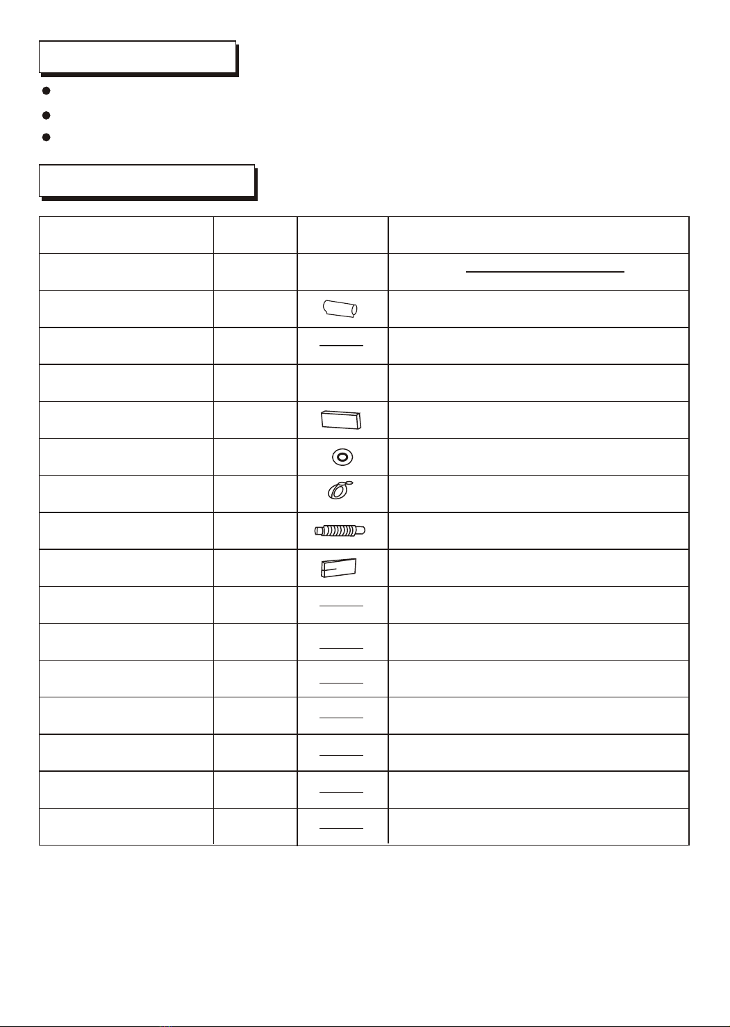
Use the attached accessories parts and specified parts for installation. Otherwise, it will
cause the set to fall, water leakage, fire or electrical shock.
Install at a strong and firm location which is able to withstand the set's weight. If the stren-
gth is not enough or installation is not properly done, the set will drop and cause injury.
For electrical work, follow the local national wiring standard, regulation and this installa-
tion instructions. An independent circuit and single outlet must be used. If electrical circuit
capacity is not enough or defect found in electrical work, it will cause electrical shock or fire.
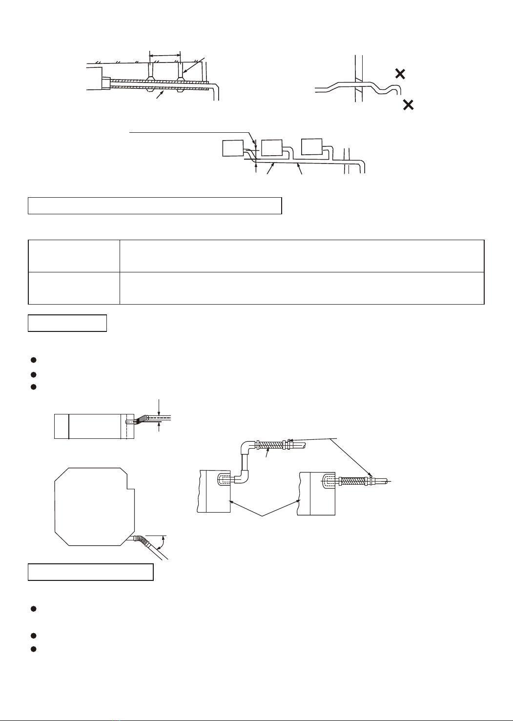
When carrying out piping connection, take care not to let air or other substances other
than the specified refrigerant go into refrigeration cycle. Otherwise, it will cause lower
capacity, abnormal high pressure in the refrigeration cycle, explosion and injury.
Grounding is necessary. It may cause electrical shock if grounding is not perfect.
Do not install the unit at place where leakage of flammable gas may occur. In case gas
leaks and accumulates at surrounding of the unit, it may cause fire.
WARNING
!WARNING
CAUTION
NOTE :
2

1.Location in the following places may cause malfunction of the machine. (If unavoidable,
please consult your local dealer)
a. A place where there is inflammable gas leakage.
b. There is salty air surrounding(near the coast).
c. There is caustic gas(the sulfide, for example) existing in the air (near a hot spring).
d. A place where can not bear the weight of the machine.
e. In kitchen where it is full of oil gas.
f. There is strong electromagnetic wave existing.
g. There is acid or alkaline liquid evaporating.
h. A place where air circulation is not enough.
2. Electrical Insulation must be done on the air conditioner and the building complying to
National Regulations.
CAUTIONS
INSTALLATION LOCATIONS
3
HEIGHT BETWEEN CEILING AND FLOOR
INSTALLATION SPACE
MDV-D28(36 45 56 71 80)Q4/N2
MDV-90(112)Q4/N2
Size A(mm) Ceiling Height
Above 315
Above 365
Models
B
C
Wall
material
Up(B)
Sides(C)
Above 10cm Above 10cm Above 10cm
Above 5cm Above 5cm
Flammable
material
Fire-proof
structure
Fire-proof material
or other nonflammable
materials other than
metal
A
Ceiling
Above 100cm Above
100cm
Above
100cm
Obstacle
MDV-D28(36)Q4/N2
MDV-D45-80Q4/N2
Height(m)
Below 2.7
Below 3.5
Models
MDV-D90-112Q4/N2
Below 4
MDV-D28(36)Q4/N2
Height(m)
Below 2.7
Below 3.5
Models
Below 4
Model (MDV-D)
2.7m<h<3m
2.7m<h<3m
3m<h<3.5m
28-36Q4/N2
45-80Q4/N2
Installation height
90-112Q4/N2

Gas side (k)f
(Liquid side fJ)
Wiring hole ( )
f38
)
Drainage pipe installation hole (f32
Humidifier hole (inside)
80 300
185
200
140
73
170
100
240
128 II
Below the ceiling
Panel Hole
Hook(on Field)
7
30
106
30
138
39
20
G
106
130
130
200
32 18
(f100)
Hole
Below the ceiling
INDOOR UNIT INSTALLATION
A
Drain side Piping side
800 (Hook-location)
D(Hook-location)
800 (Body)
C (Body)
880(Ceiling hole)
B (Ceiling hole)
940 (Panel)
A(Panel)
Please select a place where sound enough
to bear the indoor unit when installation
The Indoor Unit is possible to fall if the place
is not sound enough.
To take precautions against typhoon/earth
quake.
Be sure to install strictly according to related
specification. Wrong installation will
cause the unit to fall.
!CAUTION
4
Model(MDV-D) ABCDEF
940
1350
880
1290
820
1230
620
1030
405
610
400
605
28~36Q4/N2
71~80Q4/N2
90~112Q4/N2
GHIJKLM
260
320
536
946
130
180
f9.5
f19.0
196 136
246 186
28~45Q4/N2
56~80Q4/N2
90~112Q4/N2
Model(MDV-D)
Select installation location considering piping and wiring connection after the Indoor Unit has
been hanged. Then decide the piping wiring leading direction.
Be sure to lead the refrigerant pipes, drain pipes and connection wires out to its connection
location before hanging the unit if the opening on the ceiling has been decided.
Confirm sizes of the indoor unit and ceiling opening with the attached installation paper
pattern. (Please fix the paper pattern below the body with M5X16 screws (4).)

Hanging screw bolt
Hanging bolts
Supporting
angle steel
5
Wooden construction
Put the square timber over the roof beam,
then install the hanging screw bolts.
Timber over the beam
Roof beam
Hanging Screw
Ceiling
New Concrete Bricks
For finished concrete bricks
(Blade shape
insertion)
(Slide insertion)
Inlaying or embedding the screw bolts.
Install the hanging hook with expansible
bolt into the concrete deep to 45~50mm
to prevent loose.
Steel bar
Embedding screw bolt
(Pipe hanging and embedding
screw bolt)
Install the supporting angle steel.
Steel roof beam structure
Overhanging the indoor unit
Adjust the gasket (down side) to 138mm over the ceiling.
Hanging Bolt
Nut (Up Side)
Gasket (Up Side)
Installing Ear
Nut (Down Side)
Down side of the ceiling
Gasket (Down Side)
138mm
Bolt
Installation method should be changed under the different construction structure. Please consult
the professional for the detailed information.
After opening a hole, the ceiling should be horizontal and strong to prevent vibration.
Cut the beams at the hole and remove them.
Reinforcing the beams that have been cut and the beams fixing the ceiling .
Preparation Work on the Ceiling
1
2
CEILING HOLE AND THE HOOK INSTALLATION
Bolt with M10 whorl is to be used. The center distance between the bolts is decided by the size of the
unit . Use the following method to install:
Installation of the hanging screw bolt

PANEL INSTALLATION (SOLD SEPARATELY)
Panel installation should be done after piping and wiring.
Refer to panel installation manual for detailed information about installing the panel.
Be sure that the indoor unit and ceiling hole installation size is right before installation.
The drain pipe of indoor unit must have the heat insulation , or it will condense dew, as well as the
connections of the indoor unit.
The declivity of the drain pipe downwards should not be over 1/100, and no winding and bending.
The total length of the drain pipe when pulled out traversely shall not exceed 20m , when the
pipe is over long, a prop stand must be installed every 1.5 to 2m to prevent winding.
Refer to the following figures about the installation of the pipes.
Do not impose any pressure on the connection part of the drainage pipe.
Be sure to seal the connection parts between - and the panel - the
indoor unit ,or even small gaps may cause wind/water leakage or condensing water.
the panel the ceiling
Be sure to follow this Installation Manual during drainage installation,
the drainage pipe must have the heat insulation to prevent condensing.
CAUTION
CAUTION
DRAINAGE PIPE INSTALLATION
!CAUTION
6
Tighten nut M10
Install the hanging bolt into T groove of the hanging tool. Overhang the indoor unit and ensure
it is level using a level indicator.
Level Indicator
Hanging Screw Bolt
Hanging Screw Bolt M10
Install it down the
installing-ear
Locking Nut M10
Hanging Ear
f10 Gasket
Indoor Unit
Ceiling Installation Plate 230mm
143mm

Drainage Pipe Material, Heat-insulating Material
Flexible Hose
Connection Procedure
Core shift adjustment
o
Bend 45 C(Maximum)
Hose band
Flexible Hose
Indoor Unit
The listed material should be used:
Measure diameter of the hard pipe using cutting method, and adjust the joining angle.
Connect the transparent pipe with the polyvinyl chloride pipe.
Pull out the flexible hose, do not over deform than illustrated below.
Be sure to bind it with the attached band.
Please place the flexible hose horizontally.
Use polyvinyl chloride glue at the connection part of the drainage pipe, be sure no water
leakage.
Paste glue at the front 40mm of the polyvinyl chloride pipe, insert it into the transparent pipe.
It needs 10 minutes for the glue to dry. Do not impose pressure on the connection during the
drying period.
Drainage Pipe
Material Polyvinyl chloride pipe (f32mm outer diameter)
Foamed polyethylene insulation plate (10mm thickness)
Heat Insulation
Material
20
o
45
7
1.5m~2m
VP30
Support Bend
Up and Down
FoldLean Downward over 1/100
As long as possible about (10mm)
Lean Downward
over 1/100

Drainage Upward
Drainage Test
To make sure that the drainage pipe would not slant
downward, lead it upward to a height 360mm maximum,
then downward lead it.
Check whether the drain pipe is unhindered before testing.
1) Stow water from sprue to check.
2) Stow 600cc water with pot or hose from sprue slowly , preventing touching the drain pump motor.
3) After the preparation work , disconnect the water level switch ,power 220-240VAC to of terminal
board, and the drain pump start up immediately.
4) After drain pump run 2 min.,reset the water level pin, and the drain pump motor will stop after
running 1 min..
.
Below 360mm
Below 600mm
Below
100mm
Indoor Unit
Ceiling
8
L
N
Motor Sound Test
The drainage test is doing during checking the drain pump motor running sound .
Reset the water level switch connection to the original position after the drainage test .
Heat Insulation
Wrap the flexible hose carefully with the attached heat insulation material from the start to the
end (to indoor part)
Flexible Hose Hose band
Attached Heat-insulation
Material
Polyvinyl Chloride PipeField-arranged
Heat-insulation
Material
Drain pipe connection
Sprue

9
!CAUTION
REFRIGERANT PIPE INSTALLATION
Ventilate the air if there was any refrigerant leakage during the installation.
Make sure there is no refrigerant leakage after the installation.
Leaked refrigerant will generate poisonous gas if meeting fire.
Allowed Length and Drop of Pipes
Material and Size of the Pipes
Requirements are different when installing the outdoor unit, please refer to outdoor unit
installation manual for detailed information.
Three length (3m,5m,10m) of pipes are available to purchase.
f19
Copper Pipe for Air ConditionerPipe Material
Size(mm) Gas side
Liquid side
Refrigerant Volume to Be Added
Refrigerant volume to be added is calculated according to outdoor unit installation manual (R407C).
Be sure to add refrigerant measuring by a scale.
If the added refrigerant volume is inadequate (too much or insufficient), the compressor
malfunction will be caused. Be sure to calculate the refrigerant volume carefully.
The service man should write down the piping length and the added refrigerant volume
in the nameplate, which is on the electric control box cover of outdoor unit, for
diagnosing the compressor and refrigeration circulation malfunction.
CAUTION
f9.53
Pipe external diameter wrench torque Added wrench torque
9.5
19.0
24.5(2.5kgf.m)
98.8(10.0kgf.m)
29.4(3.0kgf.m)
117.7(12.0kgf.m)
F
F
Connection of the Refrigerant Pipe
Double-span should be used when connecting the pipes.
The wrench torque follow the below table:

10
Air Purging
Open/Close the valves
Leakage Test
Heat Insulation
Wrap to the foot of the piping
Field Piping side
Unit Body
Attached Heat Insulation Material
Use a vacuum pump, to vacuum from the gas side refrigerant adding mouth of the outdoor
unit.
Open/Close the spools or the valves of outdoor unit with a f5mm hexagon spanner.
Test if there is any leakage on the connections of the piping with soap water.
Heat insulation for the gas and liquid pipe separately.
Heat insulation should be fully and carefully done, because the liquid side pipe and gas side
pipe are easy to condense water due to low temperature when cooling.
O
Heat proof above 120 C material should be used at the gas side pipe.
The indoor unit connection parts should be no-gap heat-insulated with the attached heat insulation
materials.
Don t use the refrigerant of the outdoor unit to do the vacuum. (A certain volume of refrigerant
had been added into the outdoor unit in factory.)

11
ELECTRIC WIRING
!WARNING
Specified power cables should be used. Do not apply any pressure on the
terminals used to connect.
Grounding must be properly done.
Electric Wiring must be done by professionals. Use a separate circuit according
to national regulations.
Improper connection may cause fire.
The grounding wire should be away from gas pipes, water pipes, telephone,
lightening rods or other grounding wires. Improper grounding may cause electric
shock.
If the wiring capacity is not enough, electric shock or fire may occur.
Be sure to Install Current Leakage Protection Switch. Or electric shock may occur.
Power cord is to be selected according to national regulations.
Outdoor unit power cord should be selected and connected according to the outdoor unit
installation manual.
Wiring should be away from high temperature components, or the insulation layer of the
wires may melt down.
Use wire clamp to fix the wires and terminal block after connection.
Control wire should be wrapped together with heat insulated refrigerant pipes.
Connect the indoor unit to power only after the refrigerant has been vacuumed.
CAUTION
CAUTION
Don t connect the power wire to the signal wire connection end.

12
Indoor unit power supply and the signal wire wiring
The indoor unit power source should not be shared with outdoor unit.
The indoor units that connect to the same outdoor unit should use the same power source, creepage
protector and main switch.
The indoor power wire should be connected to the L N terminal , and the indoor/outdoor signal wire
should adopt the 2-core screened wire . The indoor /outdoor signal wire should be connected to
A B terminal and should be corresponding with the A B of the outdoor terminal. Connect the
screened layer to (E).
220-240V~ 50Hz
Outdoor Power
Supply
Indoor Power
Supply
(2-cord screened wire)
Creepage Protection
Switch
Creepage Protection
Switch
Ground Wire
380V ~
Outdoor Unit
Ground Wire
Connect to close end
of the screened wire
Indoor Unit
Indoor Unit
Wire Distribution Box
Wiring Specifications
Wiring specifications are listed below, insufficient capacity would over-heat the wire or destroy
the machine.
Model
Items
Power Cord of the Indoor Unit Control Wire
Diameter
Ground
Wire
Single-
Wire
Power
Capacity Fuse Below 20m
Twisted-pair
2-core screened wire
Twisted-pair
Below 50m
Quantity
Power Switch Power Cord
Indoor/Outdoor Unit
Signal Wire
Single Phase
220-240V~
50Hz
2
2mm 2
6mm
Not longer than 1500m
2
2mm
2
f1.5mm
15A
MDV-D28~112Q4/N2
15A
Note: This wiring specification is only for the reference ,please refer to the specified model and the
related electric standard to do the wiring.
Indoor/Outdoor
Signal wire

Indoor/Outdoor Unit Signal Wire
Terminal Board Diagram
Connect the wire according to their numbers.
Panel Wiring
Connect the Swing Motor terminal block according to the Panel Installation Manual.
Wrong connection may cause malfunction .
13
Wiring Connection
Seal the wiring connection with the insulation material , or the condensing dew will be caused.
Please refer to the indoor unit wiring diagram for the wiring.
L N
To indoor power
220-240V~50Hz Indoor/outdoor
connection wire
Please adopt the screened wire, and connect the
screened layer to (E)
P Q
Single phase indoor unit
(E)
As per the different usages to set the moving switch on the PCB in the electric control box of indoor
unit.
After the setting , be sure to cut down the main power supply switch , then turn it on again
Setting would be invalid without disconnecting the power.
CONTROL
Please number the indoor units during the installation . For example, for the first outdoor unit ,the number
of the first indoor unit is 1-1, the second indoor unit is 1-2, and the set address is 1 and 2
respectively , the others is analogical.
0
1
F
2
3
E
4
D
5
C
6
B
7
A
8
9
0
1
F
2
3
E
4
D
5
C
6
B
7
A
8
9
ENC2ENC1

14
ENC2
Toggle switch
For set horsepower
Note: The horsepower
has been set before
leaving the factory ,
anyone can t
modify it except the
maintenance person.
Code Capacity(Horsepower)
0
1
2
3
4
5
6
7
8
9
2200W(0.8HP)
14000W(5.0HP)
11200W(4.0HP)
9000W(3.2HP)
8000W(3.0HP)
7100W(2.5HP)
5600W(2.0HP)
4500W(1.5HP)
3600W(1.2HP)
2800W(1.0HP)
ENC1
TOGGLE SWITCH FOR SETTING ADDRESS
'0-F' show the address '0-F' respectively, that is, '0-15' indoor unit (together 16
units), and the others follow the analogy. If two addresses are the same in
one system , the abnormal operation will occur.

15
1
2
3
4
5
No. Typ e Contents LED Lamp flash Remarks
Mode conflict
Water level switch is
abnormal
Malfun-
ction
Malfun-
ction
Malfun-
ction
Malfun-
ction
Alarm
The evaporator sensor
check point is abnomal ,
or room temp.sensor is
abnormal.
Run lamp flashes
at 2.5Hz.
After the malfunctions
disappear, it restores
automatically.
Indoor/outdoor unit com-
munication is abnormal.
The timer lamp fla-
shes at 2.5Hz.
Condenser sensor check
point is abnormal or outdoor
temp.
sensor is abnormal.
All the indoor alarm
lamps flash at 0.5Hz.
After the malfunctions
disappear, it restores
automatically.
If the malfunctions can t
be solved in three min.
all the indoor alarm
lamps flash at 0.5Hz.
Turn off the power to restore.
Alarm lamp flashes
at 2.5Hz.
Defrost lamp
flashes at 2.5Hz.
When the indoor unit turns
to heating mode or is turned
off, the alarm will disappear.
Run lamp
Timer lamp
Defrost lamp
Alarm lamp
Manual Switch
TROUBLE SHOOTING
INSTALL ELECTRIC THROTTLE PART
Please refer to the following figures to install.
The installation size is as follows:
266
165
215
75
Electric throttle part wires group
Indoor unit input pipe
Connection pipe copper nut joint
Electric throttle part pipe joint
Indoor unit input pipe joint
Electric throttle part pipe joint
Vertically upward install
NOTE
The electric throttle part should be installed vertically upward ,the slant and invertion are not allowed.
Use two spanners to connect the electric throttle parts with indoor/outdoor pipes to avoid the copper pipe cracking.
Please pay attention to the connection orientation when connecting.(Refer to the label sticking on the electric throttle part.)
The size of electric throttle part : 215(L)X165(W)X75(H)mm.
The electric throttle part wires group connector is corresponding to the connector CN 15 on the indoor PCB.
After the malfunctions
disappear, it restores
automatically.

6292aW
This manual suits for next models
7
Table of contents
Other MDV Air Conditioner manuals
Popular Air Conditioner manuals by other brands

Dometic
Dometic BRISK AIR 579 SERIES installation instructions

Frigicoll
Frigicoll MKD-V300 Installation & owner's manual

Haier
Haier AS072AIAAA Operation manual

Mitsubishi Electric
Mitsubishi Electric Mr.Slim MS-GK36VA operating instructions

Sanyo
Sanyo THX2452 user manual

Fujitsu
Fujitsu AF Series operating manual