MDV RM2-053B-OU User manual

SERVICE MANUAL
MDV AIRCONDITIONER
SUPER DC INVERTER MULTI TYPE
RM2-053B-OU
RM3-079B-OU
RM4-108B-OU
DC MULTI OUTDOOR UNITS

1
CONTENTS
1.
General information of Outdoor Units..................................2
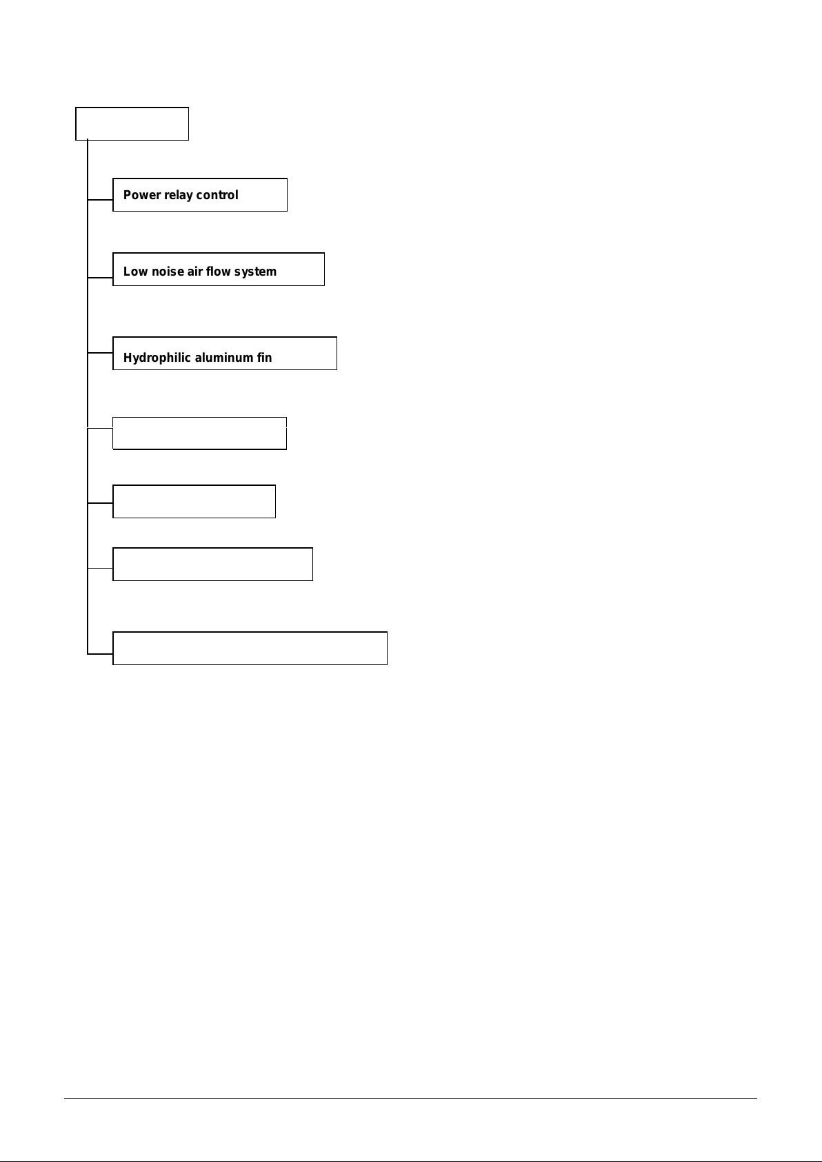
2.
Features..................................................................................3
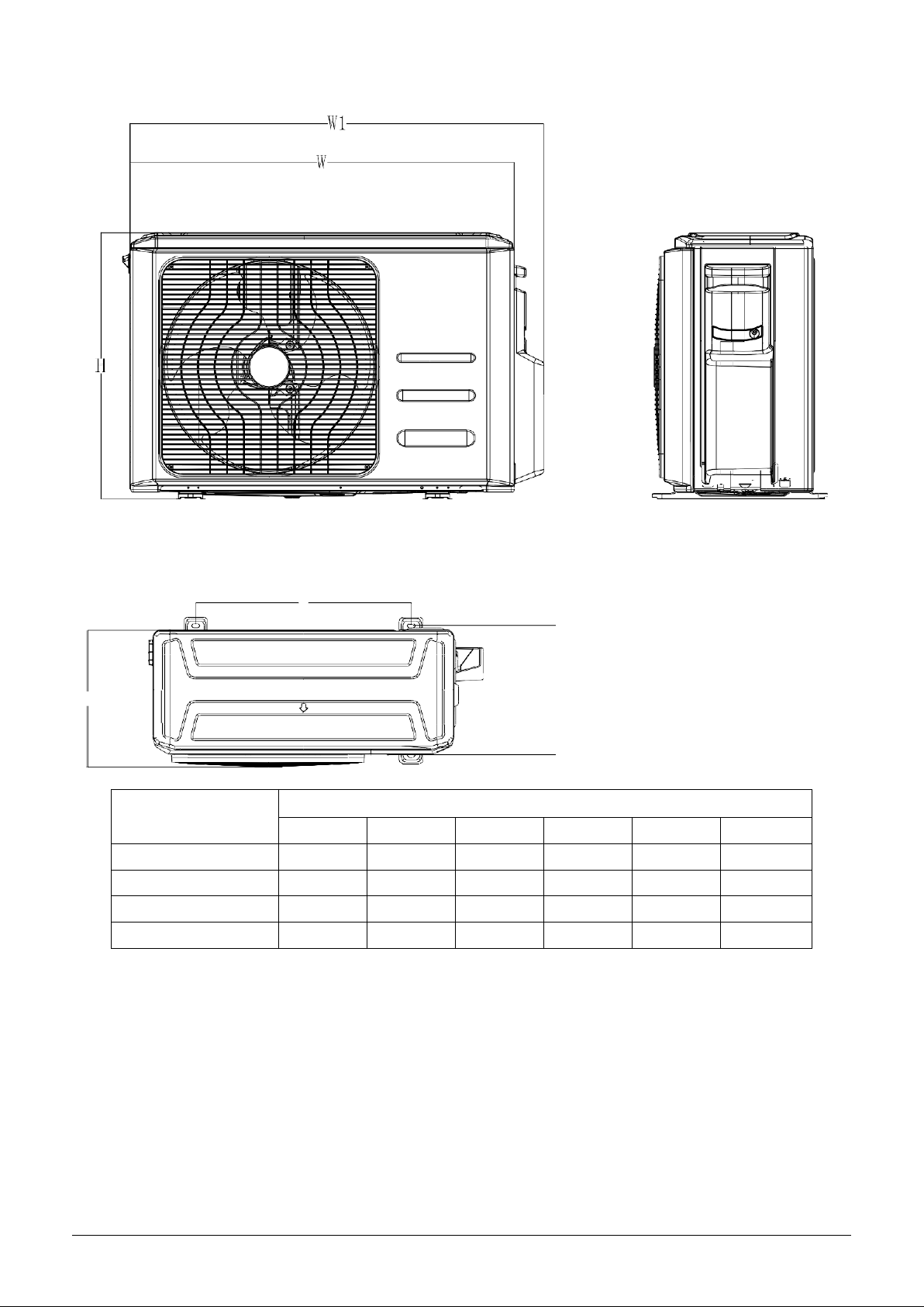
3.
Dimensions.............................................................................4
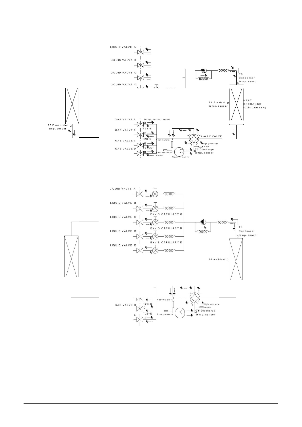
4.
Refrigeration Cycle Diagram.................................................5
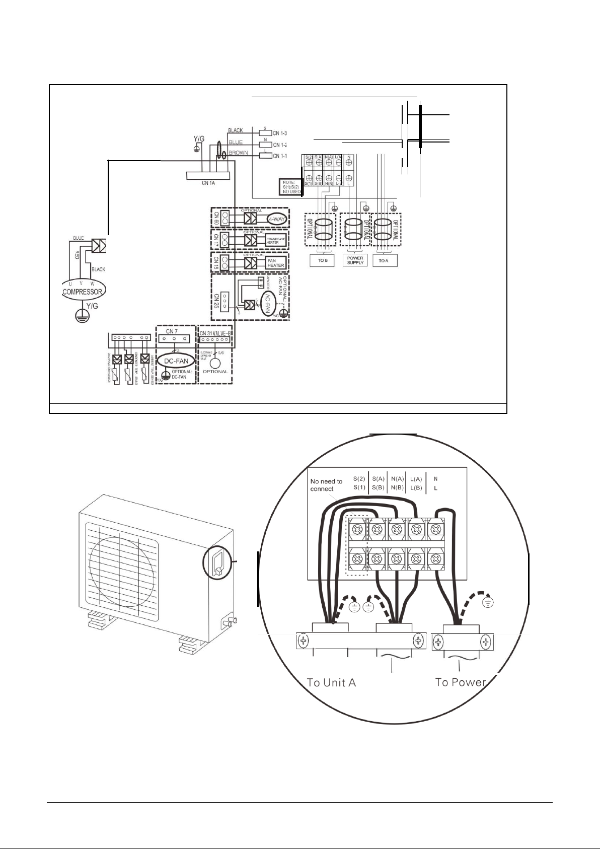
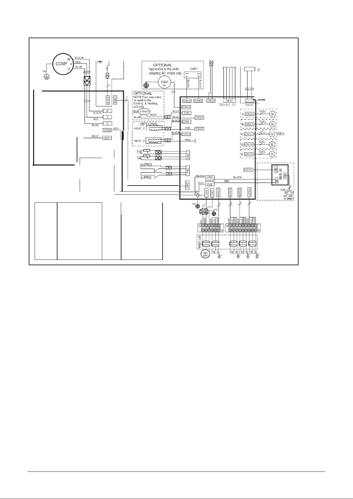
5.
Wiring diagram.......................................................................7
6.
Indoor units combination....................................................11
7.
Sound Levels........................................................................13
8.
Installation Details ...............................................................14
8.1 Wrench torque sheet for installation........................................................................... 14
8.2 Connecting the cables................................................................................................ 14
8.3 Pipe length and the elevation..................................................................................... 14
8.4 Installation for the first time......................................................................................... 15
8.5 Adding the refrigerant after running the system formany years ................................ 18
8.6 Re-installation while the indoor unit need to be repaired........................................... 19
8.7 Re-installation while the outdoor unit need to be repaired......................................... 21
9.
Electronic control function .................................................23
10.
Troubleshooting.................................................................28
Caution: Risk of fire/flammable materials

2
1. General information of Outdoor Units
Model name
Dimension (mm)
Compressor
RM2-053B-OU
800x333x554
KSM135D23UFZ
RM3-079B-OU
845x363x702
KTF235D22UMT
RM4-108B-OU
946x410x810
KTF310D43UMT

3
2. Features
the heating efficiency at operation mode.
It protects the valves and prevents water from dripping.
Power relay control
Low noise air flow system
Hydrophilic aluminum fin
The hydrophilic fin can improve
4 way valve control
Outdoor unit
It is only operated in the heating operation mode except defrosting operation.
Anti-rust cabinet
Valve protection cover
Discharge pipe temperature protection

4
3. Dimensions
A
D B
Model
Unit:mm
W
D
H
W1
A
B
RM2-053B-OU
800
333
554
860
514
340
RM3-079B-OU
845
363
702
923
540
350
RM4-108B-OU
946
410
810
1034
673
403

5
0
CAPILLARY TUBE
r
t
:i::iesensor
I
4. Refrigeration Cycle Diagram
4.1
Refrigeration circuit drawing of inverter 1 drive 2 type
IN D 0 0 R O UTDO O R
i
7
I
I
------7
CHECK VALVE
I
HEAT
EXCHANGE
r 1 Room
(EVAPORATOR)
temp. sensor
I
T2 E vaporator
□
te.m p.
sensor •
I
m
1dd
le
!
L ':t:_
T2B-A Evaporator
Co
presser
temp. sensor
H EAT
EXCHANGE
(CONDENSER)
._. COO LING
.- - - HE ATING
L _J L _ - J
4.2
Refrigeration circuit drawing of inverter 1 drive 3 type
, - - - - - - - - - - 7
- - - -
EXV A
CAPILLARY A
-------7
EXV
B CAPILLARY B CHECK VALVE
HEAT
EXCHANGE
(EVAPORATOR)
□
T 1
Room
tern p. sensor
tern
p.
sensor
HEAT
EXCHANGE
(CONDENSER)
I
T2 Evaporator 0
GAS
VALVE
A
GAS
VALVE B
I
T2B-A Evaporator
T2B-B
□
+
4 -W A Y VALVE
GAS VALVE C
I
T 2
I
L _J
I
Com presser
L_ -
. COO LING
4--- - -H E A TIN G I
J
EXV A C A P IL L A R Y A
i
B- C

6
i
7
i
7
EXV B CAPILLARY B
CHECK VALVE
EXV C CAPILLARY C
EXV D CAPILLARY D
CAPILLARY TUBE
T2B-A Evaporator
'\--C
OOLING
1&-J-i
ATI
G
4.3
Refrigeration circuit drawing of inverter 1 drive 4 type
I
N
D
O
O
R
O
U
TD
O
O
R
- - · - · -
EXV
A
CAPILLARY A
HEAT
EXCHANGE
(EVAPORATOR)
□
T
1
Room
temp. sensor
middle
4.4
Refrigeration circuit drawing of inverter 1 drive 5 type
I
N
D
O
O
R
O
UT
D
O
O
R
i 7 i
EXV A
CAPILLARY A
7
EXV
B CAPILLARY
B
CHECK VALVE
CA P IL L A R Y TUBE
HEAT
E XC H A NG E
(EVAPORATOR)
T2
Evaporator □
te_m p.
sensor
middle
!
GAS
VALVE
A
GAS VALVE B
GAS VALVE C
T 2B - A E v aporator
temp. se n sor outlet
D
t- - -
T2B-B
□
t- - -
T2 B - C
□
tern p. sensor
4-WAY VALVE
HEAT
EXCHANGE
(CONDENSER)
t---c
O OLIN G
t--
-
H
EATING
GAS VALVE E
L J
swi tch
Compressor
J
□
r
1 Room
tern
p.
sensor
-i

7
5. Wiring diagram
RM2-053B-OU
Notes: - - - - - -
This symbol indicates the element
VALVE-A
o
0
0
.
z
..
0
0
0
0
0
0
0
§t 0
w 0
0
0
r
0
n
om
O
Z o
- 0
:J;
ELECTRONIC
EXPANSIVE
is optional,the actual shape shall
VALVE
be prevail.
CN 1-2
CN2
A INDOOR PIPE
B OUT TEMP
0z
g;
CN 21
16022000026370
--
1
-
To Unit 8

8
Note: S(1)&S(2) are used in other type of models. They don't need to be connected in multi models.
RM3-079B-OU
16022300001533
RED (BROI M
BLUE
I NDDOR PI PE
OUT TEMP
OUTDOOR AMB I ENT
14 TEMPERATURE SENSOR
CN37
CONDENSER
13
TEMPERATURE SENSOR
:::r= = J
DISCHARGESENSOR
CN4
CNS
MAIN BOARD
CN2
1PM BOARD
CN3
CN1
VALVE-B
Y
0-;
ELECTRONIC
EXPANSIVE
VALVE
LECTRONIC
PANS I VE
VALVE-A Y
I\
ELECTRONIC
ANSIVE
VALVE
VE
REACTOR
0
NOTE:Us the m gneticring
i
...
L.L
1
:§
:
1
:
(
_
n
o
t
supp
li
e
d
,o
pt
1
o
a
l
pa
rt
)
:
toh1tch1heconnect1vec ble
1
:
of indoorand outdooru nits
:[..........,:!'".
:
J
afterinstallation.onemagnetic
ring isusedforonecable.
@ @
!
Y/
G
jY
/
G

9
r------------,
IApplicabletoth eunits
I
l
rv
G
,
.,
II
11
I
,
adopting
DC
motor
only
1
I
TP
16022300000894
I
I
I
I
I
I
I
I
I
I
INDOOR
PIPE OUT
TEMPA BCDE
: OLP TEMP. SENSOR
1
c::z o
:
::, a:i
r----.J
,
3
:
I
I
5 :
;t
IBi
.
i= c.. o :
a..o a::o :
r---'1-........
+---,i,,-i----+++-++-•-..
o
H-
"!
DRIVER BOARD
C N4 4
C N 53 BLACK
MAIN BOARD
BLUE
CN52
_-::::
]
..
-··
YELLOW
YELLOW
L
RM4-108B-OU
CODE
PART NAME
CODE
PART NAME
COMP
COMPRESSOR
PFC INDUCTOR
CAP1
FAN MOTOR CAPACITOR
L-PRO
LOW PRESSURE SWITCH
EEV
ELECTRIC EXPANSIVE
VALVE
TP
EXHA UST
TEMPERATURE SENSOR
FM1
OUTDOOR DC FAN
sv
4-WAY VALVE
FAN1
OUTDOOR AC FAN
T3
CONDENSER
TEMPERATURE SENSOR
HEAT
CRANKCASE HEATING
T4
OUTDOOR AMBIENT
TEMPERATURE SENSOR
H-PRO
HIGH PRESSURE SWITCH
TH
HEATSINK
TEMPERATURE SENSOR

10
CODE
PART NAME
CODE
PART NAME
COMP
COMPRESSOR
PFC INDUCTOR
CAP1
FAN MOTOR CAPACITOR
L-PRO
LOW PRESSURE SWITCH
EEV
ELECTRIC EXPANSIVE
VALVE
TP
EXHAUST
TEMPERATURE SENSOR
FM1
OUTDOOR DC FAN
sv
4-WAY VALVE
FAN1
OUTDOOR AC FAN
T3
CONDENSER
TEMPERATURE SENSOR
HEAT
CRANKCASE HEATING
T4
OUTDOOR AMBIENT
TEMPERATURE SENSOR
H-PRO
HIGH PRESSURE SWITCH
TH
HEATSINK
TEMPERATURE SENSOR

11
6. Indoor units combination
6.1
Indoor unit combination for RM2-053B-OU
One unit
Two unit
7
7+7
9+9
9
7+9
9+12
12
7+12
9+18
18
7+18
12+12
6.2
Indoor unit combination for RM3-079B-OU
One unit
Two unit
Three unit
7
7+7
9+9
12+18
7+7+7
7+9+9
7+12+18
9+12+12
9
7+9
9+12
18+18
7+7+9
7+9+12
9+9+9
9+12+18
12
7+12
9+18
7+7+12
7+9+18
9+9+12
12+12+12
18
7+18
12+12
7+7+18
7+12+12
9+9+18
6.3
Indoor unit combination for RM4-108B-OU
One unit
Two unit
Three unit
Four unit
7
7+7
9+18
7+7+7
7+9+18
9+9+12
12+12+12
7+7+7+7
7+7+9+24
7+9+12+12
9+9+12+12
9
7+9
9+24
7+7+9
7+9+24
9+9+18
12+12+18
7+7+7+9
7+7+12+12
7+9+12+18
9+9+12+18
12
7+12
12+12
7+7+12
7+12+12
9+9+24
12+12+24
7+7+7+12
7+7+12+18
7+9+18+18
9+12+12+12
18
7+18
12+18
7+7+18
7+12+18
9+12+12
12+18+18
7+7+7+18
7+7+18+18
7+12+12+12
9+12+12+18
24
7+24
12+24
7+7+24
7+12+24
9+12+18
7+7+7+24
7+9+9+9
7+12+12+18
12+12+12+12
9+9
18+18
7+9+9
7+18+18
9+12+24
7+7+9+9
7+9+9+12
9+9+9+9
12+12+12+18
9+12
7+9+12
9+9+9
9+18+18
7+7+9+12
7+9+9+18
9+9+9+12
7+7+9+18
7+9+9+24
9+9+9+18

12

13
Microphone
H
7. Sound Levels
Outdoor Unit
1.0m
Note: H= 0.5 × height of outdoor unit
Model
Noise Power dB(A)
Noise level dB(A)
RM2-053B-OU
56
53
RM3-079B-OU
65
59
RM4-108B-OU
68
63

14
8. Installation Details
8.1
Wrench torque sheet for installation
Outside diameter
Torque
Additional tightening torque
mm
N.cm
N.cm
Ф6.35
1500(153kgf.cm)
1600(163kgf.cm)
Ф9.52
2500(255kgf.cm)
2600(265kgf.cm)
Ф12.7
3500(357kgf.cm)
3600(367kgf.cm)
8.2
Connecting the cables
The power cord of connect should be selected according to the following specifications sheet.
Rated current of appliance
Nominal cross-sectional area (mm²)
>3 and ≤6
0.75
>6 and ≤10
1
>10 and ≤16
1.5
>16 and ≤25
2.5
The cable size and the current of the fuse or switch are determined by the maximum current indicated on the
nameplate which located on the side panel of the unit. Please refer to the nameplate before selecting the
cable, fuse and switch.
8.3
Pipe length and the elevation
Maximum piping length and height difference
1 drive 2
1 drive 3
1 drive 4
1 drive 5
Max. length for all rooms (m)
40
60
80
80
Max. length for one IU (m)
25
30
35
35
Max. height difference between IU and OU (m)
15
15
15
15
Max. height difference between IUs (m)
10
10
10
10
Additional refrigerant charge
1 drive 2
1 drive 3
1 drive 4
1 drive 5
Chargeless pipe
length (m)
15
22.5
30
37.5
Additional
refrigerant charge
(g)
12 x (length for all
rooms - 15)
12 x (length for all
rooms –22.5)
12 x (length for all
rooms - 30)
12 x (length for all
rooms –37.5)
Caution:
●Refrigerant pipe diameter is different according to indoor unit to be connected. When using the
extension pipe, refer to the tables below.

15
●When refrigerant pipe diameter is different from that of outdoor unit union (for 18K&24K indoor unit),
additional transfer connector needs to be used on outdoor unitunion.
Indoor unit
Extension pipe diameter (mm/inch)
Model
Pipe diameter (mm/inch)
7K9K12K
Liquid
6.35(1/4)
Liquid
6.35(1/4)
Gas
9.52(3/8)
Gas
9.52(3/8)
18K
Liquid
6.35(1/4)
Liquid
6.35(1/4)
Gas
12.7(1/2)
Gas
12.7(1/2)
24K
Liquid
9.52(3/8)
Liquid
9.52(3/8)
Gas
15.9(5/8)
Gas
15.9(5/8)
Outdoor unit union diameter (mm/inch)
1 drive 2
Liquid
6.35(1/4) *2
Gas
9.52(3/8) *2
1 drive 3
Liquid
6.35(1/4) *3
Gas
9.52(3/8) *3
1 drive 4
Liquid
6.35(1/4) *4
Gas
9.52(3/8) *3
12.7(1/2) *1
1 drive 5
Liquid
6.35(1/4) *5
Gas
9.52(3/8) *4
12.7(1/2) *1
8.4
Installation for the first time
Air and moisture in the refrigerant system have undesirable effects as below:
●Pressure in the system rises.
●Operating current rises.
●Cooling or heating efficiencydrops.
●Moisture in the refrigerant circuit may freeze and block capillarytubing.
●Water may lead to corrosion of parts in the refrigerantsystem.
Therefore, the indoor units and the pipes between indoor and outdoor units must be leak tested and
evacuated to remove gas and moisture from the system.
Gas leak check (Soap water method):
Apply soap water or a liquid neutral detergent on the indoor unit connections or outdoor unit
connections by a soft brush to check for leakage of the connecting points of the piping. If bubbles come out,
the pipes have leakage.
1. Air purging with vacuum pump

16
1) Completely tighten the flare nuts of the indoor and outdoor units, confirm that both the 2-way and 3-way
valves are set to the closed position.
2) Connect the charge hose with the push pin of handle lo to the 3-way valves gas serviceport..
3) Connect the charge hose of handle hi connection to the vacuum pump.
4) Fully open the handle Lo of the manifold valve.
5) Operate the vacuum pump to evacuate.
6) Make evacuation for 30 minutes and check whether the compound meter indicates -0.1Mpa.If
the meter does not indicate -0.1Mpa after pumping 30 minutes, it should be pumped 20 minutes more. If the
pressure can’t achieve -0.1Mpa after pumping 50 minutes, please check if there are some leakage points.
Fully close the handle Lo valve of the manifold valve and stop the operation of the vacuum pump. Confirm
that the gauge needle does not move (approximately 5 minutes after turning off the vacuum pump).
7) Turn the flare nut of the 3-way valves about 45° counterclockwise for 6 or 7seconds after the gas
coming out, then tighten the flare nut again. Make sure the pressure display in the pressure indicator is a
little higher than the atmosphere pressure. Then remove the charge hose from the 3 way valve.
8) Fully open the 2 way valve and 3 way valve and securely tighten the cap of the 3 wayvalve.
Vacuum
pump
Charge hose
Vacuum
pump
Handle Hi
Handle Lo
Charge hose
-0.1MPa gauge
Lo Hi
Close
Manifold valve
Compound meter Pressure
Three-way valve
(Gas side)
Close
Two-way valve
(Outdoor unit)
(Liquid side)
(Indoor unit)

17
2. Adding the refrigerant if the pipe length >5m
Procedure:
1). Connect the charge hose to the charging cylinder, open the 2-way valve and the 3-wayvalve.
Connect the charge hose which you disconnected from the vacuum pump to the valve at the bottom of the
cylinder. If the refrigerant is R410A, make the cylinder bottom up to ensure the liquid charge.
2). Purge the air from the charge hose.
Open the valve at the bottom of the cylinder and press the check valve on the charge set to purge the air (be
careful of the liquid refrigerant).
3) Put the charging cylinder onto the electronic scale and record theweight.
4) Operate the air conditioner at the cooling mode.
5) Open the valves (Low side) on the charge set and charge the system with liquidrefrigerant.
6).When the electronic scale displays the proper weight (refer to the table), disconnect the charge hose from
the 3-way valve’s service port immediately and turn off the air conditioner before disconnecting the hose.
7). Mount the valve stem caps and the service port
Use torque wrench to tighten the service port cap to a torque of 18N.m.
Be sure to check for gas leakage.
Electronic scale

18
8.5
Adding the refrigerant after running the system for many years
Procedure:
1). Connect the charge hose to the 3-way service port, open the 2-way valve and the 3-wayvalve.
Connect the charge hose to the valve at the bottom of the cylinder. If the refrigerant is R410A, make the
cylinder bottom up to ensure liquid charge.
2). Purge the air from the charge hose.
Open the valve at the bottom of the cylinder and press the check valve on the charge set to purge the air (be
careful of the liquid refrigerant).
3) Put the charging cylinder onto the electronic scale and record theweight.
4) Operate the air conditioner at the cooling mode.
5) Open the valves (Low side) on the charge set and charge the system with liquidrefrigerant.
6).When the electronic scale displays the proper weight (refer to the gauge and the pressure of the low side),
disconnect the charge hose from the 3-way valve’s service port immediately and turn off the air conditioner
before disconnecting the hose.
7). Mount the valve stem caps and the service port
Use torque wrench to tighten the service port cap to a torque of 18N.m.
Be sure to check for gas leakage.
Electronic scale

19
8.6
Re-installation while the indoor unit need to be repaired
1. Collecting the refrigerant into the outdoor unit
Procedure
1). Confirm that both the 2-way and 3-way valves are set to the openedposition
Remove the valve stem caps and confirm that the valve stems are in the opened position.
Be sure to use a hexagonal wrench to operate the valve stems.
2). Connect the charge hose with the push pin of handle lo to the 3-way valves gas service port.
3). Air purging of the chargehose.
Open the handle Lo valve of the manifold valve slightly to purge air from the charge hose for 5 seconds and
then close it quickly.
4). Set the 2-way valve to the close position.
5). Operate the air conditioner at the cooling cycle and stop it when the gauge indicates 0.1MPa.
6). Set the 3-way valve to the closed position immediately
Do this quickly so that the gauge ends up indicating 0.3 to 0.5Mpa.
Disconnect the charge set, and tighten the 2-way and 3-way valve’s stem nuts.
Use a torque wrench to tighten the 3-way valves service port cap to a torque of 1.8 kgf.m.
Be sure to check for gas leakage.
This manual suits for next models
2
Table of contents
Other MDV Air Conditioner manuals
Popular Air Conditioner manuals by other brands

Geostar
Geostar ASTON SERIES installation manual

CIAT
CIAT condenciat CD instruction manual

Truma
Truma Saphir comfort RC Operating and installation instruction

LG
LG Multi V PRHR042A installation manual

Hammer
Hammer Cassy Series Guide

Mitsubishi Heavy Industries
Mitsubishi Heavy Industries R410A Service manual