Tools Needed
oPhillips head screwdriver (medium size)
o1/16 hex wrench (Allen head)
o5/64 hex wrench (Allen head)
oPutty knife or other thin bladed tool
oSolvent (Alcohol)
Printed Circuit Board (PCB) Removal
WARNING
Static Electricity can damage the electronics of your telescope. Review the section on
Static Electricity prevention and electronics handling before proceeding.
1. Ensure the power to the telescope Front Panel is OFF.
2. Remove the power plug (+18V) from the Front Panel.
3. Remove the telescope from the tripod mount and/or wedge. Be very careful when
moving the telescope with the R.A. and DEC knobs locked as the motor
assemblies are engaged to their respective worm gears.
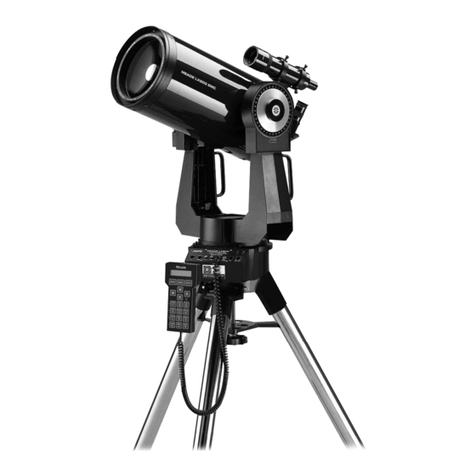
4. Carefully lay the telescope on its side on a suitable work surface.
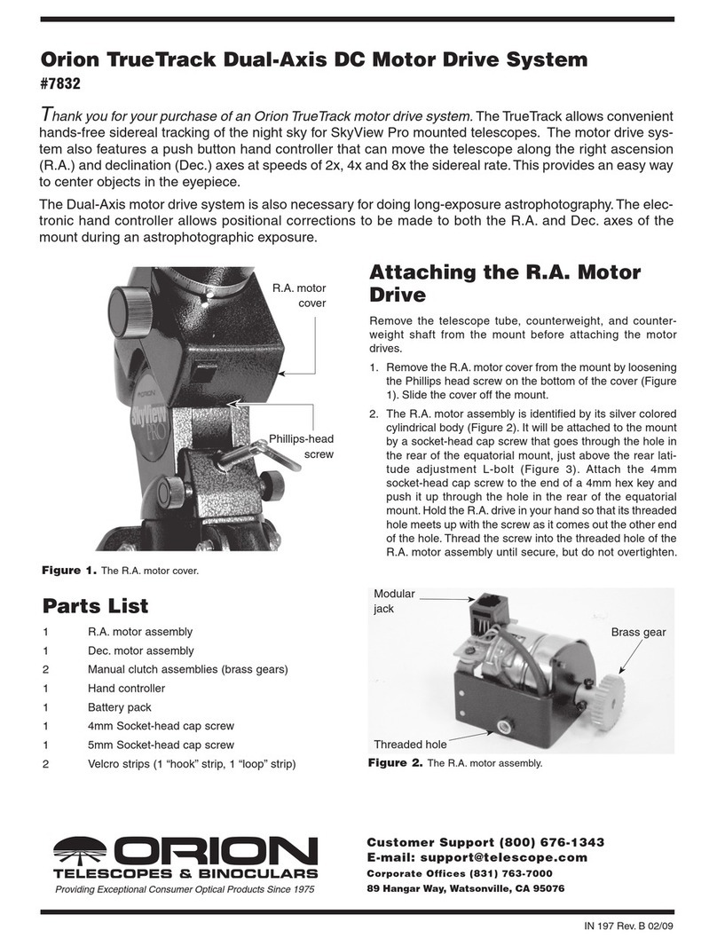
5. Unlock the R.A. and DEC knobs, orient the base as shown in Pic 1 and brace the
telescope so it cannot move.
6. Remove the drive base cover
oRemove the Phillips head screws.
oSome telescope have 4 hex screws in the middle of the cover, some have two.
oFor those bases with 4 screws, the two lager screws have clearance holes in
the cover.
oRemove the smaller 1/16” button head hex (Allen) screws.
7. Disconnect the 7 conductor motor cable from the PCB connector.
8. Disconnect the 34 conductor ribbon cable from the PCB connector. Be careful
you don’t pull too hard on the cable as you could loosen the wires where they
attach to the connector.
9. If your LX200 model has two resistors mounted to the drive base wall it is
necessary to remove the resistor mount clip from the drive base. Insert a thin
bladed tool between the drive base and the mount clip and gently pry it loose.
Leave the resistors attached.
10. Remove the PCB
oThere are six possible mounting screws holding the PCB into the base. Most
PCBs are held by four, but some use all six.
oUse a marking pen to indicate the mounting holes used by your telescope as a
reference for reinstallation.
oRemove the mounting screws and carefully pull the PCB from the base.


