Measurement Computing BTH-1208LS-OEM User manual

BTH-1208LS-OEM
Wireless Multifunction DAQ Device
Document Revision 5A
December 2014
©Copyright 2014
User's Guide

HM BTH-1208LS-OEM
Trademark and Copyright Information
Measurement Computing Corporation, InstaCal, Universal Library, and the Measurement Computing logo are
either trademarks or registered trademarks of MeasurementComputing Corporation. Refer to the Copyrights &
Trademarks section on mccdaq.com/legal for more information about Measurement Computing trademarks.
Other product and company namesmentioned herein are trademarks or trade names of their respective
companies.
©2014 MeasurementComputingCorporation. All rights reserved. No part of this publicationmay be
reproduced, stored in a retrieval system, or transmitted, in any form by any means, electronic,mechanical, by
photocopying, recording, or otherwise without the prior written permission of Measurement Computing
Corporation.
Notice
Measurement Computing Corporation does not authorize any Measurement Computing Corporation product for
use in life support systems and/or devices without prior written consent from Measurement Computing
Corporation. Life support devices/systems are devices or systems that, a) are intended for surgical implantation
into the body, or b) support or sustain life and whose failure to perform can be reasonably expected to result in
injury. Measurement Computing Corporation products are not designed with the components required, and are
not subject to the testing required to ensure a level of reliability suitable for the treatment and diagnosis of
people.

3
Table of Contents
Preface
About this User's Guide .......................................................................................................................5
What you will learn from this user's guide .........................................................................................................5
Conventions in this user's guide .........................................................................................................................5
Where to find more information.........................................................................................................................5
Chapter 1
Introducing the BTH-1208LS-OEM ......................................................................................................6
Functional block diagram...................................................................................................................................7
Chapter 2
Installing a BTH-1208LS-OEM..............................................................................................................8
Unpacking...........................................................................................................................................................8
Downloading the software..................................................................................................................................8
Pairing with the host device................................................................................................................................8
Installing the hardware in USB mode (Windows only)......................................................................................9
Configuring Bluetooth settings...........................................................................................................................9
Calibrating the hardware.....................................................................................................................................9
Chapter 3
Functional Details ...............................................................................................................................10
Analog input acquisition modes .......................................................................................................................10
Software paced mode.......................................................................................................................................................10
Hardware paced mode......................................................................................................................................................10
BURSTIO........................................................................................................................................................................11
Board components............................................................................................................................................11
USB connector.................................................................................................................................................................11
Power/pairing button........................................................................................................................................................12
LEDs................................................................................................................................................................................12
Connector J1....................................................................................................................................................................13
Connector J2....................................................................................................................................................................13
Connector J3....................................................................................................................................................................13
Signal connections............................................................................................................................................14
Analog input....................................................................................................................................................................14
Analog output ..................................................................................................................................................................15
External clock input.........................................................................................................................................................15
Digital I/O........................................................................................................................................................................15
External pull-up/pull-down capability .............................................................................................................................15
Bulkhead signals..............................................................................................................................................................16
Trigger input....................................................................................................................................................................16
Counter input...................................................................................................................................................................16
Ground.............................................................................................................................................................................17
Power output....................................................................................................................................................................17
Mechanical drawing .........................................................................................................................................17
Chapter 4
Specifications......................................................................................................................................18
Analog input.....................................................................................................................................................18
Accuracy..........................................................................................................................................................................19
Noise performance...........................................................................................................................................................20
Analog output...................................................................................................................................................20
Digital input/output...........................................................................................................................................21
External trigger.................................................................................................................................................22
External clock input..........................................................................................................................................22

BTH-1208LS-OEM User's Guide
4
Counter.............................................................................................................................................................23
Memory ............................................................................................................................................................23
Microcontroller.................................................................................................................................................23
Power................................................................................................................................................................24
Bluetooth ..........................................................................................................................................................24
USB ..................................................................................................................................................................24
Environmental ..................................................................................................................................................24
Mechanical .......................................................................................................................................................25
Signal connectors..............................................................................................................................................25
Analog signals (J1) ..........................................................................................................................................................25
Digital signals (J2)...........................................................................................................................................................25
Bulkhead signals (J3).......................................................................................................................................................26

5
Preface
About this User's Guide
What you will learn from this user's guide
This user's guide describes the Measurement Computing BTH-1208LS-OEM wireless data acquisition device
and lists device specifications.
Conventions in this user's guide
For more information
Text presented in a box signifies additional information and helpful hints related to the subject matter you are
reading.
Caution! Shaded caution statements present information to help you avoid injuring yourself and others,
damaging your hardware, or losing your data.
bold text Bold text is used for the names of objects on a screen, such as buttons, text boxes, and check boxes.
italic text Italic text is used for the names of manuals and help topic titles, and to emphasize a word or phrase.
Where to find more information
Additional information about the BTH-1208LS-OEM is available on our website at www.mccdaq.com. You can
also contact Measurement Computing Corporation with specific questions.
Knowledgebase: kb.mccdaq.com
Tech support form: www.mccdaq.com/support/support_form.aspx
Email: techsupport@mccdaq.com
Phone: 508-946-5100 and follow the instructions for reaching Tech Support
For international customers, contact your local distributor. Refer to the International Distributors section on our
website at www.mccdaq.com/International.

6
Chapter 1
Introducing the BTH-1208LS-OEM
The BTH-1208LS-OEM is a multifunction data acquisition device that communicates using Bluetooth®
wireless technology.
The Bluetooth radio host used with the device must support Bluetooth 2.0 or later. The following Bluetooth
stack protocols are supported on Windows:
Microsoft Bluetooth stack
Broadcom ® Bluetooth stack (not supported by Windows XP)
The device supports USB 2.0 full-speed when connected to a USB port. The device is also compatible with
USB 1.1 ports; however, the speed of the device may be limited when using a USB 1.1 port due to the
difference in transfer rates on USB 1.1 versions of the protocol (low-speed and full-speed).
The BTH-1208LS-OEM provides the following features:
Eight 11-bit single-ended (SE) or four 12-bit differential (DIFF) analog input channels
1 kS/s max sample rate in Bluetooth continuous scan mode
47 kS/s sample rate in Bluetooth BURSTIO mode and when communicating over USB connection
Software-selectable analog input ranges of ±10 V (SE), and ±20 V, ±10 V, ±5 V, ±4 V, ±2.5 V, ±2.0 V,
±1.25 V, and ±1.0 V (DIFF).
Two 12-bit analog outputs
Eight individually-configurable digital I/O channels
One 32-bit event counter
One external digital trigger input
One external clock input
Three header connectors for field wiring
Header connectors available for user-supplied power; can also be powered by a USB power supply in
Bluetooth mode or from the USB host device in USB mode. Connectors for battery power and battery
charging are also included.
Caution! There are no product safety, electromagnetic compatibility (EMC), or CE marking compliance
claims made for the BTH-1208LS-OEM. The BTH-1208LS-OEM is intended for use as a
component of a larger system. MCC can help developers meet their compliance requirements. The
end product supplier, however, is responsible for conforming to any and all compliance
requirements.

BTH-1208LS-OEM User's Guide Introducing the BTH-1208LS-OEM
7
Functional block diagram
BTH-1208LS-OEM functions are illustrated in the block diagram shown here.
Figure 1. Functional block diagram
2
Microcontroller
8
Analog Input
8 Single-Ended Channels (11-bit)
or
4 Differential Channels (12-bit)
Analog Output
2 Channels
J1
J3
Bluetooth
Module
USB
Power Supplies
with Shutdown and Soft-Start
Charger
Control
3.3 V
1.8 V
to
5.5 V
Digital I/O
Trigger Input
8
Event Counter
1 Channel
(32-bit)
J2
1
Clock Input

8
Chapter 2
Installing a BTH-1208LS-OEM
Unpacking
As with any electronic device, you should take care while handling to avoid damage from static
electricity. Before removing the board from its packaging, ground yourself using a wrist strap or by simply
touching the computer chassis or other grounded object to eliminate any stored static charge.
Downloading the software
Refer to the BTH-1208LS-OEM product page on the Measurement Computing website for information about
the supported software you can download.
For instructions on deploying and running apps in an Android environment, refer to the UL for Android
Example Projects topic in the Universal Library for Android Help that installs with the UL for Android
software library.
Install the software before you install the hardware
The driver needed to run the device is installed when you install the software. Therefore, you need to install the
software package you plan to use before you install the hardware.
Pairing with the host device
Pairing creates a bond between a Bluetooth device and a host device. A host device can be either a Windows-
based computer or an Android device (tablet, phone, or mini-PC).
The BTH-1208LS-OEM must be paired with the host device before it can establish a wireless connection and
transmit acquired data to the device. A BTH-1208LS-OEM only has to be paired once with a particular host
device.
The BTH-1208LS-OEM can be paired or connected when powered by:
batteries (standard or rechargeable)
an external USB power supply
The BTH-1208LS-OEM cannot be paired when powered by a USB host device.
To pair the BTH-1208LS-OEM as a Bluetooth device, make sure the device is not connected to a USB host, and
complete the following steps (refer to Figure 2 on page 11 for the location of device components referenced in
this section):
1. Make sure the host device is configured to host a Bluetooth device. Refer to host device documentation to
learn how to enable Bluetooth and how to search for and pair with Bluetooth devices.
2. If powered by batteries, press and hold the button for at least five seconds to power on the device and put it
into pairing mode.
If powered by a USB power supply, press and hold the button for at least three seconds to put the device
into pairing mode.
When the Power and Status LEDs blink alternately, the device is in pairing mode and is ready to pair with
the host device.
3. Select the Bluetooth device setup in the host device OS software, and then select the BTH-1208LS-OEM
when it displays. Refer to the Bluetooth documentation of your host device to learn how to pair it with a
Bluetooth device.
For example, in Windows, select Bluetooth Devicefrom the Control Panel, and then double-click on
BTH-1208LS-OEM-xxxx in the Add a device dialog box (xxxx are the last four digits of the device serial
number. You may need to wait a few seconds for the device to display.
4. If host device requests a passkey, PIN or pairing code, enter the default value for the device (0000).

BTH-1208LS-OEM User's Guide Installing a BTH-1208LS-OEM
9
5. Press and hold the power/pairing button for two seconds to remove the device from pairing mode.
Once the BTH-1208LS-OEM is paired to the host device, run an application that communicates with the device
(such as InstaCal or a UL for Android example program) to establish a connection. The Status LED turns on to
indicate a Bluetooth connection is established.
Digital ground to earth ground connection recommended
Measurement Computing recommends that you connect one of the digital grounds (GND) to earth ground to
reduce the chance of the BTH-1208LS-OEM unexpectedly powering down due to electrostatic discharge.
Installing the hardware in USB mode (Windows only)
The driver needed to run the BTH-1208LS-OEM device is installed when you install the software. Therefore,
you need to install the software package you plan to use before you install the hardware. For operation on a
Windows operating system, Measurement Computing recommends that you run Windows Update to update
your operating system with the latest USB drivers.
Connect the USB cable to an available USB port on the computer or to an external USB hub connected to the
computer. Connect the other end of the USB cable to the USB connector on the device. No external power is
required.
Configuring Bluetooth settings
All Bluetooth settings except for the pairing code can be changed when the BTH-1208LS-OEM is either
physically or wirelessly connected to the host device. The pairing code can only be changed when the BTH-
1208LS-OEM is physically connected to the host device.
You can configure the following Bluetooth settings on the BTH-1208LS-OEM through software. For example,
if you are using the device in a Windows environment, you can configure these settings with InstaCal.
Pairing code – Four digit code that identifies the BTH-1208LS-OEM to the host device (default = 0000).
The pairing code cannot be changed when the BTH-1208LS-OEM is connected wirelessly to the host
device.
Bluetooth connection status notifications – You can set values that indicate when the device is
connected over Bluetooth, and when the Bluetooth connection terminates. Connected and disconnected
values can be set for digital outputs, analog output channel 0, and analog input channel 1
Auto shutdown – When the device is powered by batteries, you can configure the device to power down a
specified amount of time after the Bluetooth connection terminates.
Battery charging – When the device is powered by rechargeable batteries, you can configure the device to
recharge batteries from the USB power supply when connected over Bluetooth.
Calibrating the hardware
The Measurement Computing Manufacturing Test department performs the initial factory calibration. Return
the device to Measurement Computing Corporation when calibration is required. The recommended calibration
interval is one year.
Field calibration is not supported.

10
Chapter 3
Functional Details
Analog input acquisition modes
The BTH-1208LS-OEM can acquire analog input data in three different modes – software paced, hardware
paced, and BURSTIO.
Software paced mode
In software paced mode you can acquire one analog sample at a time. You initiate the A/D conversion by
calling a software command. The analog value is converted to digital and returned to the computer. You repeat
this procedure until you have the total number of samples that you want from one channel.
When communicating over a Bluetooth connection, the typical throughput sample rate in software paced
mode is 10 S/s (system-dependent).
When communicating over a USB connection, the typical throughput sample rate in software paced mode
is 250 S/s (system-dependent).
Hardware paced mode
In hardware paced mode you can acquire data from up to eight channels. The analog data is acquired and
converted to digital values until you stop the scan.
When communicating over a Bluetooth connection, the maximum sample rate of 1024 S/s is an aggregate
rate. The total acquisition rate for all channels cannot exceed 1024 S/s. The following table lists the sample
rates when scanning from one to eight channels in Bluetooth mode.
Maximum per channel sample rate in Bluetooth mode
# channels scanned Sample rate (S/s)
1 1024
2 512
3 341.33
4 256
5 204.8
6 170.67
7 146.28
8 128
When communicating over a USB connection, the maximum sample rate of 47 kS/s is an aggregate rate.
The total acquisition rate for all channels cannot exceed 47 kS/s. Data is transferred in blocks of 32 samples
from the device to the memory buffer on your computer.
The following table lists the sample rates when scanning from one to eight channels in USB mode.
Maximum per channel sample rate in USB mode
# channels scanned Sample rate (kS/s)
1 47
2 23.5
3 15.67
4 11.75
5 9.40
6 7.83
7 6.70
8 5.88

BTH-1208LS-OEM User's Guide Functional Details
11
In both Bluetooth mode and USB mode, you can start a hardware-paced scan with either a software command
or with an external hardware trigger event.
BURSTIO
When using BURSTIO, the BTH-1208LS-OEM can acquire data at the maximum throughput of 47kS/s when
connected in Bluetooth mode. BURSTIO doesn’t offer any advantage in USB mode, since these rates are
supported for BLOCKIO in USB mode.
When BURSTIO is enabled, scans are limited to the depth of the onboard memory (12,288 samples), as the data
is acquired at a rate faster than it can be transferred to the computer. Keep in mind that when using Bluetooth,
the rate of transfer of the acquired data to the host is still limited, so the process can take several seconds. Time
must be allowed between scans for the acquisition and the transfer of the data.
The maximum sample rate is an aggregate rate. The total sample rate using BURSTIO is 47 kS/s per channel for
any or all channels. An error occurs if you exceed the FIFO capacity and acquire more than 12,288 samples in
BURSTIO mode.
Board components
The BTH-1208LS-OEM has the following components, as shown in Figure 2.
1 Connector J2 4 USB connector
2 Connector J3 5 Power/Pairing Button
3 Connector J1 6 Power LED (top) and Status LED (bottom)
Figure 2. Board components
USB connector
The USB connector provides 5 V power when connected to a USB power supply, and provides both power and
communication when the device is connected to a USB port. If rechargeable NiMH or NiCd batteries are
powering the device, recharges batteries when connected to USB host or power supply.

BTH-1208LS-OEM User's Guide Functional Details
12
Power/pairing button
The power/pairing button has different functions depending on the power source of the device.
The term pairing refers to one function of the button – to put the device in pairing mode so it can establish an
association between the Bluetooth radio on the host device and the BTH-1208LS-OEM radio.
Button functions are listed in the table below.
Power/pairing button functions
Power Status Button Functions
Battery powered To power on the device, press and hold the button for 3 seconds. To enter pairing mode,
hold the button for an additional 2 seconds.
To remove the device from pairing mode, press and hold the button again for 2 seconds.
To power off the device when not in pairing mode, press and hold the button for 2 seconds
Powered by USB
charger/USB power
supply
To put the device in pairing mode when it is powered on, press and hold button for 2
seconds.
To remove the device from pairing mode, press and hold the button again for 2 seconds.
Powered by USB host
port or hub The power/pairing button is disabled.
LEDs
The Power LED indicates the power status of the device. The Status LED indicates the communication status of
the device.
LEDs cannot be disabled. LED states are listed in the tables below.
Power and Status LED behavior
Power LED Indication
Steady green The device is powered by USB and the batteries are sufficiently charged or not installed.
Blinks continuously Connected to USB port/host: the batteries are recharging (only if rechargeable batteries are
installed).
The device is not connected to a USB port: indicates battery power
The Power LED blinks alternately with the Status LED: the device is in pairing mode.
Off Device is off.
Status LED Indication
Steady green Bluetooth or USB connection established
Blinks continuously Communication with host computer over a Bluetooth or USB connection.
The Status LED blinks alternately with the Power LED: the device is in pairing mode.
Off A Bluetooth or USB connection is not established

BTH-1208LS-OEM User's Guide Functional Details
13
Connector J1
Header connector J1 provides connections for the analog inputs, analog outputs, and analog ground reference.
Refer to Figure 5 on page 17 for the location and orientation of J1.
Four-channel differential mode
Pin Signal name Pin description Pin Signal name Pin description
1 CH0H Analog input 0 HI 2 AGND Analog ground
3 CH0L Analog input 0 LO 4 AGND Analog ground
5 CH1H Analog input 1 HI 6 AGND Analog ground
7 CH1L Analog input 1 LO 8 AGND Analog ground
9 CH2H Analog input 2 HI 10 AGND Analog ground
11 CH2L Analog input 2 LO 12 AGND Analog ground
13 CH3H Analog input 3 HI 14 AOUT0 Analog output 0
15 CH3L Analog input 3 LO 16 AOUT1 Analog output 1
Eight-channel single-ended mode
Pin Signal name Pin description Pin Signal name Pin description
1 CH0 IN Analog input 0 2 AGND Analog ground
3 CH1 IN Analog input 1 4 AGND Analog ground
5 CH2 IN Analog input 2 6 AGND Analog ground
7 CH3 IN Analog input 3 8 AGND Analog ground
9 CH4 IN Analog input 4 10 AGND Analog ground
11 CH5 IN Analog input 5 12 AGND Analog ground
13 CH6 IN Analog input 6 14 AOUT0 Analog output 0
15 CH7 IN Analog input 7 16 AOUT1 Analog output 1
Connector J2
Header connector J2 provides connections for the DIO, external clock input, trigger, counter, power output, and
digital ground reference. Refer to Figure 5 on page 17 for the location and orientation of J2.
Pin Signal name Pin description Pin Signal name Pin description
1 DIO0 Digital input/output 0 2 GND Digital ground
3 DIO1 Digital input/output 1 4 CTR Counter input
5 DIO2 Digital input/output 2 6 TRIG_IN Digital trigger input
7 DIO3 Digital input/output 3 8 AICKI Pacer input
9 DIO4 Digital input/output 4 10 GND Digital ground
11 DIO5 Digital input/output 5 12 +VO 3.3V output
13 DIO6 Digital input/output 6 14 GND Digital ground
15 DIO7 Digital input/output 7 16 GND Digital ground
Connector J3
Header connector J3 provides connections for bulkhead signals. Refer to Figure 5 on page 17 for the location
and orientation of J3.
Pin Signal name Pin description Pin Signal name Pin description
1 BATT+ Battery input positive
(2 AA/AAA cells) 2 BATT– Battery input negative
3 BATT_MID Battery center tap 4 GND Ground
5 THERMISTOR+ 10 kΩthermistor positive
(battery temperature sensing) 6 THERMISTOR– 10 kΩthermistor negative
7 PWR SW+ SPST contact 1 (power switch) 8 PWR SW – SPST contact 2
9 PAIRING SW+ Momentary contact 1 (pairing /
soft power switch) 10 PAIRING SW– Momentary contact 2
11 LED1+ LED1 anode 12 LED1 – LED1 cathode
13 LED2+ LED2 anode 14 LED2 – LED2 cathode
15 Vbus USB 5V supply (charging LED
anode) 16 CHARGE LED – Charging LED cathode
BTH-1208LS-OEM User's Guide Functional Details
14
Signal connections
Analog input
You can connect up to eight single-ended analog input connections (CH0 to CH7) or four differential
connections (CH0H/CH0L to CH3H/CH3L) on connector J1.
Single-ended configuration
When configured for single-ended input mode, eight analog input channels are available. Each analog input has
11-bit resolution (due to restrictions imposed by the A/D converter) and offers a ±10 V analog input range.
The input signal is referenced to signal ground (AGND), and is delivered through two wires:
Connect the wire carrying the signal to be measured to CHx.
Connect the second wire to AGND.
Single-ended measurements using differential channels
To perform a single-ended measurement using differential channels, connect the signal to the CHxHinput, and
ground the associated CHxL input.
Differential configuration
When the analog input channels are configured for differential input mode, four analog input channels are
available. A low-noise precision programmable gain amplifier (PGA) is available on differential channels. Each
analog input has 12-bit resolution and offers software-selectable analog input ranges of ±20 V, ±10 V, ±5 V, ±4
V, ±2.5 V, ±2.0 V, ±1.25 V, and ±1.0 V.
In differential mode, the input signal is measured with respect to the low input. The input signal is delivered
through three wires:
Connect the wire carrying the signal to be measured to CHxH.
Connect the wire carrying the reference signal to CHxL.
Connect the third wire to AGND.
In differential mode, the following two requirements must be met for linear operation:
Any analog input must remain in the −10 V to 20 V range with respect to ground at all times.
The maximum differential voltage on any analog input pair must remain within the selected voltage range.
Channel gain queue
The channel gain queue feature allows you to set up a scan sequence with a unique per-channel gain setting and
channel sequence. The gain settings are stored in a channel-gain queue list that is written to local memory on
the device.
The channel-gain queue list can contain up to up to 8 elements in single-ended mode or four elements in
differential mode. The elements must be unique and listed in ascending order. An example of a three-element
list is shown in the table below.
Sample channel gain queue list
Element Channel Range
0 CH0 BIP10V
1 CH2 BIP5V
2 CH3 BIP10V
When a scan begins with the gain queue enabled, the BTH-1208LS-OEM reads the first element, sets the
appropriate channel number and range, and then acquires a sample. The properties of the next element are then
retrieved, and another sample is acquired. This sequence continues until all elements in the gain queue have
been selected. When the end of the channel list is detected, the sequence returns to the first element in the list.
This sequence repeats until the specified number of samples is acquired.
BTH-1208LS-OEM User's Guide Functional Details
15
Carefully match the gain to the expected voltage range on the associated channel or an over range condition
may occur. Although this condition does not damage the device, it does produce a useless full-scale reading,
and can introduce a long recovery time due to saturation of the input channel.
Analog output
Two 12-bit analog outputs are available at AOUT0 and AOUT1 on connector J1.
Each analog output channel has an output range of 0 V to 2.5 V. Throughput is system-dependent.
The D/A is software paced.
External clock input
The BTH-1208LS-OEM provides one external clock input for the analog input pacer. You can connect an
external clock signal to AICKI on connector J2.
Digital I/O
You can connect up to eight digital I/O lines to DIO0 through DIO7. The digital I/O terminals can detect the
state of any TTL-level input.
Digital input voltage ranges of up to 0 to 5.5 V are permitted, with thresholds of 0.8 V (low) and 2.0 V (high).
Each DIO channel is an open-drain, which can sink up to 50 mA for direct drive applications when used as an
output.
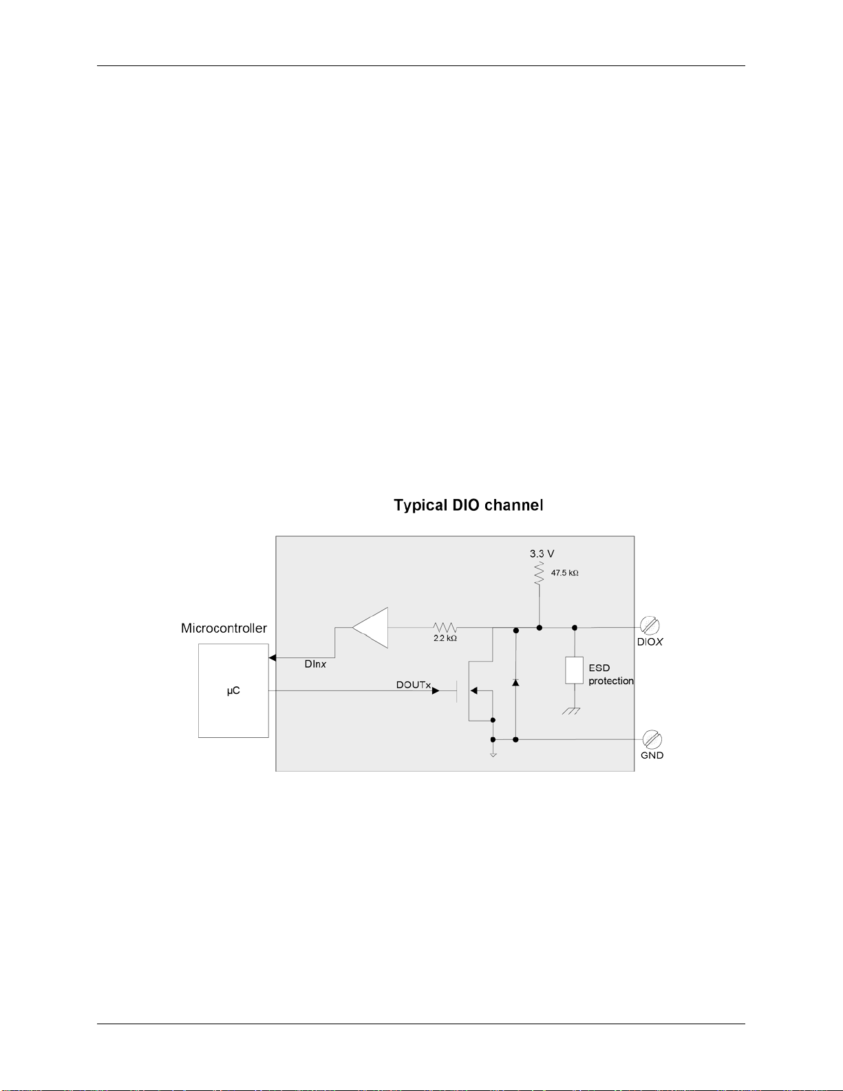
Figure 3 shows an example of a typical DIO connection. The figure represents connections for one channel. The
other seven channels are connected in the same manner.
Figure 3. Digital output connection example
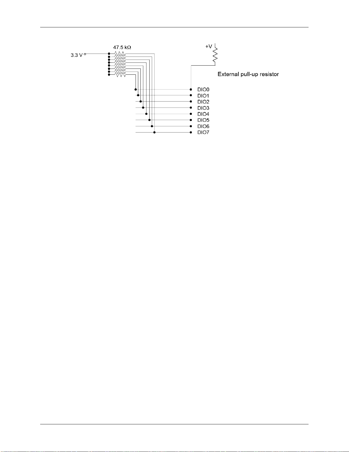
External pull-up/pull-down capability
Inputs are pulled high by default to 3.3 V through 47.5 kΩ resistors on the circuit board. The pull-up voltage is
common to all 47.5 kΩ resistors.
You can place an external pull-up resistor on any of the DIO bits in order to limit source current to less than 50
mA., which requires a 100 Ωresistor minimum. A 2 kΩor 5 kΩresistor would be typically used, allowing for a
1 mA current
You can also use an external pull-up resistor to pull the DIO bit up to a voltage that exceeds the internal 3.3 V
pull-up voltage (5.5 V maximum).
When using external pull-up resistors, be aware that the internal resistors cause a slight voltage shift to digital
lines in the on state as various lines change between the on/off states.
BTH-1208LS-OEM User's Guide Functional Details
16
Figure 4. Digital I/O external resistor configuration
Bulkhead signals
The function of the bulkhead pins is explained below.
Battery charging
Use the BATT+, BATT_MID, and BATT– pins to charge two AA or AAA cells used in series, with
BATT_MID connected to the midpoint of the series cells. This enables the charger to detect the voltage of the
cells independently in order to stop fast charging when either cell reaches full capacity.
Also you must use the THERMISTOR+ and THERMISTOR– pins to connect to a 10 kΩ thermistor in close
proximity to the battery cells to monitor battery temperature.
External power supply (battery charging not required)
Use the BATT+ and BATT– pins to supply power to the board when battery charging is not required. Power
can be supplied from any DC source in the 1.8 V to 5.5 V range.
Power and pairing control
Use the PWR_SW+ and PWR_SW– pins with an external SPST power switch to turn the board on and off.
Use the PAIRING_SW+ and PAIRING_SW– with a momentary switch to perform the same power and pairing
functionality as the onboard button (refer to Power/pairing button on page 12).
LED control
Use the LED1+ and LED1– pins to connect an external power LED. The series resistor is already on the
BTH-1208LS-OEM; only a LED is required.
Use the LED2+ and LED2– pins to connect an external status LED. The series resistor is already on the
BTH-1208LS-OEM; only a LED is required.
Use the Vbus pin to connect to an external charging LED or to power external circuits from a +5 V supply when
a USB host or power supply is present.
Use the CHARGE_LED– pin in combination with the Vbus pin for an external charging LED. The series
resistor is already on the BTH-1208LS-OEM; only a LED is required.
Trigger input
The TRIG_IN pin on connector J2 is an external digital trigger input that you can configure for either
rising/falling edge, or high/low level.
Counter input
The CTR pin on connector J2 is a 32-bit event counter that can accept frequency inputs up to 1 MHz. The
internal counter increments when the TTL levels transition from low to high.
BTH-1208LS-OEM User's Guide Functional Details
17
Ground
The analog ground (AGND) pin on connector J1 provide a common ground for all analog channels. The ground
(GND) pins on connector J2 provide a common ground for the digital, trigger, counter, and power terminals.
Power output
The +VO pin on connector J2 is a 3.3 V output that can source up to 50 mA that is supplied by the power source
of the device. You can use this terminal to supply power to external devices or circuitry.
Caution! The +V0 pin is an output. Do not connect to an external power supply or you may damage the
BTH-1208LS-OEM and possibly the computer.
For more information about signal connections
For more information about analog and digital signal connections, refer to the Guide to DAQ Signal
Connectionsat www.mccdaq.com/pdfs/DAQ-Signal-Connections.pdf.
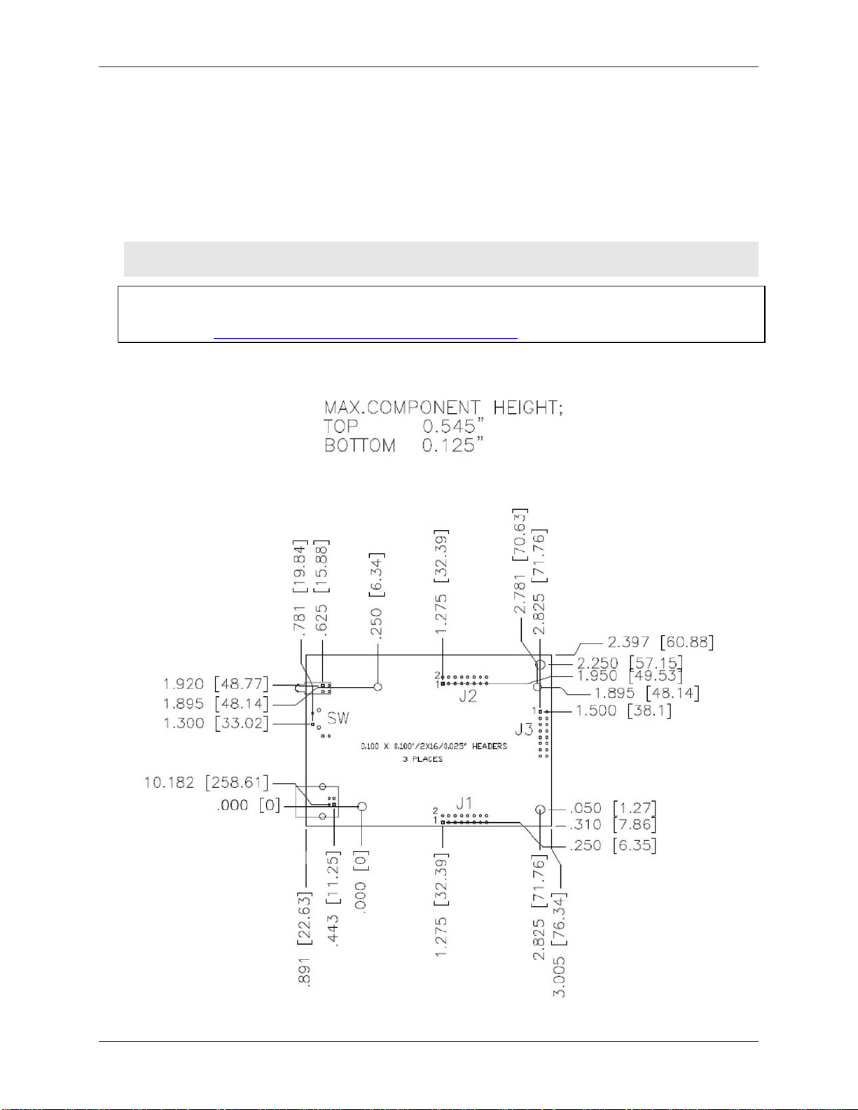
Mechanical drawing
Figure 5. Circuit board dimensions

Chapter 4
Specifications
All specifications are subject to change without notice.
Typical for 25°C unless otherwise specified.
Specifications in italic text are guaranteed by design.
Analog input
Table 1. Analog input specifications
Parameter Condition Specification
A/D converter type Successive approximation type
Input voltage range for linear operation CHx to GND Single-ended mode: ±10 V max
Differential mode: –10 V min, +20 V max
Absolute maximum input voltage CHx to GND ±25 V max
Input impedance 140 kΩ
Input current (Note 1) Vin = +10 V 70 µA typ
Vin = 0 V –12 µA typ
Vin = –10 V –94 µA typ
Number of channels 8 single-ended or 4 differential; software-selectable
Input ranges Single-ended ±10 V, G=2
Differential ±20 V, G=1
±10 V, G=2
±5 V, G=4
±4 V, G=5
±2.5 V, G=8
±2.0 V, G=10
±1.25 V, G=16
±1.0 V, G=20
Software-selectable
Throughput (Note 2) Software paced 10 S/s typ, system-dependent (Bluetooth)
250 S/s typ, system-dependent (USB)
Continuous scan 0.014 S/s to 1024 S/s (Bluetooth)
0.014 S/s to 47 kS/s (USB)
BURSTIO 0.014 S/s to 47 kS/s to 12K (12,288) sample FIFO
Transfer rate to host is limited to 1024 S/s
(Bluetooth)
Channel gain queue Software selectable. 8 elements in SE mode,
4 elements in DIFF mode.
One gain element per channel. Elements must be
unique and listed in ascending order.
Resolution (Note 3) Differential 12 bits, no missing codes
Single-ended 11 bits
Integral linearity error ±1 LSB typ
Differential linearity error ±0.5 LSB typ
Repeatability ±1 LSB typ
Trigger source Software-selectable External digital: TRIG
Software-selectable
Pacer source Software-selectable Internal
External (AICKI), rising edge triggered
Software-selectable

BTH-1208LS-OEM User's Guide Specifications
19
Note 1: Input current is a function of applied voltage on the analog input channels. For a given input
voltage, Vin, the input leakage is approximately equal to (8.181 * Vin– 12) µA.
Note 2: Maximum throughput when scanning is machine dependent.
Note 3: The AD7870 converter only returns 11 bits (0 to 2,047 codes) in single-ended mode.
Accuracy
Table 2. Accuracy, differential mode
Range Accuracy (LSB)
±20 V 5.1
±10 V 6.1
±5 V 8.1
±4 V 9.1
±2.5 V 12.1
±2 V 14.1
±1.25 V 20.1
±1 V 24.1
Table 3. Accuracy, single-ended mode
Range Accuracy (LSB)
±10 V 4.0
Table 4. Accuracy components, differential mode – all values are (±)
Range % of Reading Gain Error at FS (mV) Offset (mV) Accuracy at FS (mV)
±20 V 0.2 40 9.766 49.766
±10 V 0.2 20 9.766 29.766
±5 V 0.2 10 9.766 19.766
±4 V 0.2 8 9.766 17.766
±2.5 V 0.2 5 9.766 14.766
±2 V 0.2 4 9.766 13.766
±1.25 V 0.2 2.5 9.766 12.266
±1 V 0.2 2 9.766 11.766
Table 5. Accuracy components, single-ended mode – all values are (±)
Range % of Reading Gain Error at FS (mV) Offset (mV) Accuracy at FS (mV)
±10 V 0.2 20 19.531 39.531
BTH-1208LS-OEM User's Guide Specifications
20
Noise performance
Table 6. Noise performance, differential mode
Range Typical counts LSBrms
±20 V 3 0.45
±10 V 3 0.45
±5 V 3 0.45
±4 V 4 0.61
±2.5 V 5 0.76
±2 V 7 1.06
±1.25 V 10 1.52
±1 V 12 1.82
Table 7. Noise performance, single-ended mode
Range Typical counts LSBrms
±10 V 6 0.91
Analog output
Table 8. Analog output specifications
Parameter Condition Specification
Resolution
12-bits, 1 in 4,096
Output range
0 V to 2.5 V
Number of channels
2
Throughput (Note 2) Software paced 10 S/s single channel typ, PC dependent
Power on and reset voltage
USB operation
Initializes to 000h code
Bluetooth operation
The outputs can be individually configured to
initialize to 000h or to have user configurable
values written to the outputs when the Bluetooth
host is connected or disconnected.
Output current drive Each D/A OUT 5 mA source capability
Slew rate
0.75 V/ µs typ
Table 9. Analog output accuracy, all values are (±),accuracy tested at no load
Range Accuracy (LSB)
0 V to 2.5 V 8.0 typ, 73.0 max
Table 10. Analog output accuracy components, all values are (±)
Range % of FSR Gain Error at FS (mV) Offset (mV) Accuracy at FS (mV)
0 V to 2.5 V 0.16 typ,1.44 max 4.0 typ, 36.0 max 1.0 typ, 9.0 max (Note 4) 5.0 typ, 45.0 max
Note 4: Zero-scale offsets may result in a fixed zero-scale error producing a dead-band digital input code
region. In this case, changes in digital input code at values less than 0x040 may not produce a
corresponding change in the output voltage. The offset error is tested and specified at code 0x040.
Table of contents
Other Measurement Computing Motherboard manuals


