UM0742 Description of the STM8T141-EVAL kit
Doc ID 15952 Rev 4 9/24
1.2 STM8T141 plug-in modules
The STM8T141-EVAL includes a set of plug-in modules (see Section 1.1). They allow a
quick and simple evaluation of the STM8T141 main features and performances for different
option byte configurations:
●3 modules configured in proximity mode / no marking
●1 module configured in sensitive touch mode / white marking
The modules incorporate one LED. To allow quick identification of the module configuration
(touch or proximity) when the demonstration is running, the following color codes are used:
●Blue LED corresponds to the proximity configuration
●Red LED corresponds to the touch configuration
Refer to Section 5 for information on programming tools.
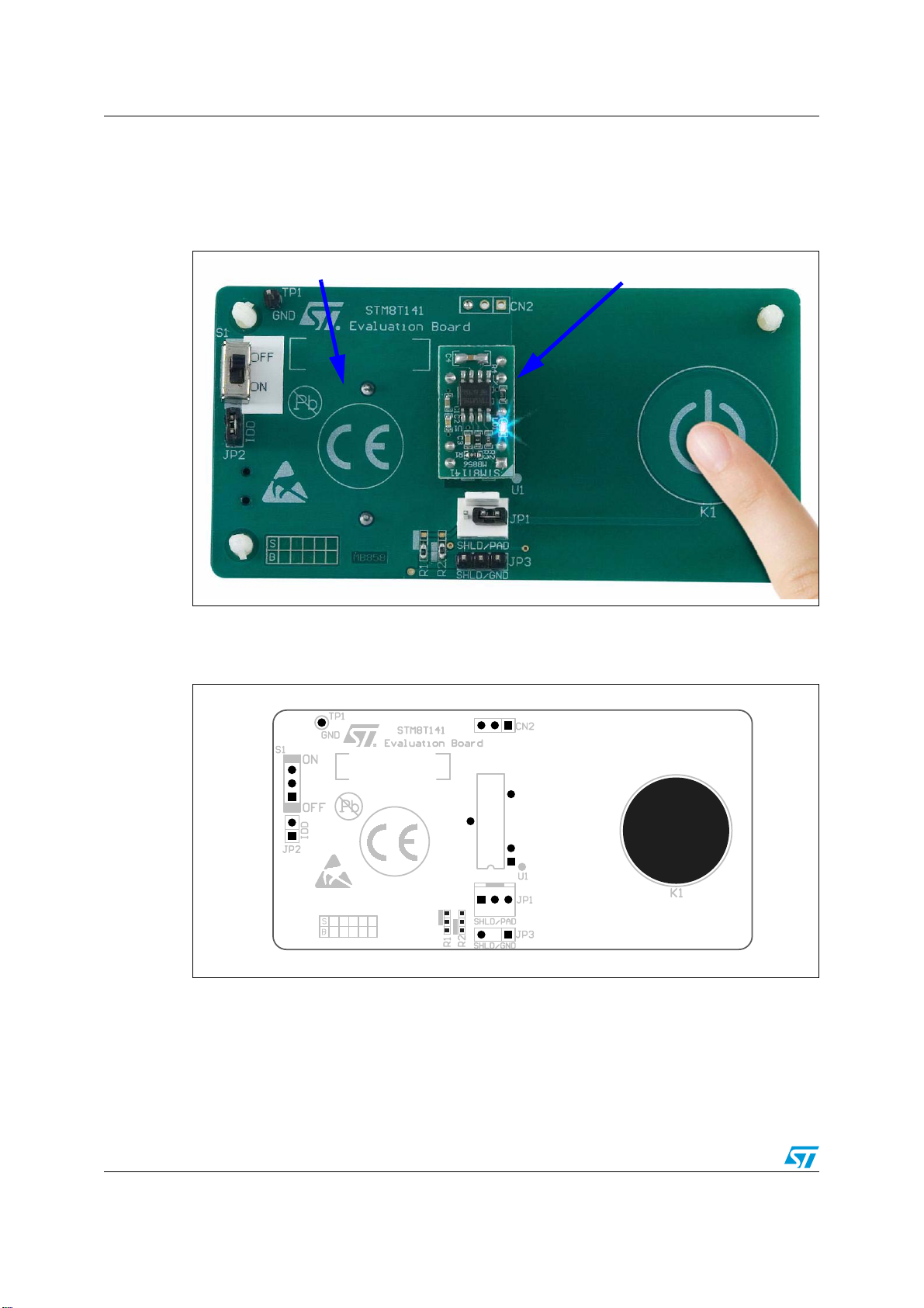
The STM8T141 plug-in module PCB is green.
The STM8T141 touch/proximity output (TOUT/POUT) is connected to an LED which is
turned on when a touch or proximity detection occurs. The LED color depends on the
STM8T141 module configuration (refer to Ta bl e 2 and Figure 7). Refer to Ta ble 4 for the
description of STM8T141 module pins.
Table 2. STM8T141 configuration color coding and marking
PCB color Module configuration PCB marking LED color
Green Proximity detection No marking Blue
Sensitive Touch detection White dot ink marking Red
Table 3. Option bytes
Mode Sensitive touch description Standard proximity description
Power mode Low power mode with zoom Low power mode with zoom
Sensitivity threshold Sensitive touch Standard proximity
Recalibration timeout 15 seconds 15 seconds
TOUT/POUT output mode Active Active
Sampling conversion
period 20 ms 20 ms
Charge transfer frequency 125 kHz 125 kHz