Meccanica Fadini Astro 40 User manual

®
s.n.c .
Via Mantova, 177/A - 37053 Cerea (Verona) Italy -
Tel. 0442 330422 r.a.
aut.
40
Astro
40,665 MHz, ROLLING CODE
Dis. N. 3953
Fig.1 Fig.2
Fig.4
Fig.3
14
15 1°operazione • Step 1
2°operazione • Step 2
3°operazione • Step 3 5°operazione • Step 5
4°operazione • Step 4
SPECIFICA PER LA COMPOSIZIONE DEL CODICE E SUA FUNZIONALITÀ
QUALSIASI PULSANTE DEL TRASMETTITORE PUO’ ESSERE SELEZIONATO PER ENTRARE IN QUALSIASI CANALE CHE NECESSITA; OCCORRE
INSERIRE IL PONTICELLO “STRIP” NELLA POSIZIONE DESIDERATA. COMPORRE IL CODICE COME DA DESCRIZIONE.
Alimentare la scheda radio ricevente ad innesto e da esterno. Inserire orizzontalmente il ponticello “STRIP” nella posizione”C1”, stimolando
così il relè “1R”. La prossima operazione è quella di premere contemporaneamente il pulsante “P” posto sulla scheda radio e un pulsante a
scelta del trasmettitore per 5 secondi (la spia rossa sulla scheda lampeggerà confermandoci l’avvenuta memorizzazione del codice). Lasciamo
in posizione di riposo il tasto del trasmettitore e il pulsante della scheda radio; togliamo il ponticello “STRIP” e lo infiliamo in un solo “PIN”.
Abbiamo ottenuto la codifica del 1°pulsante. Per codificare il 2°canale di uscita, si procede sempre come descritto precedentemente, con
l’accorgimento di inserire orizzontalmente lo “STRIP” nella posizione “C2”, stimolando il secondo relè “2R” con un altro pulsante del trasmettitore.
Il collegamento del morsetto di uscita del 2°canale può essere aperto (N.A.) Oppure chiuso (N.C.). Per ottenere tutte le possibilità di applicazione.
CANCELLARE E RENDERE NULLO IL CODICE (Fig.4): PER CANCELLARE UN CODICE IMPOSTATO SU DI UNA RADIO RICEVENTE, SI DEVONO
SEGUIRE DELLE OPERAZIONI ALTERNATE IN SEQUENZA SULLO STESSO TRASMETTITORE, ESEGUENDOLE AD UNA DISTANZA DI 10 O
20 METRI DALLA RICEVENTE.
Collegare l’antenna alla radio ricevente, quindi inserire il ponticello “Strip” nella posizione “P1”, e alimentare la scheda radio ricevente.
1°Operazione:
Schiacciare
contemporaneamente e poi
Rilasciare
i primi due tasti del trasmettitore.
2°Operazione:
Schiacciare
e poi
Rilasciare
il primo pulsante.
3°Operazione: ...eseguire le prime 2 operazioni per un totale di 5 volte; considerando che si hanno 10 secondi di tempo massimo tra una operazione e l’altra.
NEL CASO SI SBAGLI A CONTEGGIARE IL NUMERO DELLE OPERAZIONI SVOLTE O LA SEQUENZA DEI TASTI DA SCHIACCIARE, BISOGNA RIPARTIRE DALLA 1°OPERAZIONE ASPETTANDO
1 MINUTO PRIMA DI INIZIARE LA PROCEDURA.
NOTA: Per più trasmettitori da cancellare, bisogna eseguire l’intera procedura descritta per ognuno dei singoli trasmettitori.
TRASMETTITORE - RADIO RICEVENTE (conforme alle norme Europee: BT 93/68/CEE - EMC 89/336/CEE - R&TTE 99/05/CE)
aut.
40
Astro - Quarzata 40,665 MHz, ad autoapprendimento, ROLLING-CODE
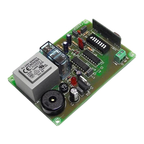
Componenti Fig.1, Fig.2 e Fig.3
1 - Scheda Radio ad Innesto Astro 40
2 - Quarzo
3 - “Strip” ponticello
4 - Connettore ad Innesto
5 - Connettore nel programmatore Elpro
6 - 1°Canale N.A.
7 - Uscita di collegamento del 2°canale
8 - Led di segnalazione
9 - Memoria estraibile
10 - Morsetto antenna
11 - Pulsante “P”
12 - Scheda Radio da Esterno Astro 40
13 - Modulo a relè
14 - Trasmettitore Astro 40/2
15 - Trasmettitore Astro 40/4
SPECIFICATIONS FOR CODE COMPOSITION AND OPERATION
ANY TRANSMITTER BUTTON CAN BE USED TO ENTER ANY CHANNEL REQUIRED; INTRODUCE THE “STRIP” JUMPER INTO THE DESIRED
POSITION AND COMPLETE THE CODE AS DESCRIBED.
Power the plug-in and stand-alone radio receiver card. Horizontally slide the “STRIP” jumper into the “C1” position, thus stimulating the
relay “1R”. Then simultaneously press down the “P” button on the radio card and a transmitter button of your choice for five seconds (the
red pilot light on the card will light up to confirm that the code has been stored). Leave the transmitter key and the radio card button in the
rest position; remove the “STRIP” jumper and thread it into a single “PIN”. This provides the 1st button code. In order to code the 2nd output
channel, repeat the steps described above this time horizontally sliding the “STRIP” into the “C2” position, thus stimulating the second relay
“2R” with another transmitter button. The connection of the output terminal of the 2nd channel can be open (N.O.) or closed (N.C.) in order
to obtain all application possibilities.
ERASING AND INVALIDATING THE CODE (Fig.4): IN ORDER TO CANCEL A CODE SET ON A RADIO RECEIVER, PROCEED FOLLOWING
ALTERNATE OPERATIONS IN SEQUENCE ON THE TRANSMITTER, PERFORMING THEM AT A DISTANCE OF 10 OR 20 METRES FROM THE
RECEIVER
Connect the antenna to the radio receiver, then introduce the “Strip” jumper in position “P1” and power the radio receiver card.
Step one:
Simultaneously press down
and then
Release
the first two transmitter keys.
Step two:
Press down
and then
Release
the first button.
Step three: ...repeat the first two steps five times; remembering that there is a maximum interval of 10 seconds between steps.
IF YOU FORGET THE NUMBER OF STEPS PERFORMED OR MAKE MISTAKES IN THE SEQUENCE OF THE KEYS TO BE PRESSED, RECOMMENCE FROM THE 1ST STEP WAITING 1 MINUTE
BEFORE STARTING THE PROCEDURE.
N.B.: if more than one transmitter is to be erased, perform the entire procedure described above for each one of the single transmitters.
RADIO RECEIVER-TRANSMITTER (conforming to European standards: BT 93/68/EEC - EMC 89/336/EEC - R&TTE 99/05/EC)
aut.
40
Astro - Quartz radio control 40.665 MHz, Self-learning “ROLLING-CODE”
Components Fig.1, Fig.2 and Fig.3
1 - Astro 40 plug-in radio card
2 - Quartz
3 - “Strip” jumper
4 - Plug-in connector
5 - Connector in the Elpro programmer
6 - 1st Channel N.O.
7 - Connection output of the 2nd channel
8 - Pilot light
9 - Removable memory
10 - Antenna terminal
11 - “P” button
12 - Astro 40 stand alone radio card
13 - Relay module
14 - Astro 40/2 transmitter
15 - Astro 40/4 transmitter
1ère opération • 1. Schritt
2ème opération • 2. Schritt
3ème opération • 3. Schritt 5ème opération • 5. Schritt
4ème opération • 4. Schritt
1°operación • 1ehandeling
2°operación • 2ehandeling
3°operación • 3ehandeling 5°operación • 5ehandeling
4°operación • 4ehandeling
1
2
3
4
5
624V
7
8
9
10
11
C1
C2
P1
P2
C1
C4
C3
C2
2
3
8
9
10
11
12
13
24V
1°
2°
3°
4°
P1
P2
I
GB

FONCTIONNALITÉ DU CODE ET SPÉCIFICATION POUR SA COMPOSITION
VOUS POUVEZ SÉLECTIONNER UNE TOUCHE QUELCONQUE DE L’ÉMETTEUR POUR ENTRER DANS N’IMPORTE QUEL CANAL; VOUS DEVEZ
PLACER LE PONT “STRIP” DANS LA POSITION VOULUE. COMPOSEZ LE CODE DE LA FAÇON DÉCRITE.
Alimentez la carte radio récepteur enfichable et modulaire. Placez le pont “STRIP” horizontalement dans la position “C1” ce qui a pour effet
d’exciter le relais “1R”. Appuyez ensuite en même temps sur la touche “P”, placée sur la carte radio, et sur la touche de votre choix, placée
sur l’émetteur, pendant 5 secondes (la led rouge de la carte s’éclaire pour confirmer que le code est mémorisé). Laissez au repos la touche
de l’émetteur et celle de la carte radio; ôtez le pont “STRIP” et enfilez-le dans une seule “BROCHE”. Vous venez de codifier la 1ère touche.
Procédez de la même façon pour codifier le 2ème canal de sortie, en n’oubliant pas de placer horizontalement le “STRIP” dans la position
“C2”, ce qui excite le deuxième relais “2R” avec une autre touche de l’émetteur. Le branchement de la borne de sortie du 2ème canal peut
rester ouvert (N.O.) Ou fermé (N.F.) Pour obtenir toutes les possibilités d’application.
EFFACER ET ANNULER LE CODE (Fig. 4): POUR EFFACER UN CODE SAISI SUR UN RÉCEPTEUR RADIO, VOUS DEVEZ EXÉCUTER
DES OPÉRATIONS QUI SE SUCCÈDENT EN SÉQUENCE SUR L’ÉMETTEUR, À UNE DISTANCE DE 10 À 20 MÈTRES DU RÉCEPTEUR.
Branchez l’antenne sur le récepteur radio, puis placez le pont “Strip” dans la position “P1” et alimentez le récepteur radio.
1ère opération:
Appuyez
en même temps les deux premières touches de l’émetteur puis
lâchez
-les.
2ème opération:
Appuyez
sur la première touche puis
lâchez
-la.
3ème opération: ...exécutez les deux premières opérations 5 fois en tout ; sachant que vous disposez de 10 secondes au maximum entre deux opérations.
SI VOUS VOUS TROMPEZ DANS LE COMPTE DU NOMBRE DES OPÉRATIONS EXÉCUTÉES OU DE LA SÉQUENCE DES TOUCHES À ENFONCER, VOUS DEVEZ RECOMMENCER À PARTIR
DE LA 1ÈRE OPÉRATION EN ATTENDANT 1 MINUTE AVANT DE COMMENCER LA PROCÉDURE.
REMARQUE: Pour effacer plusieurs émetteurs, vous devez exécuter toute la procédure décrite avec chaque émetteur.
ÉMETTEUR – RÉCEPTEUR RADIO (conforme aux normes européennes : BT 93/68/CEE - EMC 89/336/CEE - R&TTE 99/05/CE)
aut.
40
Astro - Au Quartz 40,665 Mhz, et Auto-apprentissage, ROLLING-CODE
Composants Fig. 1, Fig. 2 et Fig. 3
1 - Carte radio enfichable Astro 40
2 - Quartz
3 - Pont “Strip”
4 - Connecteur à enficher
5 - Connecteur dans le programmeur Elpro
6 - 1er canal N.O.
7 - Sortie de connexion du 2ème canal
8 - Led de signalisation
9 - Mémoire enfichable
10 - Borne antenne
11 - Touche “P”
12 - Récepteur radio modulaire Astro 40
13 - Module à relais
14 - Emetteur Astro 40/2
15 - Emetteur Astro 40/4
ANLEITUNG ZUR EINGABE DES CODES UND SEINE FUNKTIONSWEISE
ES KANN JEDE BELIEBIGE TASTE DES HANDSENDERS GEWÄHLT WERDEN, UM IN JEDEN BELIEBIGEN ERFORDERLICHEN KANAL ZU
GELANGEN; ES IST NOTWENDIG DIE “STRIP“ BRÜCKE IN DIE GEWÜNSCHTE POSITION EINZUFÜGEN. DEN CODE ENTSPRECHEND DER
BESCHREIBUNG EINGEBEN.
Das aufsteckbare und das außen anzubringende Funkempfänger-Modul mit Strom versorgen. Die “STRIP” Brücke waagerecht in die Position
”C1” einfügen, wobei auf diese Weise das Relais “1R” anzieht. Der nächste Schritt besteht darin, gleichzeitig 5 Sekunden lang die Taste “P”,
die sich auf dem Empfängermodul befindet und eine beliebige Taste auf dem Handsender zu drücken (das rote LED auf dem Modul wird
blinken, wodurch uns die erfolgte Speicherung des Codes bestätigt wird). Lassen wir die Taste des Handsenders und Knopf des Empfängermoduls
in Ruheposition; entfernen wir die “STRIP” Brücke und stecken wir ihn in nur einen “PIN”. Wir haben die Kodifizierung der 1. Taste erreicht.
Um den 2. Ausgangskanal zu codieren wird genauso wie vorher beschrieben verfahren, wobei darauf geachtet werden muss, dass die “STRIP”
waagerecht in die Position “C2” eingefügt werden muss, wodurch das zweite Relais “2R” durch eine andere Taste des Handsenders angezogen
wird. Der Anschluss an die Ausgangsklemme des 2. Kanals kann entweder offen sein (Normalerweise Offen) oder geschlossen sein (Normalerweise
Geschlossen) um alle Anwendungsmöglichkeiten zu erhalten.
DEN CODE LÖSCHEN ODER ANNULLIEREN (Abb.4): ZUM LÖSCHEN EINES CODES, DER IN EINEM FUNKEMPFÄNGER GESPEICHERT WORDEN
IST, MUß MAN ABWECHSELND NACHEINANDER DEN GLEICHEN HANDSENDER BETÄTIGEN, WOBEI SICH DIESER IN EINER ENTFERNUNG
VON 10 ODER 20 METERN VOM EMPFÄNGER BEFINDEN MUß.
Die Antenne an den Funkempfänger anschließen, danach die “STRIP” Brücke in die Position ”P1” einfügen und das Funkempfänger-Modul an die Stromversorgung anschließen.
1. Schritt: Die ersten zwei Tasten des Handsenders gleichzeitig
drücken
und dann
loslassen
.
2. Schritt: Die erste Taste des Handsenders
drücken
und dann
loslassen
.
3. Schritt: ...die ersten 2 Schritte insgesamt 5 Mal durchführen, wobei berücksichtigt werden muss, dass insgesamt maximal 10 Sekunden Zeit zwischen einem Schritt und dem anderen
zur Verfügung stehen.
SOLLTE MAN SICH BEI DER ANZAHL DER DURCHGEFÜHRTEN SCHRITTE ODER BEI DER ANZAHL DER TASTENDRUCKE VERZÄHLT HABEN, SO MUSS MAN WIEDER VOM 1.SCHRITT
NEU ANFANGEN, WOBEI 1 MINUTE LANG GEWARTET WERDEN MUSS BEVOR MAN MIT DER SCHRITTFOLGE WIEDER NEU BEGINNT.
ANMERKUNG: Sind mehrere Handsender zu löschen, so muss man die gesamte beschriebene Schrittfolge für jeden einzelnen Handsender durchführen.
FUNKHANDSENDER – FUNKEMPFÄNGER (gemäß den Europäischen Normen: BT 93/68/EWG - EMC 89/336/EWG - R&TTE 99/05/EG)
aut.
40
Astro - Quarz 40,665 MHz, selbstlernend, mit ROLLING-CODE
Komponenten Abb.1, Abb. 2 und Abb.3
1 - Funkempfänger-Steck-Modul Astro 40
2 - Quarz
3 - “Strip” Brücke
4 - Steckverbinder
5 - Verbinder für Elpro Steuerung
6 - 1. Kanal normalerweise offen
7 - Ausgang Anschluß 2. Kanal
8 - Signal-LED
9 - Herausziehbarer Speicher
10 - Antennen Klemme
11 - Taste “P”
12 - Funkempfänger-Modul für
Außenanschluß Astro 40
13 - Relais-Modul
14 - Astro 40/2 Handsender
15 - Astro 40/4 Handsender
ESPECIFICACIONES PARA LA COMPOSICIÓN DEL CÓDIGO Y PARA SU FUNCIONALIDAD
CUALQUIER PULSADOR DEL TRANSMISOR PUEDE SELECCIONARSE PARA ENTRAR EN CUALQUIER CANAL QUE SE DESEA; ES NECESARIO INSERTAR
EL PUENTE “STRIP” EN LA POSICIÓN DESEADA. COMPONER EL CÓDIGO COMO SE DESCRIBE.
Alimentar la tarjeta del radio receptor de empalme y de exterior. Introducir de forma horizontal el puente “STRIP” en la posición ”C1”, estimulando de
esta manera el relé “1R”. En la siguiente operación se presiona al mismo tiempo el pulsador “P” colocado en la tarjeta radio y un pulsador a elección
del transmisor durante 5 segundos (el indicador rojo de la tarjeta parpadeará confirmando que se ha memorizado el código). Dejamos en posición de
reposo la tecla del transmisor y el pulsador de la tarjeta radio; sacamos el puente “STRIP” y lo colocamos en un solo “PIN”. Hemos conseguido la
codificación del 1°pulsador. Para codificar el 2°canal de salida, se procede según la descripción anterior, teniendo en cuenta insertar horizontalmente
el “STRIP” en la posición “C2”, estimulando el segundo relé “2R” con otro pulsador del transmisor. La conexión del borne de salida del 2°canal
puede ser abierta (N.A.) o bien cerrada (N.C.). Para conseguir todas las posibilidades de aplicación.
BORRAR Y VOLVER NULO EL CÓDIGO (Fig.4): PARA BORRAR UN CÓDIGO PROGRAMADO EN UN RADIO RECEPTOR, SE DEBEN REALIZAR
OPERACIONES ALTERNADAS EN SECUENCIA EN EL MISMO TRANSMISOR, REALIZÁNDOLAS A UNA DISTANCIA DE 10 O 20 METROS DEL RECEPTOR.
Conectar la antena al radio receptor e insertar el puente “Strip” en la posición “P1” y alimentar la tarjeta del radio receptor.
1°Operación:
Apretar
al mismo tiempo y luego
Soltar
las dos primeras teclas del transmisor.
2°Operación:
Apretar
y luego
Soltar
el primero pulsador.
3°Operación: ... realizar las 2 primeras operaciones un total de 5 veces; considerando que se dispone de 10 segundos como tiempo máximo entre una operación y la siguiente.
SI SE COMETE UN ERROR EN EL CONTEO DEL NÚMERO DE OPERACIONES REALIZADAS O EN LA SECUENCIA DE LAS TECLAS A APRETAR, ES NECESARIO VOLVER A COMENZAR DESDE LA 1°
OPERACIÓN, ESPERANDO 1 MINUTO ANTES DE COMENZAR EL PROCEDIMIENTO.
NOTA: Para borrar más transmisores, es necesario realizar el procedimiento entero que se describe para cada uno de los transmisores.
TRANSMISOR - RADIO RECEPTOR (conforme a las normas Europeas: BT 93/68/CEE - EMC 89/336/CEE - R&TTE 99/05/CE)
aut.
40
Astro - Con cuarzo 40,665 MHz, auto-aprendizaje, ROLLING-CODE
Componentes Fig.1, Fig.2 y Fig.3
1 - Tarjeta Radio de Empalme Astro 40
2 - Cuarzo
3 - “Strip” puente
4 - Conector de Empalme
5 - Conector en el programador Elpro
6 - 1°Canal N.A.
7 - Salida conexión del 2°canal
8 - Led de señalización
9 - Memoria extraíble
10 - Borne antena
11 - Pulsador “P”
12 - Tarjeta Radio de Exterior Astro 40
13 - Modulo a relé
14 - Transmisor Astro 40/2
15 - Transmisor Astro 40/4
SPECIFICATIE VOOR DE SAMENSTELLING VAN DE CODE EN HAAR WERKING
ELKE WILLEKEURIGE DRUKKNOP VAN DE ZENDER KAN GEKOZEN WORDEN OM ELK WILLEKEURIG KANAAL TE BETREDEN; DE “STRIP” JUMPER
MOET IN DE GEWENSTE POSITIE WORDEN AANGEBRACHT. VOER DE CODE OVEREENKOMSTIG DE BESCHRIJVING IN.
Voed de radio-ontvangerkaart met de insteek en extern. Breng de “STRIP” jumper horizontaal in de stand “C1” aan, zodat het relais “1R” wordt
gestimuleerd. De volgende handeling is het gelijktijdig bedienen van de drukknop “P” op de radiokaart en een willekeurige drukknop van de zender
gedurende 5 seconden (het rode controlelampje op de kaart zal gaan knipperen, ter bevestiging van de opslag van de code). Laat nu de toets van de
zender en de drukknop van de radiokaart in de ruststand; verwijder de “STRIP” jumper en breng hem in één enkele “PIN” aan. Zo wordt de codering
van de eerste drukknop verkregen. Om het tweede uitgangskanaal te coderen, gaat men te werk zoals hierboven beschreven, door de “STRIP” horizontaal
in positie “C2” aan te brengen, zodat het tweede relais “2R” met een andere drukknop van de zender wordt gestimuleerd. De verbinding van de
uitgangsklem van het tweede kanaal kan open (NO) of gesloten (NC) zijn om alle toepassingsmogelijkheden te verkrijgen.
CODE WISSEN EN ONGELDIG MAKEN (Fig.4): OM EEN IN EEN RADIO-ONTVANGER INGESTELDE CODE TE WISSEN, MOETEN IN SEQUENTIE
AFWISSELENDE HANDELINGEN OP DE ZENDER WORDEN UITGEVOERD OP EEN AFSTAND VAN 10 OF 20 METER VAN DE ONTVANGER.
Sluit de antenne op de radio-ontvanger aan, breng de “Strip” jumper in de positie “P1” aan en voed de radio-ontvangerkaart.
1ehandeling:
druk
de eerste twee toetsen van de zender gelijktijdig in en
laat
ze weer
los
.
2ehandeling:
druk
de eerste drukknop in en
laat
hem weer
los
.
3ehandeling: voer de eerste 2 handelingen 5 keer uit; houd er rekening mee dat er maximaal slechts 10 seconden tussen de ene en de andere handeling mogen verlopen.
INDIEN MEN ZICH BIJ DE SEQUENTIE VAN DE UITGEVOERDE HANDELINGEN OF BIJ HET INDRUKKEN VAN DE TOETSEN VERGIST, MOET MEN OPNIEUW MET DE PROCEDURE VANAF DE EERSTE
HANDELING BEGINNEN NA MINSTENS 1 MINUUT GEWACHT TE HEBBEN.
Opmerking: Als meerdere zenders gewist moeten worden, moet de volledige hierboven beschreven procedure voor elke afzonderlijke zender worden uitgevoerd.
RADIO-ONTVANGER / -ZENDER (conform de Europese normen: BT 93/68/CEE - EMC 89/336/CEE - R&TTE 99/05/CE)
aut.
40
Astro - Kwarts 40,665 MHz, met self-learning, ROLLING-CODE
Componenten Fig.1, Fig.2 e Fig.3
1 - Insteekradiokaart Astro 40
2 - Kwarts
3 - “Strip” jumper
4 - Insteekconnector
5 - Connector in de Elpro programmer
6 - 1ekanaal NO
7 - Verbindingsuitgang van het tweede kanaal
8 - Signaleringsled
9 - Uitneembaar geheugen
10 - Antenneklem
11 - Drukknop “P”
12 - Externe radiokaart Astro 40
13 - Relaismodule
14 - Zender Astro 40/2
15 - Zender Astro 40/4
NL
E
D
F
Other Meccanica Fadini Receiver manuals


